- sales/support
Google Chat: zj734465502@gmail.com
- sales
+86-0755-88291180
- sales01
sales@spotpear.com
- sales02
dragon_manager@163.com
- support
tech-support@spotpear.com
- CEO-Complaints
zhoujie@spotpear.com
- sales/support
WhatsApp:13246739196
15.6HP-CAPQLED User Guide
Overview
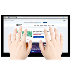
This product is a universal 15.6-inch HDMI QLED quantum dot display with a resolution of 1920 × 1080 and an optical bonding toughened glass capacitive touch panel. Raspberry Pi is supported and can also be used as a computer monitor.
Feature
- The 15.6-inch QLED quantum dot display has the advantages of a high color gamut, pure chromaticity, and long service life.
- The hardware resolution is 1920 × 1080.
- 10-point capacitive touch control, optical bonding process, better display effect, toughened glass touch panel, hardness up to 6H.
- When used with Raspberry Pi, supports Raspberry Pi OS / Ubuntu / Kali and Retropie.
- Ubuntu is supported when used with Jetson Nano.
- When used as a computer monitor, supports Windows 11/10/8.1/8/7.
- Support mainstream game consoles, such as Microsoft Xbox360, Sony PS4, Nintendo SWITCH, etc.
- Support multi-language OSD menu (can be used for power control, adjusting brightness/contrast, etc.).
- With 3.5mm audio jack, 4PIN speaker port, support HDMI audio output.
Onboard Resource
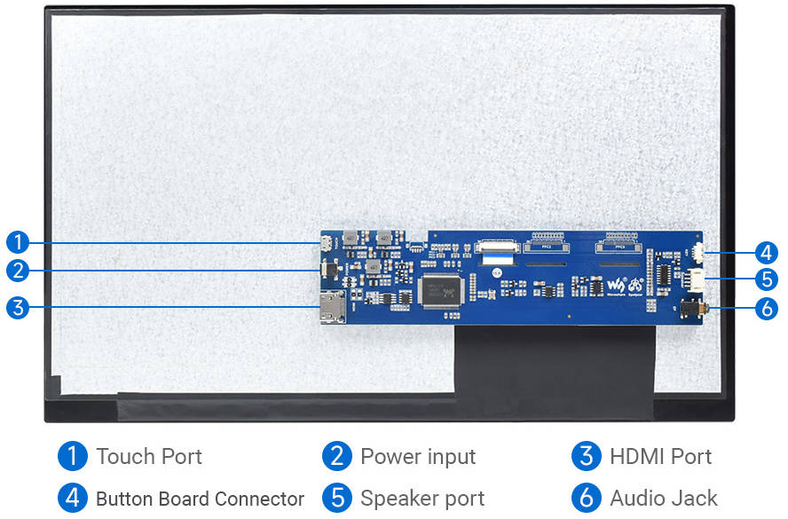
Working with Raspberry Pi
Support Raspberry Pi OS/Ubuntu/Kali and Retropie system.
1. Please download the latest version of the image from Raspberry Pi official website.
2. Download the compressed file to the PC and extract it to get the .img file.
3. Connect the TF card to the PC, and use the SDFormatter software to format the TF card.
4. Open the Win32DiskImager software, select the system image prepared in step 1, and click "write" to program the system image.
5. After the programming is completed, open the config.txt file in the root directory of the TF card. Please add the following code at the end of config.txt, save and safely eject the TF card, and then insert the TF card into the Raspberry Pi.
hdmi_group=2
hdmi_mode=82
hdmi_cvt 1920 1080 60 6 0 0 0
6. Connect the 12V power supply to the DC interface of the LCD, and you can see that the LCD backlight is lit normally.
7. Connect the Touch port of the LCD to the USB port of the Raspberry Pi, and the HDMI port of the LCD to the HDMI port of the Raspberry Pi.
8. Power on the Raspberry Pi and wait for a few seconds to display normally.
Working with Horizon Sunrise X3 Pi
Support Ubuntu20.04 system.
Please download the ubuntu20.04 image from here, and then program the system according to the user manual.
- How to use:
- 1) Connect the 12V power supply to the DC port of the LCD, and you can see the LCD backlight is on.
- 2) Connect the HDMI interface of the X3 Pi to the touch interface of the LCD.
- 3) Connect the HDMI interface of the X3 Pi to the HDMI interface of the LCD.
- 4) Connect the 5V power supply to the X3 Pi and power on it.
Note:
- If you connect the LCD after booting X3 Pi, and there is no image on the LCD, you need to reboot the X3 Pi.
Working with PC
This product supports Windows 11/10/8.1/8/7 system.
How to use:
Step 1: Connect the 12V power supply to the DC interface of the LCD, and you can see that the LCD backlight is on normally.
Step 2: Connect the TOUCH interface of the LCD to the USB port of the PC. Windows will automatically recognize the touching function after a while.
Step 3: If you want to use HDMI communication, you can connect the HDMI of the LCD to the HDMI of the PC. You can see that LCD can display normally after 3 seconds. If you need to output sound, you can output HDMI audio through the 3.5mm headphone jack or 4PIN speaker.
Notice:
1) When the PC is connected to multiple monitors at the same time, the touch effect works on the main screen by default. If you need to specify the touch to the secondary screen, see #Calibration touch on Win 10 PC.
2) Some PCs do not support plug-and-play with HDMI devices. Generally, they can be used normally after restarting the system.
3) HDMI audio output can be used normally only during HDMI communication.
Calibration touch on Win 10 PC
Take the windows10 system as an example:
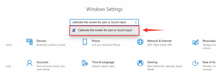
- 1. Enter the Windows settings of the system, type in the search bar and click "Calibrate the screen for pen or touch input" (as shown in the picture below).
- 2. Click "Setup" in the pop-up "Tablet PC Settings" interface:
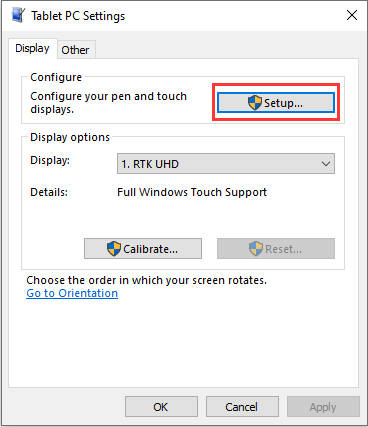
- 3. The following text prompt will appear on the screen. Please tap the touch screen with your finger, and the computer will recognize it as a touch screen.
【Note】If the touch screen is blank, press the "Enter" key, and the text prompt will switch to the touch screen. (The screen which displays the text prompt will be used as a touch screen!)

How to Install the Display
Double-sided tape is used between the LCD of the screen and the touchpad. It is necessary to consider supporting the LCD, and a reference example is given below.
NOTE: The assembly materials used below are not included in the shipped kit! ! This is only for reference.
Reference Schematic
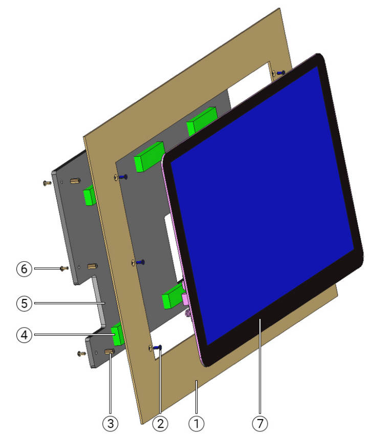
Part Name:
1. Case
2. Countersunk head screw
3. Copper pillars
4. Adhesive sponge
5. Acrylic sheet (thickness 5mm and above)
6. Round head screw
7. HDMI LCD
Assembly Instructions:
1. Fix the copper pillar ③ on the back of the device case ① with the countersunk head screw ②, and then insert the HDMI LCD ⑦ into the device case ① and bond it firmly. The countersunk head screw holes on the casing will be blocked by the edge of the screen. No screws are visible on the surface.
2. Paste the adhesive sponge ④ with a suitable thickness on the acrylic board ⑤, pay attention to the position of the sticker to avoid the PCB board, and finally fix it on the copper pillar ③ with the round head screw ⑥. After assembly, please make sure that the sponge is completely attached to the back of the LCD.
3. Holes need to be made in the acrylic sheet to avoid the components on the PCB board, which can facilitate the connection between the interface and the device.
Note: The LCD display surface cannot be installed parallel to the ground, otherwise it will fall off under gravity. In addition, when it needs to be installed at an angle, the back of the LCD screen should keep an angle of fewer than 75 degrees with the horizontal direction.
Resource
Software
3D Drawing
FAQ
Add the following command to /boot/config.txt:
disable_splash=1Replace the custom image with the image in this directory /usr/share/plymouth/themes/pix/splash.png.
Test environment: 2022-04-04-raspios-bullseye-armhf 32-bit system
Supported models: Support Waveshare DSI LCD, DPI LCD, and HDMI LCD capacitive touch screen series.64bit system does not support by default
Software Installation
wget https://files.waveshare.com/upload/1/18/Evdev-right-click-emulation.zip
unzip Evdev-right-click-emulation.zip
cd evdev-right-click-emulation
sudo apt install build-essential libevdev2 libevdev-dev
cd 'evdev-right-click-emulation'
sudo cp 'out/evdev-rce' '/usr/local/bin/'
sudo chmod +x '/usr/local/bin/evdev-rce'
Enter the command:
sudo evdev-rce
After running, you can touch and long press to realize the right-click function.
Set IP
sudo usermod -G 'input' -a pi
echo 'uinput' | sudo tee -a /etc/modules
sudo nano  /etc/udev/rules.d/99-uinput.rules
Add in 99-uinput.rules file.
KERNEL=="uinput", MODE="0660", GROUP="input"
save it and run it in the terminal.
sudo udevadm control --reload-rules
sudo udevadm trigger
Then reboot:
sudo reboot
Run after reboot (no sudo needed at this point).
evdev-rce
After running, you can touch and long press to realize the right-click function.
Set Startup
Enter the terminal:
sudo mkdir ~/.config/autostart
sudo nano ~/.config/autostart/right_click.desktop
Add the following in right_click.desktop.
[Desktop Entry]
Version=1.0
Type=Application
Name=evdev-rce
GenericName=Enable long-press-to-right-click gesture
Exec=env LONG_CLICK_INTERVAL=1000 LONG_CLICK_FUZZ=200  /usr/local/bin/evdev-rce
Terminal=true
StartupNotify=false

#If you want to modify the sensitivity, you can modify the size of the two parameters, LONG_CLICK_INTERVAL=1000 LONG_CLICK_FUZZ=200.
350cd/㎡
60Hz.
It depends on the system. If the system has a sleep mode, the screen will also go black. If it's the official Raspberry Pi system, it typically goes into sleep mode after about ten minutes of inactivity.
Remove the triode shown in the figure below, and solder the PWM pin on the pad indicated by the arrow on the right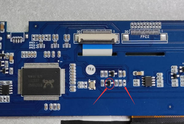
Execute the following command on the Raspberry Pi terminal:
 gpio -g pwm 18 0
 gpio -g mode 18 pwm (occupied pins are PWM pins)
 gpio pwmc 1000
 gpio -g pwm 18 X (X ranges from 0 to 1024), 0 is the brightest, 1024 is the darkest
Support up to 2.6W, 2x speakers, and each speaker supports up to 1.3W.
12V 1A outer diameter 3.5 and inner diameter 1.35. If you want to use other power supplies, you need to ensure that the power supply ripple is within ±5%.
Support
Monday-Friday (9:30-6:30) Saturday (9:30-5:30)
Mobile: +86 13434470212
Email: services01@spotpear.com
[Tutorial Navigation]
- Overview
- Feature
- Onboard Resource
- Working with Raspberry Pi
- Working with Horizon Sunrise X3 Pi
- Working with PC
- How to Install the Display
- Resource
- FAQ
- Question:How to remove the colored squares during GPU self-test on Raspberry Pi boot-up?
- Question:How to replace the Raspberry Pi startup logo image?
- Question:How to set long press touch on Raspberry Pi capacitive touch screen?
- Software Installation
- Set IP
- Set Startup
- Question:What is the pure white brightness of this screen?
- Question:What is the refreshing rate of this screen?
- Question:Does this screen automatically turn off, or do you need to execute a command to turn it off?
- Question:How to use PWM to control the backlight of 15.6HP-CAPQLED?
- Question:What speaker is compatible with the 4PIN header of 15.6HP-CAPQLED?
- Question:What is the power supply for this screen?
- Support


