- sales/support
Google Chat:---
- sales
+86-0755-88291180
- sales01
sales@spotpear.com
- sales02
dragon_manager@163.com
- support
tech-support@spotpear.com
- CEO-Complaints
zhoujie@spotpear.com
- Only Tech-Support
WhatsApp:13246739196
- Purchase/Shipping/Refund
WhatsApp:13424403025
- HOME
- >
- ARTICLES
- >
- Common Moudle
- >
- UART Module
SX1262-LoRa-DTU-LF / HF User Guide
Overview
This product does not support LoRaWAN.
This product does not support communication with other LoRa products.
At least 2x SX1262-LoRa-DTU-HF are required to form a LoRa communication network (SX1262-LoRa-DTU-LF is the same).
Introduction
SX1262-LoRa-DTU is a wireless data transfer unit with RS232, RS485, and RS422 interfaces based on the SX1262 module. Adopts LoRa Modulate and Demodulate technology, with the advantages of anti-interference and long-distance communication (up to 5KM). Supports point-to-point, point-to-multipoint, relay network, AES, etc. As it is compact and easy to install, SX1262-LoRa-DTU-xF is suitable for wireless data transmission and device control of industry standard or non-standard user protocol.
Feature
- Adopts LoRa Modulate and Demodulate technology, anti-interference, and long-distance communication
- Adopts the original SX1262 chip, with -148dBm reception sensitivity and 22dBm emit power
- Supports preamble detection, with CRC, automatic packetization, 960 bytes cache functions
- Supports LBT sending, RSSI output, AT command configuration
- AES communication to ensure data transmission security
- Supports multi-level relay networking to increase the wireless communication distance
- Supports host configuration and firmware upgrade (support firmware customization for batch order)
- Adopts high-quality components such as TCXO to ensure stable operation under harsh working conditions
- Comes with online development resources and manual
Parameters
| Communication Interface | |
| Interface | Screw terminals: RS485 × 1, RS422 × 1 DB9 male connector: RS232 × 1 SMA-KE female connector: 6dBi omni-directional antenna × 1 |
| RS485 | Anti-surge, overcurrent protection (reserved 120R balanced resistor header) |
| RS232 | TVS diode, anti-surge, and ESD protection |
| RS422 | Anti-surge, overcurrent protection (reserved 120R balanced resistor header) |
| Wireless Parameters | |
| Frequency Band | Sub-GHz (410~510MHz, 850~930MHz) |
| Signal Modulation | LoRa |
| Encryption | AES |
| Emit Power | +22dBm Max |
| Reception Sensitivity | -148dBm |
| UART Parameters | |
| Baud Rate | 1200 ~ 115200bps |
| Parity Bit | None, Odd, Even |
| Data bit | 8 ~ 9 bits |
| Flow Control | N/F |
| Environmental Requirements | |
| Operating Temperature | 0 ~ 85℃ |
| Humidity Range | 5% ~ 95% relative humidity |
| Others | |
| Power Supply | Screw terminals 6 ~ 28V or DC 12V, overcurrent, overvoltage and reverse-proof |
| Case | Aluminum alloy |
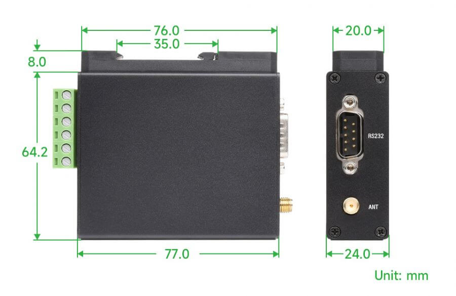
| Dimensions | 77.0 × 24.0 × 64.2mm |
Hardware Description
The SMA interface of SX1262-LoRa-DTU-xF (DTU for short) antenna should face upward, and LED faces outward. The 35mm DIN buckle on the back is embedded into the buckle to fix it, install the antenna to the RS485/RS232/RS422 port and finally connect to the DC12V power supply or terminal power supply (just connect to one kind of power supply).
Note: RS232, RS485, and RS422 cannot be converted to LoRa at the same time, and RS232, RS485, RS422 of the same LoRa cannot be converted to each other.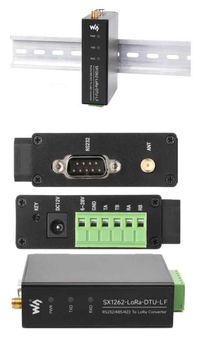
RS485
TA, TB at the bottom of DTU are RS485 half-duplex bus interfaces.
RS232
The DB9 male plug on the top of DTU is RS232 full-duplex bus interface.
RS422
DTU bottom TA, TB, RA, RB are RS422 full-duplex bus interfaces.
Note: RS485 bus interface multiplexes the sending end of RS422.
SMA Port (Antenna)
The SMA interface on the top of the DTU is a supporting 6dBi omnidirectional antenna interface.
Power Port
- DC12V power supply: Use the matching AC-DC power supply to connect the DTU.
- Terminal 6~28V power supply: 6-28V at the 6-pin green terminal, GND is the DC power supply port.
Indicator
- PWR: When connected to DC12V or terminal power supply, the PWR indicator is always on.
- TXD: When sending data, the TXD indicator is on, and it goes out after sending.
- RXD: When receiving data, the RXD indicator is on, and it goes out after receiving.
Key
- KEY: Note: Do not press the button within 3 seconds after powering on.
Dimensions
LoRa & LoRaWAN
What is LoRa ?
[Semtech]'s LoRa is a long-distance, low-power wireless platform for the Internet of Things (IoT), which generally refers to radio frequency chips using LoRa technology. The main features are as follows:
- The spread spectrum modulation technology adopted by LoRa (abbreviation of long-range) is derived from Chirp Spread Spectrum (CSS) technology, which is one of the long-distance wireless transmission technology and LPWAN communication technology. Spread spectrum technology uses bandwidth for sensitivity technology, Wi-Fi, ZigBee, etc. all use spread spectrum technology, but the characteristic of LoRa modulation is that it is close to the limit of Shannon's theorem, and the sensitivity can be improved with maximum efficiency. Compared with traditional FSK technology, at the same communication rate, LoRa is more sensitive than FSK by 8 ~12dBm. At present, LoRa mainly operates in the ISM frequency band of Sub-GHz.
- LoRa technology integrates technologies such as digital spread spectrum, digital signal processing, and forward error correction coding, which greatly improves the performance of long-distance communication. Lora's link budget is better than any other standardized communication technology. The main factors that determine the distance in a given environment.
- LoRa RF chips mainly include SX127X series, SX126X series, SX130X series, of which SX127X, SX126X series are used for LoRa nodes, and SX130X is used for LoRa gateways. For details, please refer to [Semtech]'s product list.
What is LoRaWAN ?
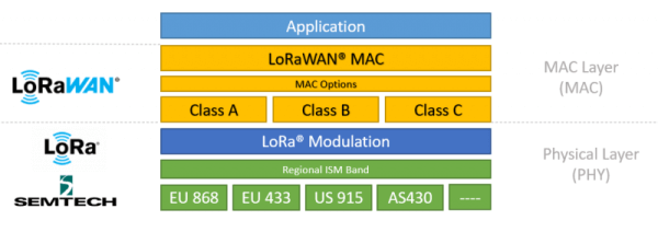
- LoWAN is an open protocol for low-power wide-area networks based on LoRa radio modulation technology. Designed to wirelessly connect battery-powered "things" to the Internet in regional, national, or global networks, and target critical Internet of Things (IoT) requirements such as two-way directional communication, end-to-end security, mobility, and localized services. The node wirelessly connects to the Internet with network access authentication, which is equivalent to establishing an encrypted communication channel between the node and the server. The LoRaWAN protocol level is shown in the figure below.
- The Class A/B/C node devices in the MAC layer basically cover all the application scenarios of the Internet of Things. The differences among the three nodes lie in the different time slots for receiving and receiving nodes.
- EU868 and AS430 in the Modulation layer show that frequency band parameters are different in different countries. Please click the reference [link] for regional parameters.
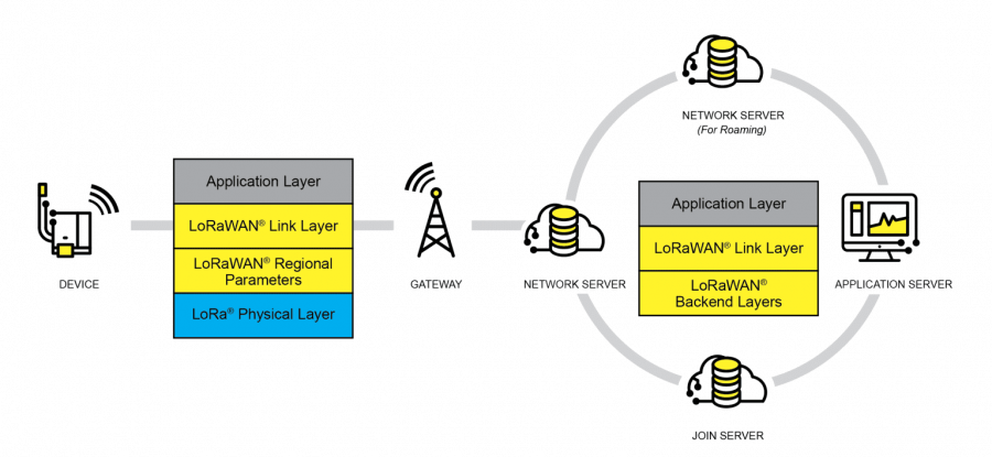
- To achieve LoRaWAN network coverage in cities or other areas, it needs to be composed of four parts: nodes (LoRa node RF chips), gateways (or base stations, LoRa gateway RF chips), Servers, and clouds, as shown in the figure below:
- DEVICE (node device) needs to initiate a network access request packet to GATEWAY (gateway) and then to the server. After passing the authentication, it can normally send and receive application data from the server.
- GATEWAY (gateway) can communicate with the server via a wired network or 3/4/5G wireless network.
- The main operators on the server side include TTN, etc. For building cloud services by yourself, please refer to lorawan-stack, chirpstack.
Application
LoRa devices and networks such as LoRaWAN enable smart IoT applications to help solve the planet's formidable challenges in energy management, natural resource reduction, pollution control, infrastructure efficiency, disaster prevention, and more. Semtech's LoRa devices have achieved hundreds of successful use cases in smart cities, homes and buildings, communities, metrology, supply chain, and logistics, agriculture, and more. LoRa networks have covered hundreds of millions of devices in more than 100 countries and are committed to a smarter planet.
How To Use
Boot Test
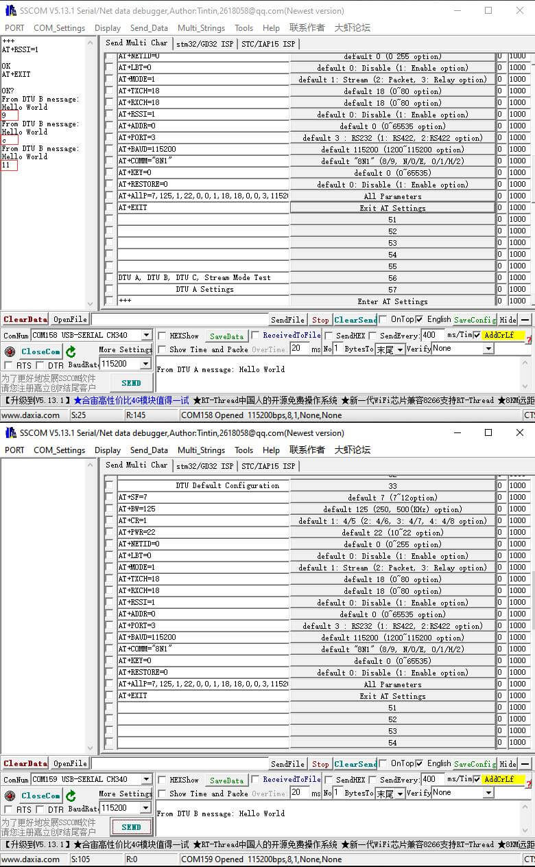
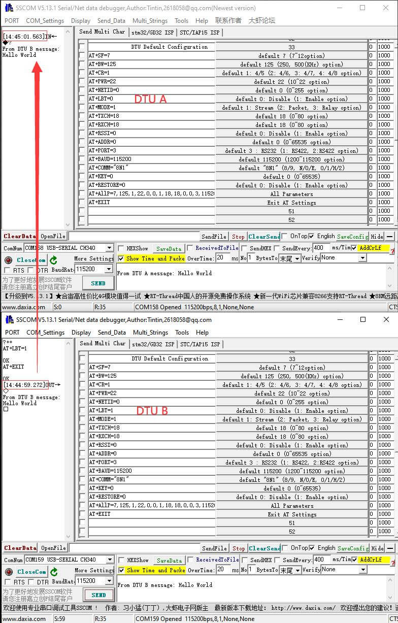
- This test uses two sets of USB to RS232 cables and a DTU connection to test on PC Windows 10, DTU uses an RS232 interface for streaming mode transmission by default when powered on.
- Install DTU's antenna, RS485/RS232/RS422 interface circuit according to the #Hardware Description chapter (power on with RS232 by default, switch to other interfaces to refer to the AT command set), power supply, etc.
- Download and open the AT setting tool or other serial port assistant tools, connect the USB to the RS232 serial port number, set the baud rate to 115200, and finally click to open the serial port.
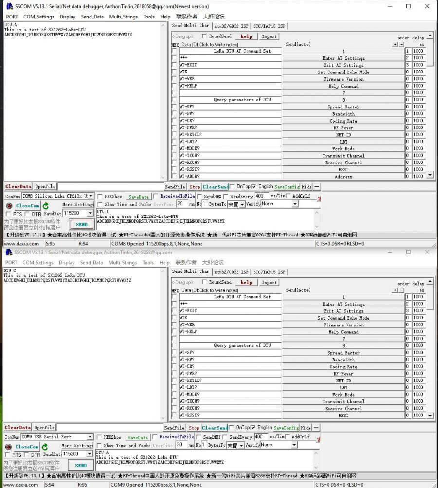
- After entering the data in the SSCOM sending area and clicking the send button, the received data will be printed on the other set of DTU, and vice versa, as shown in the figure below.
- Similarly, other acquisition devices such as PLC can also use DTU to send and receive data.
AT Commands
- The DTU works in the stream transmission mode of the RS232 interface by default, and the default parameters can be used for pairing and sending. The default parameters are as follows
| Parameter | Default Value |
| Spreading Factor | Default 7, (7~12 optional) |
| Bandwidth | Default 0: 125KHz (1:250, 2:500 (KHz) optional) |
| Coding rate | Default 4/5 (4/5, 4/6, 4/7, 4/8 optional) |
| Transmission power | Default 22dBm (10~22dBm optional) |
| Network ID | Default 0 (0~255 optional) |
| LBT (Listen Before Talk) | Default 0: disabled, 1: enabled |
| Working mode | Default 1: stream mode (2: packet mode, 3: relay mode) |
| Transmission channel | Default 18 ( 0~80 is optional, corresponding to 850~930Mhz or 410~490MHz ) |
| Receiving channel | Default 18 ( 0~80 is optional, corresponding to 850~930Mhz or 410~490MHz ) |
| Address | Default 0 (0~65535 optional, 65535 is broadcast listening address) |
| Interface selection | Default 3: RS232 (1: RS422, 2: RS485, 3: RS232 optional) |
| Interface baud rate | Default 115200bps (1200~115200bps optional) |
| Interface parity | No parity by default (none, odd, even parity) |
| Key | Default 0 no encryption (0~65535 optional) |
- For DTU settings, please check the add CRLF or add the carriage return line feed option. If the extension bar does not appear, click the extension button on the right to pop up. Click the +++ command button to enter the AT command mode, as shown in the figure below:
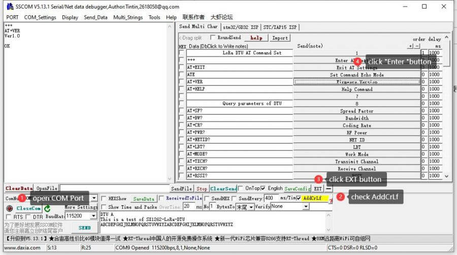
- When configuring DTU for other devices such as PLC, pay attention to the carriage return and line feed character CR LF(\r\n) at the end of the AT command.
+++\r\n                                               Enter AT command mode
AT+EXIT\r\n                                           Exit AT command mode
ATE\r\n                                               Enable/disable AT command echo
AT+VER\r\n                                            Check the software version number
AT+HELP\r\n                                           View AT help

AT+SF=7\r\n                                           Set the spreading factor to 7, the value range is 7~12
AT+BW=0\r\n                                           Set bandwidth, 0 means 125KHz, 1 means 250KHz, 2 means 500KHz
AT+CR=1\r\n                                           Set the encoding rate to 1, 1 represents 4/5, 2 represents 4/6, 3 represents 4/7, 4 represents 4/8
AT+PWR=22\r\n                                         Set the RF power, the value range is 10~22dBm.
AT+NETID=0\r\n                                        Network ID assignment, the value range is 0~65535
AT+LBT=0\r\n                                          Enable/disable LBT function, 0: disable, 1: enable
AT+MODE=1                                             DTU working mode, 1: stream mode, 2: packet mode, 3: relay mode
AT+TXCH=18\r\n                                        Transmit channel, value range 0~80, corresponding frequency point is 850~930MHz or 410~490MHz
AT+RXCH=18\r\n                                        Receive channel, value range 0~80, corresponding frequency point is 850~930MHz or 410~490MHz
AT+RSSI=0\r\n                                          Enable/disable RSSI signal value output, 0: disable, 1: enable
AT+ADDR=0\r\n                                          Set DTU address, value range 0~65535
AT+PORT=3\r\n                                          Set COM port, 1:RS422, 2:RS485, 3:RS232
AT+BAUD=115200\r\n                                     Set COMx port baud rate, value range 1200~115200 , 1200, 2400, ..... , 57600 ,115200ss
AT+COMM="8N1"\r\n                                      Set COM port parameters, data bits: 8 or 9, parity: N, O, E, stop bits: 0, 1, 2
AT+KEY=0\r\n                                           Set the key, the value range is 0~65535, 0: prohibit encryption, 1~65535: encrypt the transmission key value
AT+AllP=7,125,1,22,0,0,1,18,18,0,0,3,115200,"8N1",0    Set the spreading factor to key multi-parameter
AT+RESTORE=0\r\n                                       Restore factory settings, 0: disabled, 1: enabled
Stream Transfer Mode
- DTU is in the stream mode when working in the RS232 interface by default, and the factory default parameters can be used for pairing and sending.
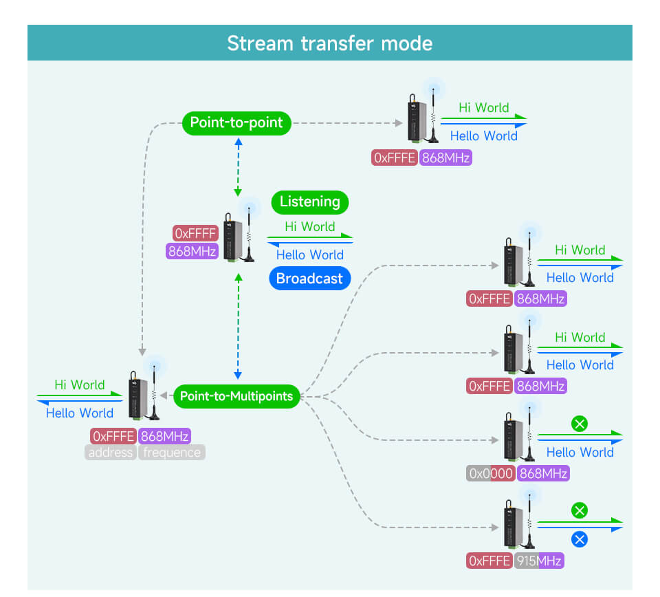
- Streaming mode refers to a transmission mode in which the DTU transmits the data stream sent by the interface to other DTUs for demodulation by LoRa and outputs the data stream from the specified interface, that is, send and receive as shown below:
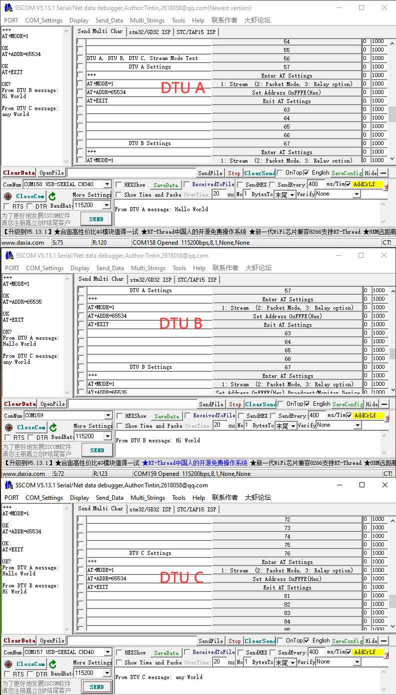
- Suppose there are DTU A, B, C, D, E, F, and G devices to form a stream mode communication network. To change the address, channel, and working mode of the DTU device in the LoRa network, please refer to the following communication diagram and parameter table, pay attention to using the AT command (AT+MODE=1\r\n) to switch to the streaming mode.
- DTU A and DTU C form point-to-point communication.
- DTU A sends Hello World to the DTU C device, DTU C device with a matching address channel can receive it normally.
- DTU C sends Hello World to the DTU A device, DTU A device with a matching address channel can receive it normally.
- DTU A, B, C, D, E, and F constitute stream mode point-to-multiple communication, DTU B address is set to 65535 (Hex: 0xFFFF), at this time it will be used as a device with broadcast monitoring function in the LoRa network, DTU B broadcast when sending data streams, devices with addresses 0~65535 in the same channel can receive data streams, and when other devices send data streams, DTU B can monitor the data streams of devices with addresses 0~65535 in the same channel.
- DTU B broadcasts and sends HI World data streams, DTU A, C, D, and E devices with matching channels receive normally, and DTU F devices with mismatched channels fail to receive.
- When DTU A, C, D, and E send data stream, such as DTU A sends Hello World, DTU B device can monitor the received data stream.
- When a DTU F device with a mismatched channel sends a data stream, DTU B fails to monitor and receive.
- DTU A and DTU C form point-to-point communication.
- Suppose there are DTU A, B, C, D, E, F, and G devices to form a stream mode communication network. To change the address, channel, and working mode of the DTU device in the LoRa network, please refer to the following communication diagram and parameter table, pay attention to using the AT command (AT+MODE=1\r\n) to switch to the streaming mode.
| Parameters | DTU A | DTU B | DTU C | DTU D | DTU E | DTU F |
| Spreading Factor | 7 | 7 | 7 | 7 | 7 | 7 |
| Bandwidth | 0: 125KHz | 0: 125KHz | 0: 125KHz | 0: 125KHz | 0: 125KHz | 0: 125KHz |
| Code rate | 1: 4/5 | 1: 4/5 | 1: 4/5 | 1: 4/5 | 1: 4/5 | 1: 4/5 |
| Operating Mode | 1: Stream mode | 1: Stream mode | 1: Stream mode | 1: Stream mode | 1: Stream mode | 1: Stream mode |
| Address | 65534 (Hex:0xFFFE) | 65535 (Hex:0xFFFF) | 65534 (Hex:0xFFFE) | 65534 (Hex:0xFFFE) | 0 (Hex:0x0000) | 65534 (Hex:0xFFFE) |
| Channel | 18 (Hex:0x12) | 18 (Hex:0x12) | 18 (Hex:0x12) | 18 (Hex:0x12) | 18 (Hex:0x12) | 65 (Hex:0x41) |
| Example 1 | Send Hello World | √ | √ | √ | × | × |
| Example 2 | √ | Send Hi World | √ | √ | √ | × |
| Example 3 | √ | √ | Send any World | √ | × | × |
Packet Transfer Mode
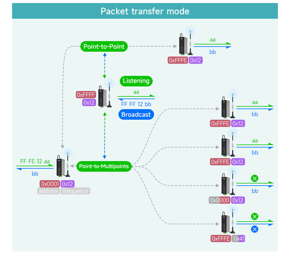
- Packet mode refers to a transmission mode in which DTU communicates with other DTU devices with a specified address and channel. The address and channel of the receiving DTU device are specified in the first 3 bytes of the data stream. The data stream uses a hexadecimal data format.
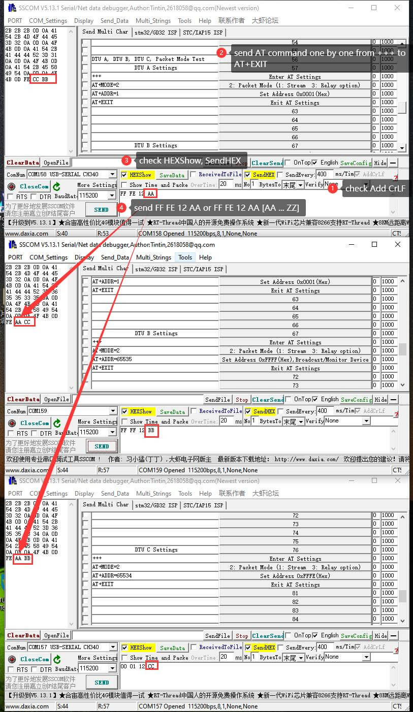
- Suppose there are DTU A, B, C, D, E, and F a total of 6 DTU devices to form a packet mode LoRa communication network, change the address, channel, and working mode of the DTU device in the LoRa network, please refer to the following communication diagram and parameter table, pay attention to use AT command (AT+MODE=2\r\n) to switch to packet mode.
- DTU A and DTU C devices form point-to-point communication in packet mode.
- DTU A sends the hexadecimal data stream FF FE 12 AA, where FF FE is the address of the DTU device (DTU C) receiving the data stream, 12 is the channel of the DTU device (DTU C) receiving the data stream, and AA is the data (Note that the hexadecimal data format is A...Z, such as AA, AZ, ZA, etc.), and the DTU C device whose address channel matches normally receives.
- DTU C sends the hexadecimal data stream 00 01 12 CC, where 00 01 is the address of the DTU device (DTU A) receiving the data stream, 12 is the channel of the DTU device (DTU A) receiving the data stream, and CC is the data (Note that the hexadecimal data format is A...Z, such as AA, AZ, ZA, etc.), and the DTU A device whose address channel matches normally receives.
- DTU A, B, C, D, E, F form the point-to-multiple communication of the packet mode, DTU B address is set to 65535 (Hex: 0xFFFF), at this time it will be used as a device with broadcast monitoring function in the LoRa network, and DTU B will broadcast and send Data flow, devices with address 0~65535 under the same channel can receive data flow when other devices send data flow, DTU B can monitor the data flow of devices with address 0~65535 under the same channel.
- DTU B broadcasts and sends the hexadecimal data stream FF FF 12 BB, where FF FF is the broadcast address, 12 is the channel, BB is the data, and the channel matched DTU A, C, D, E (channel 18 (Hex:0x12)) device receives normally, but the channel does not match the DTU F (channel 65 (Hex: 0x41)) device fails to receive.
- When DTU A, C, D, and E send data stream, such as DTU A sends FF FE 12 AA, DTU B device can monitor the received data stream BB.
- When a DTU F device (channel 65 (Hex: 0x41)) with a mismatched channel sends a data stream, DTU B fails to monitor and receive.
- DTU A and DTU C devices form point-to-point communication in packet mode.
- Suppose there are DTU A, B, C, D, E, and F a total of 6 DTU devices to form a packet mode LoRa communication network, change the address, channel, and working mode of the DTU device in the LoRa network, please refer to the following communication diagram and parameter table, pay attention to use AT command (AT+MODE=2\r\n) to switch to packet mode.
| Parameters | DTU A | DTU B | DTU C | DTU D | DTU E | DTU F |
| Spreading Factor | 7 | 7 | 7 | 7 | 7 | 7 |
| Bandwidth | 0: 125KHz | 0: 125KHz | 0: 125KHz | 0: 125KHz | 0: 125KHz | 0: 125KHz |
| Code Rate | 1: 4/5 | 1: 4/5 | 1: 4/5 | 1: 4/5 | 1: 4/5 | 1: 4/5 |
| Operating Mode | 2: Packet mode | 2: Packet mode | 2: Packet mode | 2: Packet mode | 2: Packet mode | 2: Packet mode |
| Address | 65534 (Hex:0xFFFE) | 65535 (Hex:0xFFFF) | 65534 (Hex:0xFFFE) | 65534 (Hex:0xFFFE) | 0 (Hex:0x0000) | 65534 (Hex:0xFFFE) |
| Channel | 18 (Hex:0x12) | 18 (Hex:0x12) | 18 (Hex:0x12) | 18 (Hex:0x12) | 18 (Hex:0x12) | 65 (Hex:0x41) |
| Example 1 | Send AA (Hex) | √ | √ | √ | × | × |
| Example 2 | √ | Send BB (Hex) | √ | √ | √ | × |
| Example 3 | √ | √ | Send CC (Hex) | √ | × | × |
Relay Mode
- Relay mode refers to a transmission mode that uses some DTU devices in the LoRa network as relay nodes to forward data packets from flow mode or packet mode, and the interface of the device itself does not output any data, so as to increase the wireless communication distance.
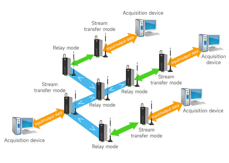
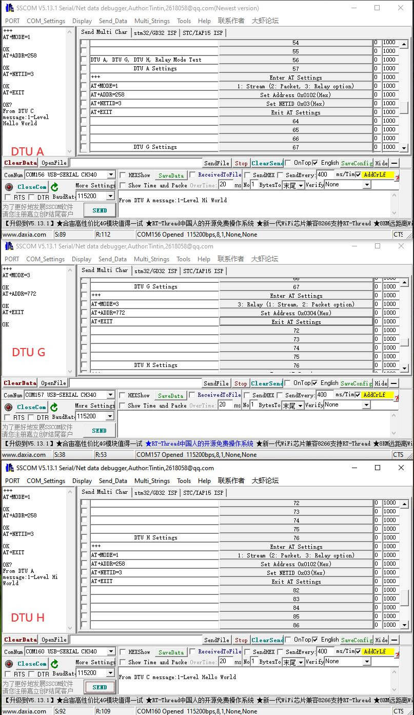
First-level Relay
- First-level relay refers to the transmission mode in which multiple DTU devices are composed of LoRa networks, and only one DTU device is forwarded as a node in relay mode to forward data streams from other DTU devices.
- After the DTU A, G, and H devices form another first-level relay LoRa network, and after setting DTU G (using AT+MODE=3rn instructions) to relay mode, DTU G only forwards the data stream of DTU A and DTU H, and the interface does not output the data stream.
- Under the relay mode LoRa communication network, the communication device in stream mode or packet mode has the same parameters except for the NETID parameter, and the NETID parameter of DTU A and H will be used as the address of the relay node, such as the NETID of DTU A, H forms the address of DTU G Hex: 0x0304 (Decimal: 772).
| Parameters | DTU A | DTU G | DTU H |
| Spreading Factor | 7 | 7 | 7 |
| Bandwidth | 0: 125KHz | 0: 125KHz | 0: 125KHz |
| Code Rate | 1: 4/5 | 1: 4/5 | 1: 4/5 |
| NETID | Hex: 0x03 (Decimal: 3) | Ignore | Hex: 0x04 (Decimal: 4) |
| Operating Mode | 1: Stream Mode | 3: Relay Mode | 1: Stream Mode |
| Address | Hex: 0x0102 (Decimal: 258) | Hex: 0x0304 (Decimal: 772) | Hex: 0x0102 (Decimal: 258) |
| Channel | 18 (Hex:0x12) | 18 (Hex:0x12) | 18 (Hex:0x12) |
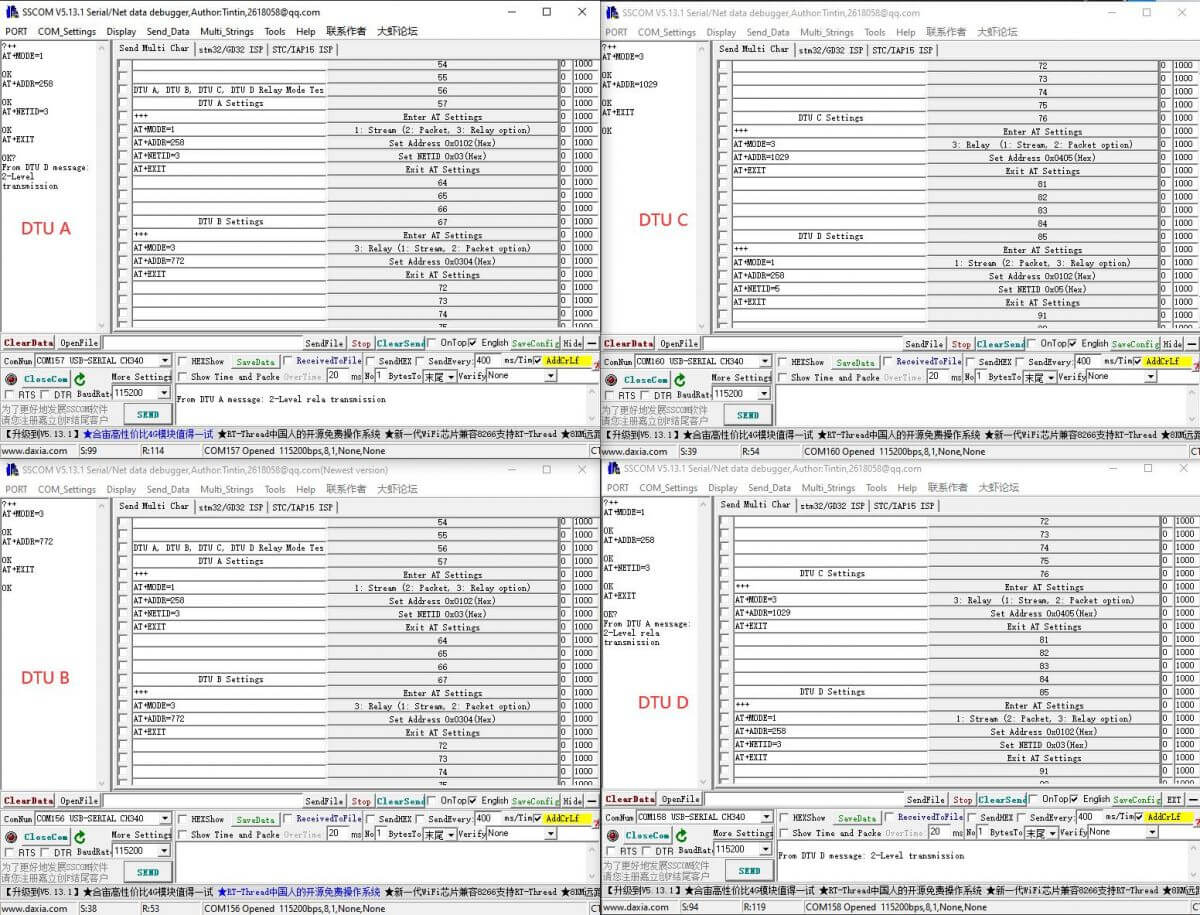
Second-level Relay
- Second-level relay refers to the transmission mode in which multiple DTU devices are composed of LoRa networks, and only two DTU devices are forwarded as nodes in trunk mode to forward data streams from other DTU devices.
- In the above figure, DTU A, B, C, and D devices form a secondary relay LoRa network, respectively set DTU B, C (use AT+MODE=3rn instruction) to relay mode, DTU B, C only forwards DTU A and DTU D data streams, and the interface does not output data streams.
| Parameters | DTU A | DTU B | DTU C | DTU D |
| Spreading Factor | 7 | 7 | 7 | 7 |
| Bandwidth | 0: 125KHz | 0: 125KHz | 0: 125KHz | 0: 125KHz |
| Code Rate | 1: 4/5 | 1: 4/5 | 1: 4/5 | 1: 4/5 |
| NETID | Hex: 0x03 (Decimal: 3) | Ignore | Ignore | Hex: 0x05 (Decimal: 5) |
| Operating Mode | 1: Stream Mode | 3: Relay Mode | 3: Relay Mode | 1: Stream Mode |
| Address | Hex: 0x0102 (Decimal: 258) | Hex: 0x0304 (Decimal: 772) | Hex: 0x0405 (Decimal: 1029) | Hex: 0x0102 (Decimal: 258) |
| Channel | 18 (Hex: 0x12) | 18 (Hex: 0x12) | 18 (Hex: 0x12) | 18 (Hex: 0x12) |
Other Functions
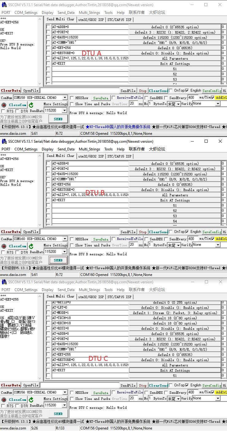
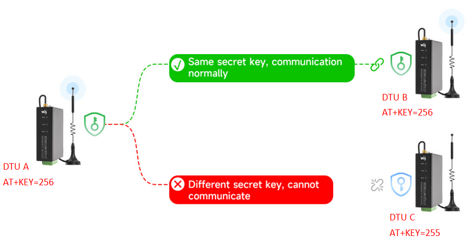
Encryption
- The encryption function encrypts the DTU plaintext data using the AES algorithm and then transmits it through LoRa to achieve the purpose of wireless communication security.
- Use AT+KEY=65535 (default 0: disable encryption, 1~65535: key value) command to set the encryption key.
- After encryption is enabled, DTUs with the same key value can communicate normally, but DTUs with different key values cannot communicate normally.
- In the figure, after setting the same key, DTU A and B communicate normally, but DTU C with different key values outputs garbled characters.
RSSI Output
- RSSI, Received signal strength indication, used to evaluate signal quality, improve communication network, distance measurement, etc.
- After using AT+RSSI=1 (default 0: disabled) to enable the RSSI function, as shown in the figure below, each output data packet will follow a hexadecimal RSSI value.
LBT (Listen Before Talk)
- LBT (Listen Before Talk) means that the module actively monitors the channel environment noise before sending. This function can improve the communication success rate and anti-collision processing of DTU in harsh environments.
- Use AT+LBT=1 (default 0: disabled) to enable the LBT function, and actively monitor the channel noise before sending the data packet, if it exceeds the threshold, the sending will be delayed, the maximum delay is two seconds, and the sending will be forced after more than two seconds.
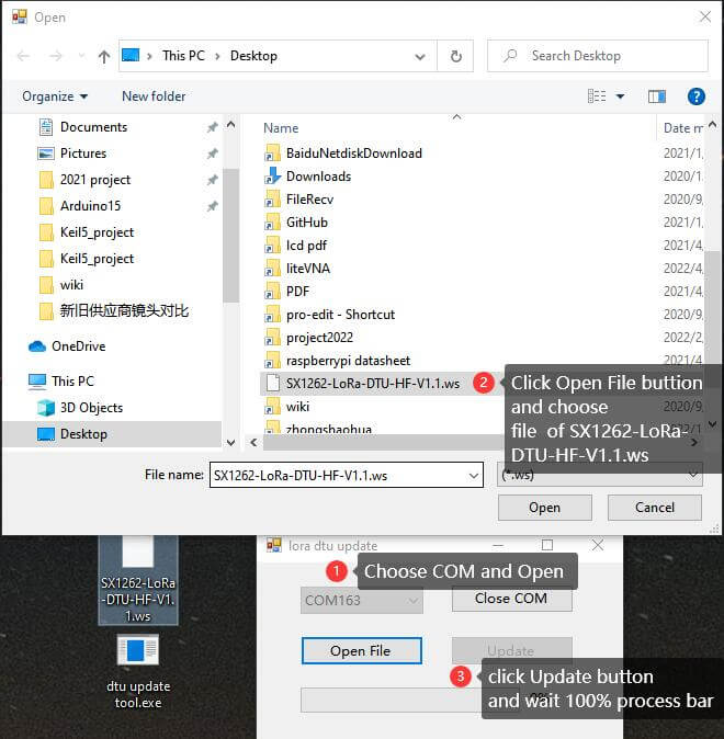
Upgrade Firmware
- The default firmware update interface is RS485, other interfaces are not supported.
- Press the KEY button within three seconds after powering on, and the TXD and RXD lights will flash once, and enter the firmware update mode, use a USB to RS485 tool (such as USB TO RS485) to connect DTU and PC.
- Download and open the firmware update software, open the corresponding COM, select the latest firmware such as SX1262-LoRa-DTU-HF-V1.1.ws, and click the Update button to update.