- sales/support
Google Chat:---
- sales
+86-0755-88291180
- sales01
sales@spotpear.com
- sales02
dragon_manager@163.com
- support
tech-support@spotpear.com
- CEO-Complaints
zhoujie@spotpear.com
- Only Tech-Support
WhatsApp:13246739196
- Purchase/Shipping/Refund
WhatsApp:13424403025
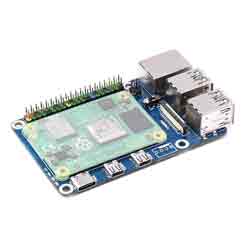
Raspberry Pi CM4-to-Pi4-Adapter User Guide
Introduction
This is a CM4 To Pi 4B Adapter for Raspberry Pi and is an alternative solution for Raspberry Pi 4B. Onboard 4 x USB3.0 ports, Gigabit Ethernet port, PoE header, and so on.
Features
- Onboard standard CM4 connector, support access to CM4 Lite / eMMc series boards with Quad Core Cortex A72 64-bit processor, more powerful performance
- Easily compatible with the interfaces of Raspberry Pi 4B board, the DISPLAY port position is inconsistent with the main board of Raspberry Pi 4B
- Onboard 4-ch USB 3.0 ports, compatible with USB 2.0 / 1.1 transmission
- Onboard RJ45 Gigabit Ethernet port, 10 / 100 / 1000 M adaptive
- Onboard PoE header, for connecting PoE HATs
- DSI interface is DSI1
- USB Type C interface is for the power supply or can be used as the USB SLAVE interface for programming images
- Do not connect to other devices when using the micro USB port to program the image for ensuring the power supply of CM4
- CM4 must be provided by 5V 2A, or it will shut down, lower frequency, etc.
Dimensions
CM4-to-Pi4-Adapter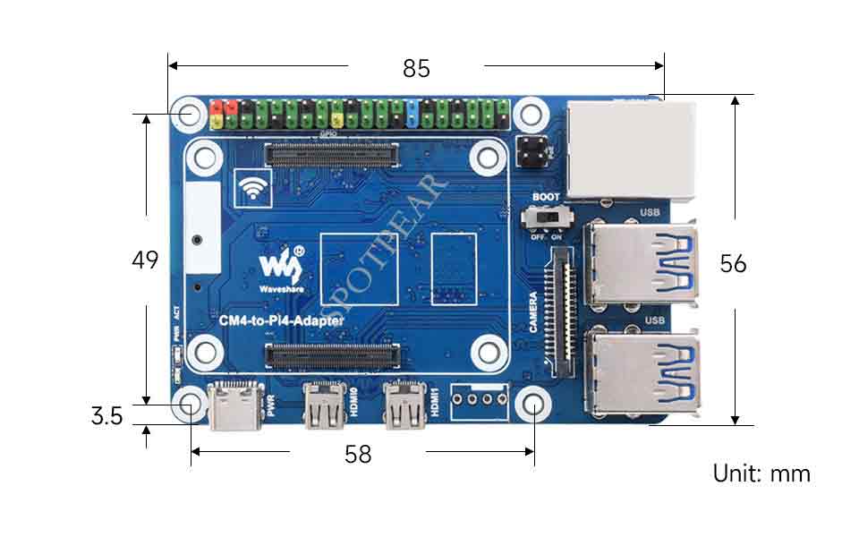
Compute_Module 4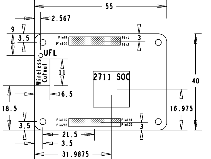
Onboard Resources
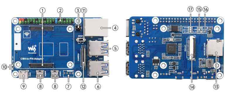
| No. | Name | Description | |
| 1 | CM4 socket | for all variants of Compute Module 4 | |
| 2 | 40PIN GPIO header | for connecting to all HATs | |
| 3 | PoE | Support access to PoE HAT | |
| 4 | Gigabit Ethernet port | RJ45 Gigabit Ethernet port, support 10 / 100 / 1000M network access | |
| 5,6 | USB3.0 interface | 4x USB3.0 interface, support USB devices | |
| 7 | FAN header | Connect to the cooling fan, does not support speed regulation and speed measurement only supports 5V fan (not soldering by default) | |
| 8 | HDMI interface | 2 x Micro HDMI interface, supports 4K 30fps output | |
| 9 | USB Type C | 5V/2.5A power supply, can also be used as an eMMC programming interface | |
| 10 | LED indicator | Indicating the working status of the Raspberry Pi | |
| 11 | BOOT | ON:CM4 USB Type C booting guide OFF: eMMC or SD card boot guide | |
| 12 | CAM interface | MIPI CSI interface | |
| 13 | Micro SD card slot | For connecting to a Micro SD card with the system, only for the Lite version | |
| 14 | DISP1 interface | MIPI DSI interface, DISP1 interface | |
| 15 | IO-VREF selection | CM4 IO logic voltage switch 3.3V or 1.8V | |
| 16 | Function pin | RUN: CM4 running status pin GL-EN: Power supply enable pin | |
| 17 | System function switch | BT_DIS: Bluetooth disabled, only for CM4 with antenna WiFi_DIS: WiFi disabled, only for CM4 with antenna WP_DIS: EEPROM write protection |
Note
Do not plug and unplug any devices when powering on.
Image Programming
- Write Image for Compute Module Boards eMMC version
- Write Image for Compute Module Boards Lite version
Fan Header
The default is no welding, without speed regulation and speed measurement, controlled by GPIO18 (BCM code).
CSI
Configuration File
CSI and DSI are disabled by default. When using the camera and DSI, it will occupy three I2C devices: I2C-10, I2C-11, and I2C-0.
- Open a terminal and run the following commands:
wget https://www.waveshare.com/w/upload/7/75/CM4_dt_blob_Source.zip
 unzip -o  CM4_dt_blob_Source.zip -d ./CM4_dt_blob_Source
 sudo chmod 777 -R CM4_dt_blob_Source
 cd CM4_dt_blob_Source/
 sudo  dtc -I dts -O dtb -o /boot/dt-blob.bin dt-blob-disp0-double_cam.dts
 #If you need to restore, please delete the corresponding dt-blob.bin: sudo rm -rf /boot/dt-blob.bin
 # After execution, turn off the power and restart the CM4
Record Test
Connect the cameras:
1: Please power off the IO Board first before connecting.
2: Connect the power adapter after connecting the cameras and DSI display.
3: Wait a few seconds before the screen boot up.
4: If the DSI LCD cannot display, please check if you have added /boot/dt-blob.bin. If there already has the dt-blob.bin, just try to reboot.
Old Version (Buster)
Run the "raspi-config" in the camera, choose Interfacing Options->Camera->Yes->Finish-Yes, reboot the system, open "enable camera", and then reboot to save the change.
- Test the Cameras:
Test camera:
sudo raspivid -t 0 -cs 0
New Version (Bullseye)
If you are using the latest Raspberry Pi OS (Bullseye):
#Use dual cameras in the new system
#Remove "camera_auto_detect=1" in config.txt
#camera_auto_detect=1

#Add
dtoverlay=imx219,cam0

#imx219 is the model of the camera sensor, and it also supports other sensors.
dtoverlay=ov5647,cam0
dtoverlay=imx219,cam0
dtoverlay=ov9281,cam0
dtoverlay=imx477,cam0

#Then reboot
reboot

#Open the camera
libcamera-hello -t 0
or
libcamera-hello

#Other commands:
#Check whether the camera is detected
libcamera-hello --list-cameras

#Open the corresponding camera
libcamera-hello  --camera 0

#Take a picture
libcamera-jpeg -o test.jpg

#You can add "--camera" to specify the camera
More instructions click me.
Please refer to Raspberry Pi Manual.