


- sales/support
Google Chat:---
- sales
+86-0755-88291180
- sales01
sales@spotpear.com
- sales02
dragon_manager@163.com
- support
tech-support@spotpear.com
- CEO-Complaints
zhoujie@spotpear.com
- Only Tech-Support
WhatsApp:13246739196
- Purchase/Shipping/Refund
WhatsApp:13424403025
Raspberry Pi Pico-ResTouch-LCD-3.5 User Guide
Documents
Demo codes
Software
Download Firmware
- MicroPython Firmware Download

- C_Blink Firmware Download

Text Tutorial
Basic Introduction
MicroPython Series
- 【MicroPython】 machine.Pin Function
- 【MicroPython】 machine.PWM Function
- 【MicroPython】 machine.ADC Function
- 【MicroPython】 machine.UART Function
- 【MicroPython】 machine.I2C Function
- 【MicroPython】 machine.SPI Function
- 【MicroPython】 rp2.StateMachine
C/C++ Series
Overview
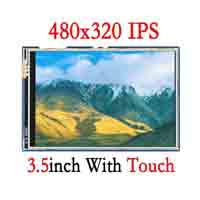
3.5inch Touch Display Module For Raspberry Pi Pico, 65K Colors, 480 x 320 Pixels, Resistive Touch Controller XPT2046, ILI9488 Driver, Using SPI Bus.
Features
- 480 × 320 resolution, IPS screen, 65K colors, clear and colorful displaying effect.
- Dedicated touch controller, bringing more smooth touching effect than AD-controlled solutions.
- MicroSD card slot for storing images and direct displaying them easily.
- Programmable backlight control, saving more power.
- Comes with complete resources and manual (Raspberry Pi Pico C/C++ and MicroPython demos).
Specifications
- Operating voltage: 5V
- Resolution: 480 × 320 pixels
- Communication interface: 4-wire SPI
- Display size: 73.44 × 48.96 mm
- Display panel: IPS
- Pixel size: 0.153 × 0.153 mm
- Driver: ILI9488
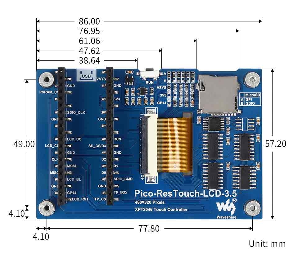
- Dimensions: 86.00 × 57.20 mm
- Touch controller: ILI9488
Pinout
The built-in controller used by Pico-ResTouch-LCD-3.5 is ILI9488, which is a 480 x 320 pixel RGB LCD controller. The test demo uses RGB565 format. The LCD is a 16Bits parallel port screen, and the hardware uses a parallel port to serial chip, which can greatly save the GPIO port, and the maximum SPI writing speed tested is 60MHz.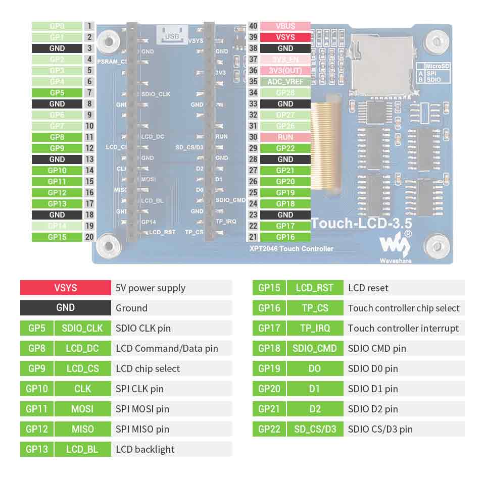
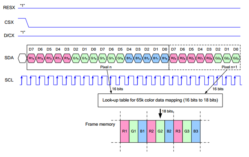
Note: The difference with the traditional SPI protocol is that since most of them are used for display, the data wire sent from the slave to the host is hidden. For details, please refer to the Datasheet Page 55 (8.4 Serial Interface) chapter for this table.
RESX (LCD_RST): reset, usually set to 1 and is pulled low when the module is powered on.
CSX (LCD_CS): chip selection, the chip can be enabled when the voltage of CS is low.
D/CX (LCD_DC): chip data/command control pin, writing command when DC = 0, writing data when DC=1.
SDA (MOSI): transmitted data, that is, RGB data.
SCL (CLK): SPI communication clock.
For SPI communication, the data is transmitted in timing order, that is, the combination of CPHA and CPOL.
The level of CPHA determines whether the serial synchronization clock is collected on the first clock transition edge or the second clock transition edge. When CPHA = 0, data acquisition is performed on the first transition edge.
The level of CPOL determines the idle state level of the serial synchronous clock. CPOL = 0, which is a low level.
As can be seen from the figure, when the first falling edge of SCLK starts to transmit data, 8bit data is transmitted in one clock cycle, using SPI0, bit-wise transmission, high-order first, and low-order last.
Dimension
Get Started with Pico
Hardware connection
Please take care of the direction when you connect Pico, an USB port is printed to indicate. You can also check the pin of Pico and the LCD board when connecting.
You can connect the display according to the table.
| LCD | Pico | Description |
| VCC | VSYS | Power input |
| GND | GND | GND |
| SDIO_CLK | GP5 | SCK pin of SDIO interface clock input for the slave device. |
| LCD_DC | GP8 | Data/Command pin (High: data; Low: command) |
| LCD_CS | GP9 | Chip select pin of LCD (Low active) |
| LCD_CLK | GP10 | CLK pin of LCD communication, clock input for slave device |
| MOSI | GP11 | SPI MOSI pin |
| MISO | GP12 | SPI MISO pin |
| LCD_BL | GP13 | LCD backlight control |
| LCD_RST | GP15 | LCD reset pin (Low active) |
| TP_CS | GP16 | Touch controller chip select (Low active) |
| TP_IRQ | GP17 | Touch controller interrupt pin (Low active) |
| SDIO_CMD | GP18 | SDIO CMD pin |
| D0 | GP19 | SDIO D0 pin |
| D1 | GP20 | SDIO D1 pin |
| D2 | GP21 | SDIO D2 pin |
| SD_CS/D3 | GP22 | SDIO CS/D3 pin |
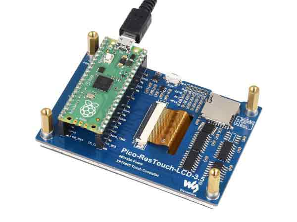
Pay attention to the connection direction of the Pico, the USB of the Pico should be in the same direction as the MicroSD card.
Setup environment
- We test the demo with Arduino IDE, VScode(cmake), Thonny, click to download the related IDE, and open Arduino IDE, Thonny after installation.
1. Please install Pico SDK in Arduino IDE, click Tools->Board->Boards Manager in the menu bar and search for Raspberry Pi Pico, find the corresponding library and click Install to install it, as shown in the figure below: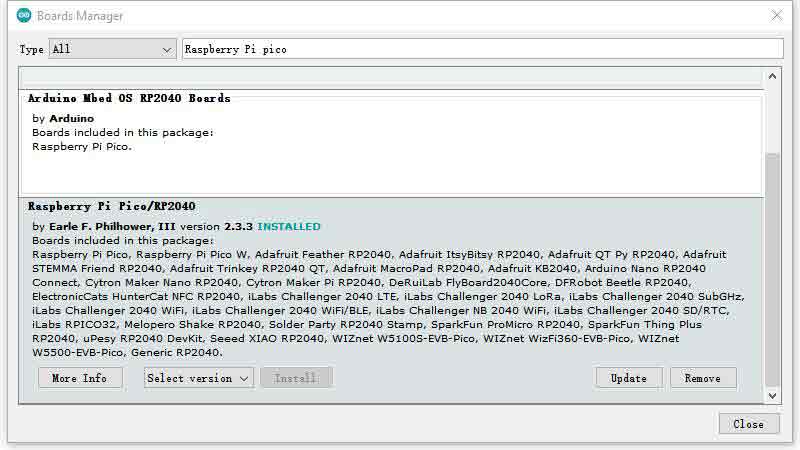
2. Please refer to The C/C++ SDK, 9.2. Building on MS Windows in GET-START document for the compilation environment of VScode(Cmake).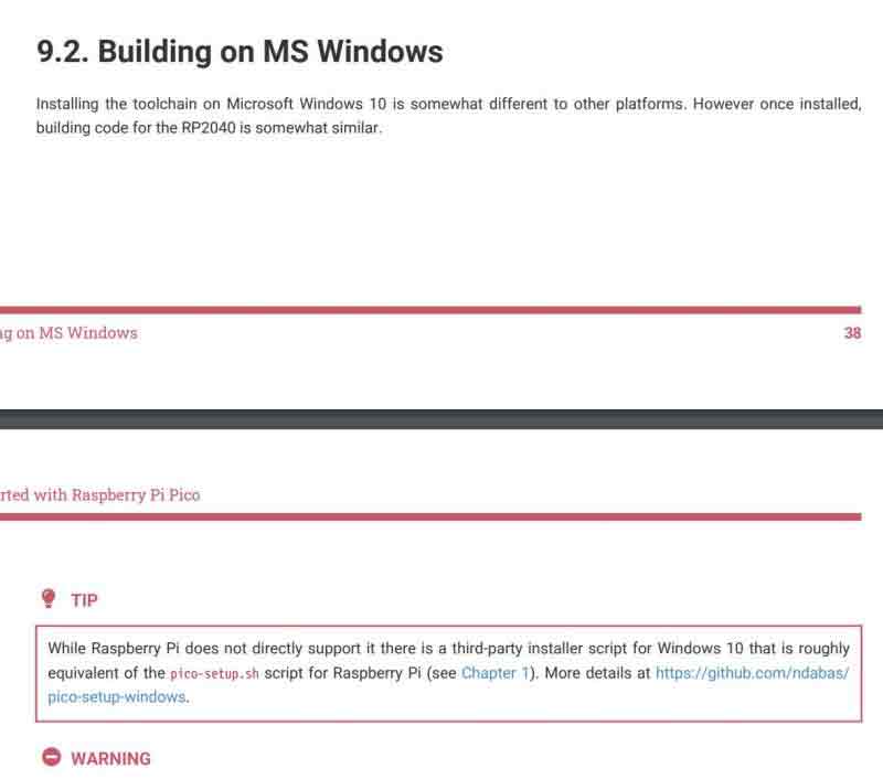
3. Please refer to the official micropython document to set up the environment, and select the Raspberry Pi Pico device in Thonny's Tools->Options->Interprete. As shown below: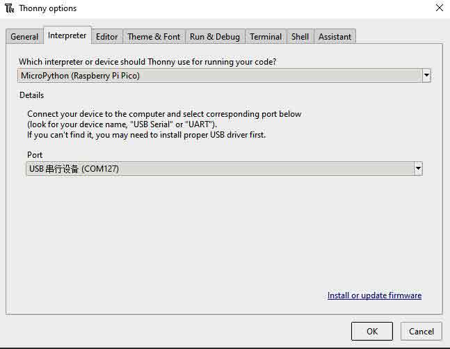
Download Demo codes
- Click to download the sample demo.
- Please open the VScode (Cmake) project with VScode software.
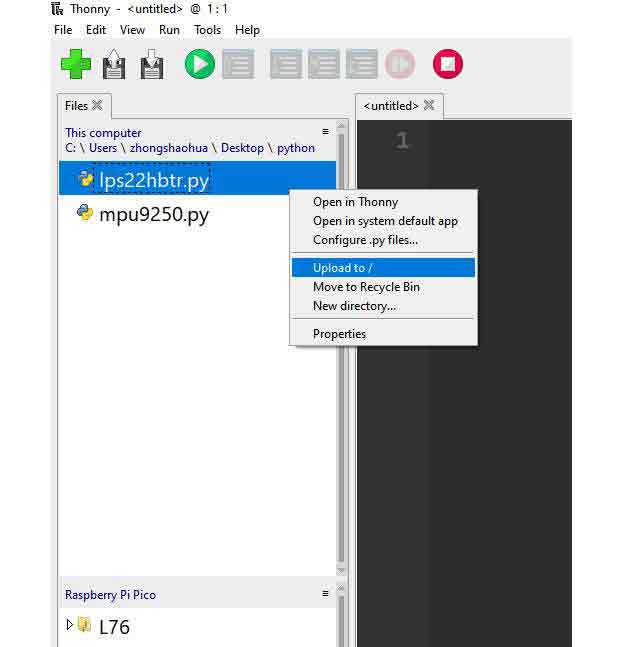
- Unzip the sample demo, and click ".ino" to open the Arduino demo. Please upload the Micropython sample demo to Pico document system. As shown below:
Run the Demo codes
Arduino
1. Open Arduino IDE or ".ino" sample program. Click "Tools->Board->Raspberry Pi Pico" in the Tools. As shown below.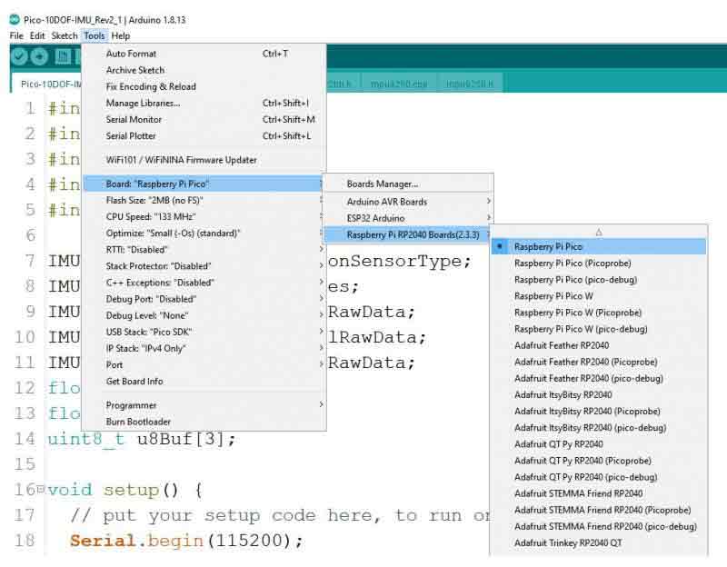
2. Install the TFT_eSPI library, click Tools->Manage Library in the menu bar, search for TFT_eSPI and click Install.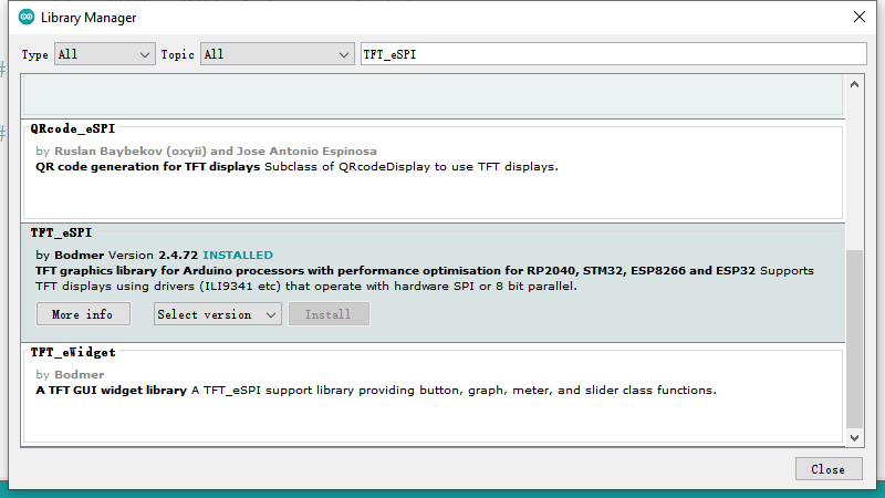
3. To configure the driver file, open the Arduino library file directory, usually in C:\Users\xxxx\Documents\Arduino\libraries\TFT_eSPI\ , for ResTouch-LCD-3.5, put the TFT_eSPI library (User_Setups\Setup60_RP2040_ILI9341.h) (User_Setup_Select.h) ) with the files in the sample program folder Arduino\ResTouch-LCD-3.5, and the same for ResTouch-LCD-2.8, as shown in the figure.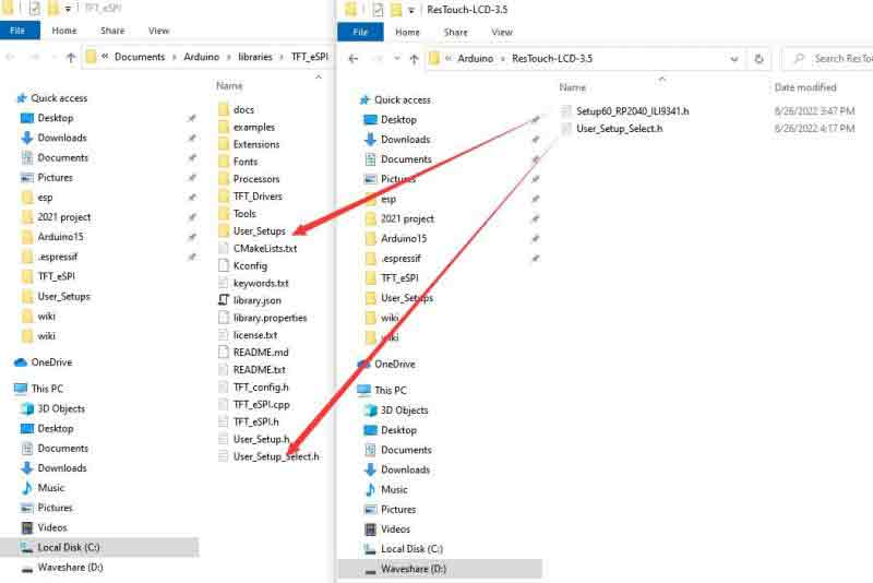
4. Select the example program under File-Examples->TFT_eSPI->480*320 in the menu bar, and then click Upload under Edit to download the code to Pico.
VScode(Cmake)
- Open the c project with VScode, and then compile to download.
Micropython
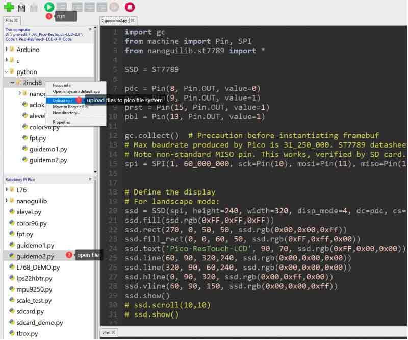
- Open Thonny IDE, and save the code under "python/2inch8/" to the Pico file system.And the same for ResTouch-LCD-3.5, As shown below:
Code Analysis
The example will display strings, figures, images, and finally the touchpad function. The C demo is for Pico-ResTouch-LCD-2.8 and Pico-ResTouch-LCD-3.5. In the main function, we place the three main functions in order and place TP_DrawBoard(); in an infinite loop to achieve the above function.
GUI_Show();
LCD_Show_bmp(Bmp_ScanDir , Lcd_ScanDir);
TP_DrawBoard();
Note that if you want to test the LCD_ShowBMP example, you need to copy the picture from the PIC folder to the root directory of a micro SD card, and insert the SD card into the slot in the backside of the LCD. Then run the examples.
- The micro SD card should in FAT format, and the resolution of the pictures used should be the same as the LCD, for a 2.8inch LCD, it is 320 × 240, and 480 × 320 for a 3.5inch LCD. 24bit BMP.
The LCD controller is ILI9488, we need to initialize the controller at the first, which is done in LCD_Driver.c file, and being called in lcd_test.c file.
System_Init();//System intialize, configure serial port and SPI interface...
  LCD_SCAN_DIR Lcd_ScanDir = SCAN_DIR_DFT; //Set the scan mode
  LCD_Init( Lcd_ScanDir, 200);//Initialize LCD panel, confirm the scan mode and the brightness
GUI functions are all be saved in LCD_GUI.c file, you can call them to draw the display.
- Draw point
void GUI_DrawPoint(POINT Xpoint, POINT Ypoint, COLOR Color,
                   DOT_PIXEL Dot_Pixel, DOT_STYLE DOT_STYLE)
- Draw line (dotted or solid)
void GUI_DrawLine(POINT Xstart, POINT Ystart, POINT Xend, POINT Yend,
                  COLOR Color, LINE_STYLE Line_Style, DOT_PIXEL Dot_Pixel)
- Draw a rectangle (empty of filled)
void GUI_DrawRectangle(POINT Xstart, POINT Ystart, POINT Xend, POINT Yend,
                       COLOR Color, DRAW_FILL Filled, DOT_PIXEL Dot_Pixel)
- Draw a circle (empty of filled)
void GUI_DrawCircle(POINT X_Center, POINT Y_Center, LENGTH Radius,
                    COLOR Color, DRAW_FILL  Draw_Fill , DOT_PIXEL Dot_Pixel)
- Display character
void GUI_DisChar(POINT Xpoint, POINT Ypoint, const char Acsii_Char,
                 sFONT* Font, COLOR Color_Background, COLOR Color_Foreground)
- Display string
void GUI_DisString_EN(POINT Xstart, POINT Ystart, const char * pString,
                      sFONT* Font, COLOR Color_Background, COLOR Color_Foreground )
- Display number
void GUI_DisNum(POINT Xpoint, POINT Ypoint, int32_t Nummber,
                sFONT* Font, COLOR Color_Background, COLOR Color_Foreground )
- Display time
void GUI_Showtime(POINT Xstart, POINT Ystart, POINT Xend, POINT Yend,
                  DEV_TIME *pTime, COLOR Color)
In the example, this demo shows that the BMP picture first reads the picture data in the BMP format on the SD card through the SPI protocol and displays it.
In lcd_test.c file, we use two functions for display picture:
SD_Init();//Initialize SD card
LCD_Show_bmp(bmp_scan_dir,lcd_scan_dir);//Display BMP picture
These functions are written in LCD_Bmp.c, actually read the picture data in the BMP format with a specific file name from the SD card and then call the display function written by ourselves to "express" the data as an image again.
In LCD_Touch.c file:
TP_Init( Lcd_ScanDir );//Initialize touch panel and set the scan mode
TP_GetAdFac();//Calibrate the display
TP_Dialog();//Clear
TP_DrawBoard();//Enable the drawing board
There will be five colors on the right side of the screen, the default color is black, touch them to select the pen color; click the AD button, and follow the on-screen prompts to click the red + sign to calibrate the screen; click the CLEAR button in upper right corner to clear the drawing board.
The touch test uses four sets of calibration values by default, which can meet the brush operations in four directions. There are five color choices on the right, and the default brush size is 9 pixels.
The function for touching is saved in the LCD_Touch.c file.
There are five fonts available.
   Width 5, Height 8    font8
   Width 7,Height 12    font12
   Width 11,Height 16    font16
   Width 14,Height 20    font20
   Width 17,Height24    font24
- If you need characters in different sizes and fonts, you can generate the font library you want by the font extraction software provided in the #Resources.
- In fact, you can use the Image2Lcd software to convert a picture to arrays and display them by the functions in the example.
- Datasheet of chips are provided, you can read them for more information.