


- sales/support
Google Chat:---
- sales
+86-0755-88291180
- sales01
sales@spotpear.com
- sales02
dragon_manager@163.com
- support
tech-support@spotpear.com
- CEO-Complaints
zhoujie@spotpear.com
- Only Tech-Support
WhatsApp:13246739196
- Purchase/Shipping/Refund
WhatsApp:13424403025
Banana pi ------ Getting Started with M2 Zero
BPI-M2 Zero
- Read more about : Banana Pi BPI-ZERO
BPI-M2 Zero
Banana Pi M2 Zero is an ultra compact single board computer measures only 60mm*30mm. It uses quad-core Cortex A7 allwinner H2+ processor, with 512MB RAM memory. It's ideal for light-weight systems with some space-limited applications. Like other members of Banana Pi, it supports both linux and android operating system.
Key Features
- Quad Core ARM Cortex A7 CPU H2+
- 512MB SDRAM.
- WiFi (AP6212) & Bluetooth onboard.
- Mini HDMI.
Development
Basic Development
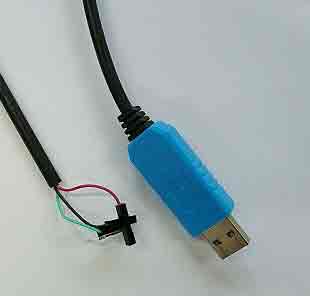
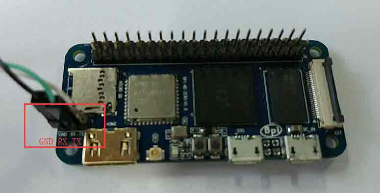
Prepare to develop
 * Prepare 8G/above TF card, USB-Serial interface, PC with Ubuntu System
 * Using your USB-Serial Connect debug console on M2 Zero
Install Linux Image on M2 Zero
Download latest Linux image11111111111111111, default login user/password is pi/bananapi or root/bananapi.
Install Image to SDcard on Linux PC with bpi-tools
- 1. Install bpi-tools on your system
   $ apt-get install pv
   $ curl -sL https://github.com/BPI-SINOVOIP/bpi-tools/raw/master/bpi-tools | sudo -E bash
- If you can't access this URL or any other problems, please go to Balena Etcher and install this tools manually.
- 2. Insert your SDcard into your PC
$ bpi-copy xxx.img /dev/sdx
Install Image to SDcard with Ether on Windows, Linux and MacOS
Balena Etcher is an open source project by Balena, Flash OS images to SD cards & USB drives
Install Image to EMMC with SD Ubuntu
- 1.Prepare a sd which is installed ubuntu image and bootup with sdcard
- 2.Copy emmc image to udisk, plug in board, then mount udisk.
- 3.After mount udisk, use command "bpi-copy xxx-emmc-xxx.img" to install image on Emmc.
- 4.After success install, power off the board, eject the sdcard and poweron with emmc boot.
Update your image
- 1. Get the m2 zero bsp source code
$ git clone https://github.com/BPI-SINOVOIP/BPI-M2P-bsp-4.4
- 2. Build the source code according to the README.md, and update the packages to the sdcard with bpi image flashed.
Advanced Development
How to create an image
- Prepare a SD card which have installed system(Ubuntu/Raspbian/..)
- Boot your SD card with M2 Zero, after M2 Zero finish starting, copy your files and config your system, then poweroff M2 Zero. [If you don't want to config your system, you can skip this step]
- Plug your SD card in PC(which is running Linux), "cd /media", then "ln -s <your account> pi"
- Execute "bpi-migrate -c bpi-m2z.conf -c ubuntu-mate-from-sd.conf -d /dev/sdx"
- Then you could get your own image now
OTG
1. On M2 Zero console:
- Execute "./adbd.sh", then execute "ps -ax | grep adbd" to see if adbd is set up
2. On PC terminal:
- If adbd was succeed to set up, insert OTG-USB interface to M2 Zero and PC(with Ubuntu system)
- Execute "adb devices" to see if PC has recognised M2 ZeroP OTG
- If yes, we could execute "adb shell" to connect M2 Zero by adb now
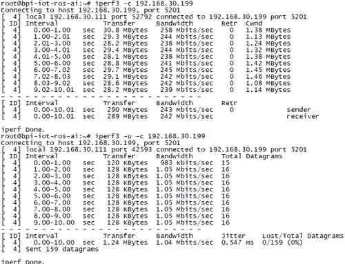
USB Ethernet
- Prepare a USB to OTG wire, usb ethernet adapter
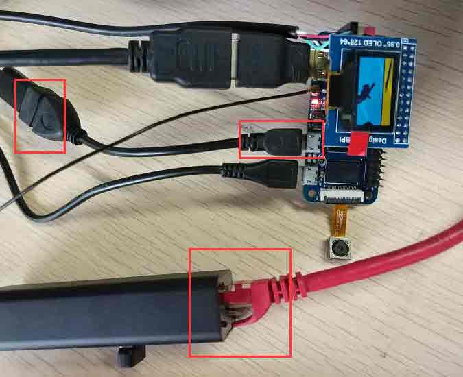
- Use iperf3 to test network
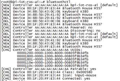
Bluetooth
- Use bluetoothctl tool to operate BT
- Execute "bluetoothctl"
- If you don't know how to use bluetoothctl, type "help", you will see more commands
- Execute these commands:
WiFi Client
You have two ways to setup WiFi Client
1. Use commands to setup WiFi client
- ip link set wlan0 up
- iw dev wlan0 scan | grep SSID
- vim /etc/wpasupplicant/wpa_supplicant.conf
network={
ssid="ssid"
psk="password"
priority=1
}
- wpa_supplicant -iwlan0 -c /etc/wpa_supplicant/wpa_supplicant.conf
- dhclient wlan0
2. Use UI interface to setup WiFi Client
Clear boot
- git clone https://github.com/BPI-SINOVOIP/BPI-files/tree/master/SD/100MB
- bpi-bootsel BPI-cleanboot-8k.img.gz /dev/sdX
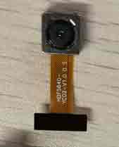
Camara function
We use HDF5640 camara.
Guvcview
- Use your UI interface to operate camara
- Applications -> Sound & Video -> guvcview
Shell
- We also have built-in command in /usr/local/bin to test camara
- "./test_ov5640_image_mode.sh" to test picture taking function
- "./cameratest.sh" to test video recording function
Display
How to change display resolution
For Example: we change M2Z HDMI display 1080P.
1. First, mount /dev/mmcblk0p1 /mnt, then enter to /mnt/bananapi/bpi-m2z/linux, find "sys_config.fex";
2. "vim sys_config.fex", change "screen0_output_mode = 5" to "screen0_output_mode = 10"
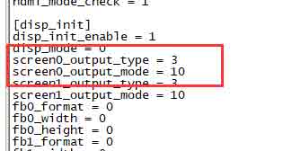
3. After save changed, use "fex2bin" command to transfer sys_config.fex to bin file, "fex2bin sys_config.fex script.bin ", reboot.
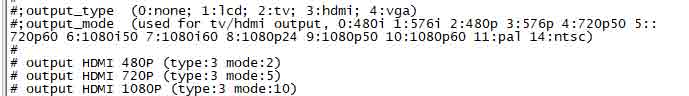
parameters meaning:
BPI-Tools
Install Bpi-tools
- Execute "curl -sL https://github.com/BPI-SINOVOIP/bpi-tools/raw/master/bpi-tools | sudo -E bash - "
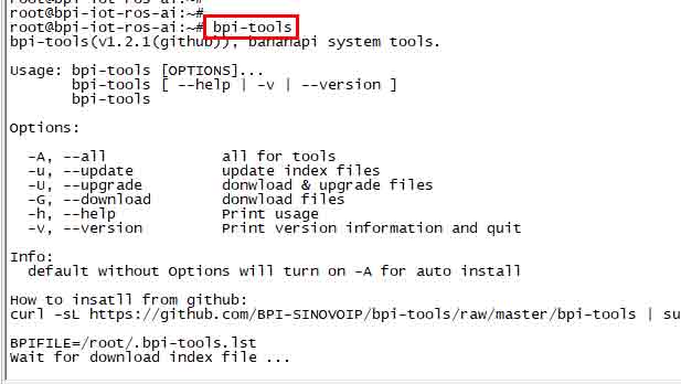
Update Bpi-tools
- Execute "bpi-tools"
RPi.GPIO
Install RPi.GPIO
- Execute "git clone https://github.com/BPI-SINOVOIP/RPi.GPIO
- after clone the repo, cd RPi,GPIO
- Execute "sudo apt-get update"
- Execute "sudo apt-get install python-dev python3-dev"
- Execute "sudo python setup.py install" or "sudo python3 setup.py install" to install the module
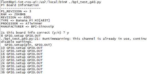
Using RPi.GPIO
- cd /usr/local/bin
- Execute "./bpi_test_g40.py" to test RPi.GPIO
WiringPi
- GitHub: https://github.com/BPI-SINOVOIP/BPI-WiringPi2.git
- We also have built-in test command in "/usr/local/bin"
How to Update WiringPi
- Execute "bpi-update -c pkglist.conf"
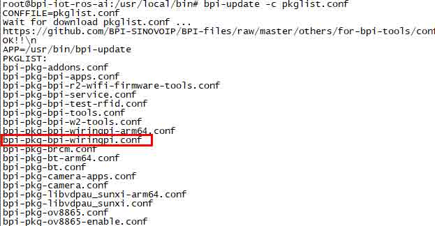
- Execute "bpi-update -c bpi-pkg-bpi-wiringpi.conf"
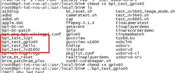
RGB 1602 LCD
- Execute "/usr/local/bin/bpi_test_lcd1602.sh"
0.96 Inch OLED Display
- Execute "/usr/local/bin/bpi_test_52pi.sh"
8x8 RGB LED Martix
- Firstly you need a GPIO Extend Board for 8x8 LED Martix
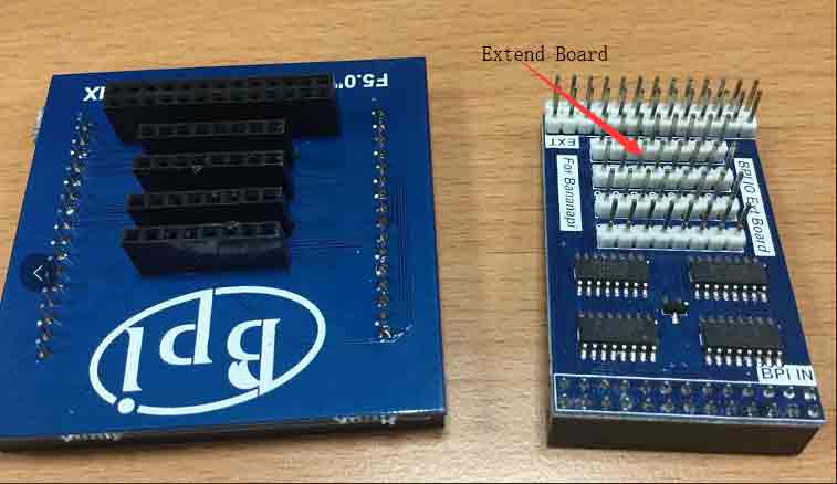
- Execute "/usr/local/bin/bpi_test_gpio40.sh"