


- sales/support
Google Chat:---
- sales
+86-0755-88291180
- sales01
sales@spotpear.com
- sales02
dragon_manager@163.com
- support
tech-support@spotpear.com
- CEO-Complaints
zhoujie@spotpear.com
- Only Tech-Support
WhatsApp:13246739196
- Purchase/Shipping/Refund
WhatsApp:13424403025
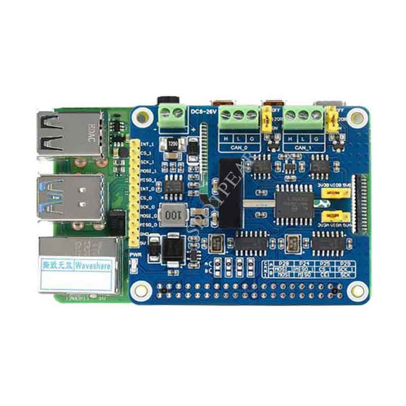
Raspberry Pi 2-CH CAN FD HAT User Guide
Introduction
This is a 2-Channel CAN bus expansion HAT designed for Raspberry Pi, supports CAN FD (CAN with Flexible Data-Rate), the speed is higher than the traditional 1Mbps of CAN2.0, features multi onboard protection circuits, high anti-interference capability, and stable operation. It suits for fields such as automotive devices or industrial automation.
Features
- Standard Raspberry Pi 40PIN GPIO extension header, supports Raspberry Pi series boards
- Supports both traditional CAN2.0 and CAN FD protocols, up to 8Mbps data rate
- Breakout SPI control pins, for connecting with host control boards like STM32/Arduino
- Onboard electrical isolation, up to 5KV isolated voltage, high anti-interference capability, stable operation
- Onboard lighting proof, ESD, short circuit protection, more safe communication
- Onboard voltage translator, select 3.3V/5V operating voltage by jumper
- Onboard 120Ω terminal resistor, configured by jumper
- Comes with development resources and manual (examples for Raspberry Pi/Arduino)
Specifications
- CAN controller: MCP2518FD
- CAN transceiver: MCP2562FD
- Communication interface: SPI (two channels independent SPI by default, swith to one channel SPI by soldering)
- Power supply: external power input terminal, or Raspberry Pi
- Power input terminal voltage: DC 8~26V
- Operating voltage: 5V
- Logic level: 3.3V/5V
- Dimensions: 65.0 x 56.5 mm
Interfaces
| PIN | Raspberry Pi (BCM2835) | Raspberry Pi (WPI) | Description |
| 5V | 5V | 5V | 5V Power input |
| GND | GND | GND | Ground |
| MISO_0 | 9 (MISO) | 13 (MISO) | SPI_0 Data output |
| MOSI_0 | 10 (MOSI) | 12(MOSI) | SPI_0 Data input |
| SCK_0 | 11 (SCK) | 14 (SCK) | SPI_0 Clock input |
| CS_0 | 8 (CE0) | 10 (CE0) | CAN_0 Chip select |
| INT_0 | 25 | 6 | CAN_0 Interrupt Pin |
| MISO_1 | 9/19 (MISO) | 13/24 (MISO) | SPI_1 Data output |
| MOSI_1 | 10/20 (MOSI) | 12/28 (MOSI) | SPI_1 Data input |
| SCK_1 | 11/21(SCLK) | 14/29 (SCLK) | SPI_1 Clock input |
| CS_1 | 7(CE1)/26 | 11(CE1)/25 | CAN_1 Chip select |
| INT_1 | 16 | 27 | CAN_1 Interrupt Pin |
Hardware description
CAN
Raspberry Pi doesn't support CAN communication. If you want to do CAN communicating with Raspberry Pi, you require an expansion board which extends the CAN function. Here is the 2-CH CAN FD HAT.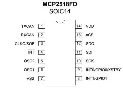
The MCP2518FD is a cost-effective and small-footprint CAN FD controller that can be easily added to a microcontroller with an available SPi interface. The MCP2518FD supports both, CAN frames in the Classical format (CAN2.0B) and CAn Flexible Data Rate (CAN FD) as specified in ISO 11898-1:2015. Its arbitration bit rate is up to 1Mbps, data bit rate up to 8Mbps. It supports up to 29 MHz SPi clock speed. All the standard frame, extended frame, and remote frames are receivable and transmittable. 32 intel flexible filter and mask object allows the CP2518FD to filter usable packets to reduce consumption of MCU.
You can connect this module to your board like Raspberry Pu by SPi interface.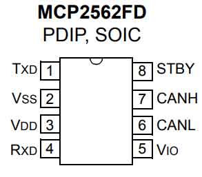
The MCP2561/2FD is a high-speed CAN device,fault-tolerant device that serves as the interface between a CAN protocol controller and the physical bus. The MCP2561/2FD device provides differential transmit and receive capability for the CAN protocol controller, and is fully compatible with the ISO-11898-2 and ISO-11898-5 standards.
The Loop Delay Symmetry is guaranteed to support data rates that are up to 5 Mbps for CAN FD (Flexible Data rate). The maximum propagation delay was improved to support longer bus length. Typically, each node in a CAN system must have a device to convert the digital signals generated by a CAN controller to signals suitable for transmission over the bus cabling (differential output).
Working with Raspberry Pi
The working voltage level of Raspberry Pi is 3.3V, therefore we need to set the VIO of 2-CH CAN FD HAT to 3.3V as below: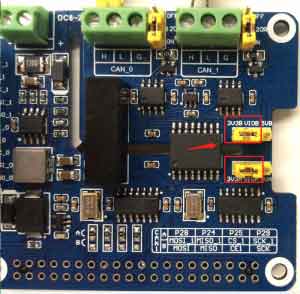
Install libraries
- bcm2835
- Open terminal and run commands below to install bcm2835 library
wget http://www.airspayce.com/mikem/bcm2835/bcm2835-1.60.tar.gz
tar zxvf bcm2835-1.60.tar.gz
cd bcm2835-1.60/
sudo ./configure
sudo make
sudo make check
sudo make install
- Install wiringPi library
sudo apt-get install wiringpi
cd /tmp
wget https://project-downloads.drogon.net/wiringpi-latest.deb
sudo dpkg -i wiringpi-latest.deb
gpio -v
- Install python library
python2
sudo apt-get update
sudo apt-get install python-pip
sudo apt-get install python-pil
sudo apt-get install python-numpy
sudo pip install RPi.GPIO
sudo pip install spidev
sudo pip2 install python-can
python3
sudo apt-get update
sudo apt-get install python3-pip
sudo apt-get install python3-pil
sudo apt-get install python3-numpy
sudo pip3 install RPi.GPIO
sudo pip3 install spidev
sudo pip3 install python-can
Download demo codes
The demo codes can be found and downloaded on #Resource part.
Download and unzip it.
Copy demo to the home(~) directory of Raspberry Pi.
Install driver
- 1. Enter the directory of driver
cd ~/2-CH-CAN-FD-HAT-Demo/Raspberry_Pi/
sudo chmod -R 777 Linux_Driver/
cd Linux_Driver/
ls

sudo ./install.sh
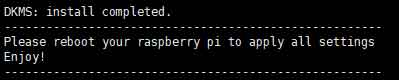
- 3.Reboot and check
- After installing, reboot your Raspberry Pi and check if the driver is installed properly.
sudo reboot
dmesg | grep spi
- A work mode should be
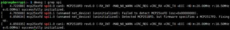
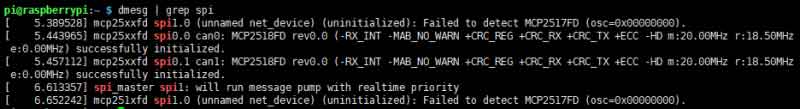
【Note1】Mode A is factory default, and mode B CAN be realized by changing the resistance. In mode A, two CAN channels use two sets of independent SPI respectively, while in mode B, two CAN channels share one set of SPI. See the figure below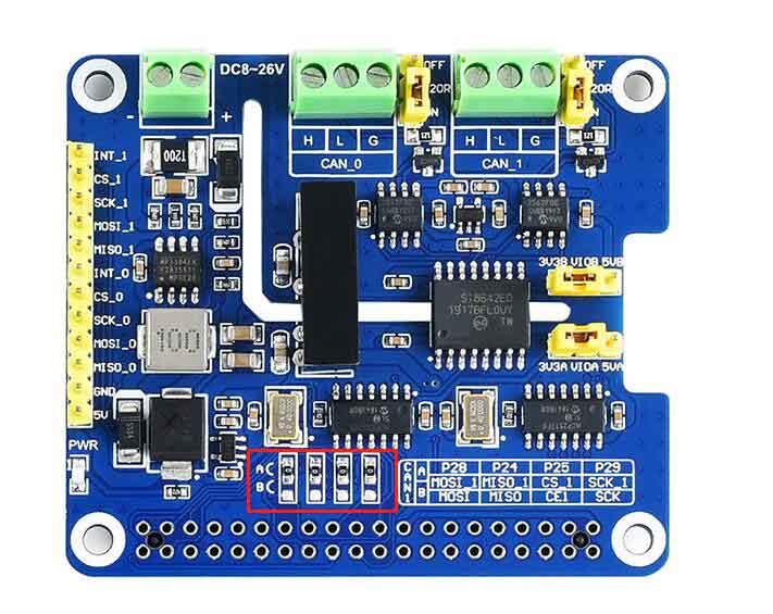
【Note2】Because the compatible detection method is adopted, there will be additional information during the initialization, which does not affect the normal use and can be ignored
Set buad rate
You can set the baud rate, working mode, and buffer size.
sudo ip link set can1 up type can bitrate 1000000 dbitrate 8000000 restart-ms 1000 berr-reporting on fd on
sudo ifconfig can0 txqueuelen 65536
sudo ifconfig can1 txqueuelen 65536
The available modes:
- [ loopback { on | off } ]
- [ listen-only { on | off } ]
- [ triple-sampling { on | off } ]
- [ one-shot { on | off } ]
- [ berr-reporting { on | off } ]
The FD type:
- [ fd { on | off } ]
- [ fd-non-iso { on | off } ]
For more details of CAN commands, please refer to : https://www.kernel.org/doc/Documentation/networking/can.txt
Check the can bus:
ifconfig

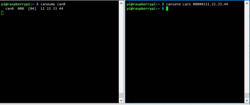
Testing
If you have only one 2-CH CAN FD HAT, you can connect CAN0_H to CAN1_H, and CAN0_L to CAN0_L to CAN1_L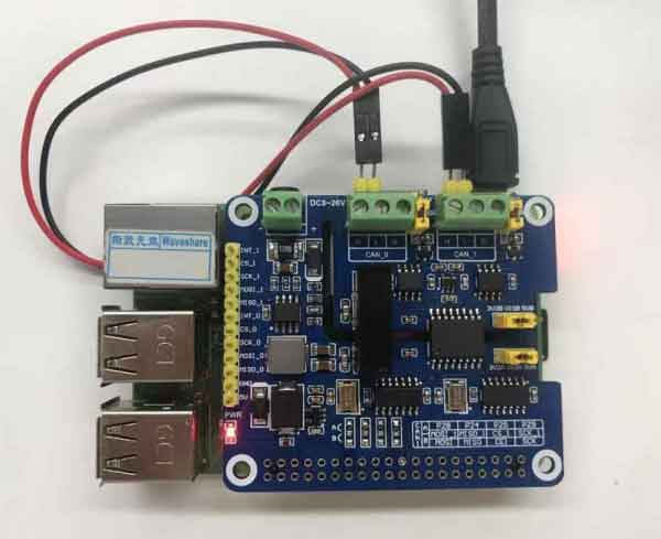
Open two terminals, one works are sender and another is receiver.
receiver:
candump can0
sender:
cansend can1 000##11.22.33.44
Python example
- 1. Enter the direcory of python example
cd 2-CH CAN FD HAT/Raspberry Pi/python
- 2. Run the receiver.py script in receiver terminal
sudo python receive.py
- 3. Run the send.py script in sender terminal
sudo python send.py
【Note】 The CAN1 is used as sender, and CAN0 is used as receiver.
Codes analysis
The demo codes provided is based on python, please check that if you installed the python-can library.
- 1. Before you send data, you should create a CAN device firstly,
os.system('sudo ip link set can0 up type can bitrate 1000000 dbitrate 8000000 restart-ms 1000 berr-reporting on fd on')
This code is used to initialize CAN0 as receiver/sender. If you want to change it to CNA1, you can use this one:
os.system('sudo ip link set can1 up type can bitrate 1000000 dbitrate 8000000 restart-ms 1000 berr-reporting on fd on')
- 2. Connect to CAN BUS
can0 = can.interface.Bus(channel = 'can0', bustype = 'socketcan_ctypes')# socketcan_native
or
can1 = can.interface.Bus(channel = 'can1', bustype = 'socketcan_ctypes')# socketcan_native
- 3. Create message
msg = can.Message(arbitration_id=0x123, data=[0, 1, 2, 3, 4, 5, 6, 7], extended_id=False)
- 4. Send message
can0.send(msg)
or
can1.send(msg)
- 5. Finally, close CAN device
os.system('sudo ifconfig can0 down')
or
os.system('sudo ifconfig can1 down')
- Receive message
msg = can0.recv(10.0)
The variables of recv() function is the timeout of receving.
For more information, please refer to https://python-can.readthedocs.io/en/stable/interfaces/socketcan.html
Arduino example
The example of Arduino is based on the MCP2518FD project of Pierre Molinaro (Thanks to Pierre Molinaro).
To run the example, you should prepare two Arduino boards and two 2-CH CAN FD HAT. Note that the working level of most of Arduino board is 5V, therefore we should set the VIO to 5V as below: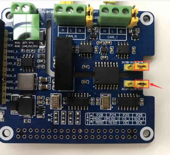
Connection
| PIN | Arduino UNO |
| 5V | 5V |
| GND | GND |
| MISO_O | D12(MISO) |
| MOSI_0 | D11(MOSI) |
| SCK_0 | D13(SCK) |
| CS_0 | D10 |
| INT_0 | D2 |
Connect CAN0_H and CAN0-L of one HAT to another's. Set the baudrate of Serial monitor to 115200 and check the data: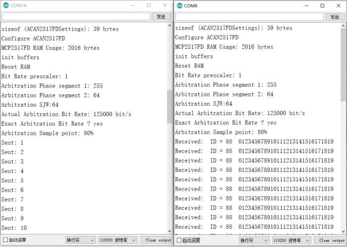
