


- sales/support
Google Chat:---
- sales
+86-0755-88291180
- sales01
sales@spotpear.com
- sales02
dragon_manager@163.com
- support
tech-support@spotpear.com
- CEO-Complaints
zhoujie@spotpear.com
- Only Tech-Support
WhatsApp:13246739196
- Purchase/Shipping/Refund
WhatsApp:13424403025
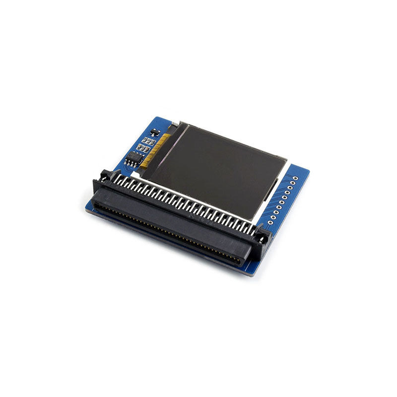
1.8inch LCD for micro:bit User Guide
Introduction
This is a colorful display module designed for the BBC micro:bit, 1.8inch diagonal, 160x128 pixels, capable of displaying 65K colors.
Tired of the 5x5 LED matrix? Time to get a tiny monitor for your micro:bit, this one would be the ideal choice.
Specification
- Driver: ST7735S
- Resolution: 160x128
- Display color: RGB, 65K colors
- Operating voltage: 3.3V
- Dimension: 61mm x 51.5mm
Pinouts
| PIN | micro:bit PIN | Description |
|---|---|---|
| Vcc | 3V3 | Power |
| GND | GND | Ground |
| MISO | P14 | SPI data master input/slave output |
| MOSI | P15 | SPI data master output/slave input |
| SCK | P13 | SPI clock input |
| LCD_CS | P16 | LCD chip selection |
| RAM_CS | P2 | SRAM chip selection |
| DC | P12 | LCD data/command |
| RST | P8 | LCD reset |
| BL | P1 | LCD backlight |
Programming Guide
Micor:bit has variety of programming methods like mbed, micropython, typescript and other programming methods, as well as code online websites which are abundant.
The official recommendation are two programming methods: typescript and micropython. Typescript is the graphical programming language.
Note:For this LCD, we only provide demo code of typescript
Typescript
Typescript is a kind of graphical programming, its website is that: https://makecode.microbit.org/#
- Open a browser and input the next URL
- Create a new empty project
Click Project->New Project to create an empty project. Rename the project as LCD or any one you like to.
- Add Packeage
You can get the package of 1.8inch LCD for micro;bit from github. Click More..->Add Package, then copy the URL to the Edittext. https://github.com/waveshare/WSLCD1in8
Note: add a space follow the address
The Blocks
- Initiation
You need to initial LCD module first.
- Clear the screen
Clear the screen to white. Create an buffer on RAM with the resolution size 160*128 and initial it to white.
- Set the backlight

- Send display data
With this block, it will send one frame of buffer to the LCD and display. Note: it is always following drawing operation
- Draw point

Place the block before send display data. You can choose the position, color and size. For the screen, (1,1) is on top-left, and (160,128) is on bottom-right
There are tow way to set the color, the one is use the color block as above, another is to set the value (RGB565) by drag the slider.
- Draw line
You can choose the the line's position, color, size and its sytle
solid line:
dotted line: just need to change the Style
- Draw frame
Draw empty rectange:

Draw full rectange:
- Draw circle
Draw empty circle:
Draw full circle:
- Draw string

- Partial refresh
You can set display windows and refresh it on LCD instead of full refresh
Initialize LCD, set the backlight and then draw a rectangle from (30, 30) to (80, 80)
Then set the display windows block and set its position