- sales/support
Google Chat:---
- sales
+86-0755-88291180
- sales01
sales@spotpear.com
- sales02
dragon_manager@163.com
- support
tech-support@spotpear.com
- CEO-Complaints
zhoujie@spotpear.com
- Only Tech-Support
WhatsApp:13246739196
- Purchase/Shipping/Refund
WhatsApp:13424403025
- HOME
- >
- ARTICLES
- >
- Common Moudle
- >
- ESP
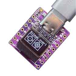
ESP32 C3 0.42LCD gif_01 Graphics Test
1、 Create a project folder
2、 Open the arduino IDE
3、 Select Chip
3.1. Click on tools
3.2. Click on board
3.3. Click on esp32 and select esp32-c3
4、 Configure required files
4.1Save, save the file in the folder you created
4.2Place this (sprial_72x40. h file link) file in the folder of the engineering project.

5、Burn Code
#include<Wire.h>
#include<OneBitDisplay.h>
#include<AnimatedGIF.h>
// Compile the GIF file animation into FLASH with the code
#include"spiral_72x40.h"
ONE_BIT_DISPLAY obd;
AnimatedGIF gif;
staticuint8_t*pBuffer;// holds current frame for OLED
#defineDISPLAY_WIDTH72
#defineDISPLAY_HEIGHT40
#ifdefARDUINO_ARCH_MBED
#defineSDA_PIN22
#defineSCL_PIN23
externMbedI2C *pWire;
#else
externTwoWire *pWire;
#defineSDA_PIN5
#defineSCL_PIN6
#endif
voidDrawPixel(intx,inty,uint8_tucColor)
{
uint8_tucMask;
intindex;
if(x >= DISPLAY_WIDTH || y >= DISPLAY_HEIGHT)
return;
ucMask =1<<(y &7);
index = x +((y >>3)* DISPLAY_WIDTH);
if(ucColor)
pBuffer[index] |= ucMask;// set the pixel (white)
else
pBuffer[index] &= ~ucMask;// clear the pixel (black)
}
//
// Called once per scanline as the GIF is decoded
//
voidGIFDraw(GIFDRAW*pDraw)
{
uint8_t*s;
intx, y, iWidth;
staticuint8_tucPalette[256];// thresholded palette
if(pDraw->y==0)// first line, convert palette to 0/1
{
for(x =0; x <256; x++)
{
uint16_tusColor =pDraw->pPalette[x];
intgray =(usColor & 0xf800)>>8;// red
gray +=((usColor & 0x7e0)>>2);// plus green*2
gray +=((usColor & 0x1f)<<3);// plus blue
ucPalette[x] =(gray >>9);// 0->511 = 0, 512->1023 = 1
}
}
y =pDraw->iY+pDraw->y;// current line
iWidth =pDraw->iWidth;
if(iWidth > DISPLAY_WIDTH)
iWidth = DISPLAY_WIDTH;
s =pDraw->pPixels;
if(pDraw->ucDisposalMethod==2)// restore to background color
{
for(x=0; x<iWidth; x++)
{
if(s[x] ==pDraw->ucTransparent)
s[x] =pDraw->ucBackground;
}
pDraw->ucHasTransparency=0;
}
// Apply the new pixels to the main image
if(pDraw->ucHasTransparency)// if transparency used
{
uint8_tc, ucTransparent =pDraw->ucTransparent;
intx;
for(x=0; x < iWidth; x++)
{
c = *s++;
if(c != ucTransparent)
DrawPixel(pDraw->iX+ x, y,ucPalette[c]);
}
}
else
{
s =pDraw->pPixels;
// Translate the 8-bit pixels through the RGB565 palette (already byte reversed)
for(x=0; x<pDraw->iWidth; x++)
DrawPixel(pDraw->iX+ x, y,ucPalette[*s++]);
}
if(pDraw->y==pDraw->iHeight-1)// last line, render it to the display
obd.display();
}/* GIFDraw() */
voidsetup(){
obd.setI2CPins(SDA_PIN, SCL_PIN);
obd.I2Cbegin(OLED_72x40);
obd.allocBuffer();
pBuffer =(uint8_t*)obd.getBuffer();
obd.fillScreen(0);
obd.setFont(FONT_8x8);
//obd.setContrast(40);
obd.print("GIF Demo");
obd.display();
delay(2000);
gif.begin(LITTLE_ENDIAN_PIXELS);
}/* setup() */
voidloop(){
// Loop continuously over the animated sequence
if(gif.open((uint8_t*)spiral_72x40, sizeof(spiral_72x40), GIFDraw))// play the GIF from FLASH storage
{
// Serial.printf("Successfully opened GIF; Canvas size = %d x %d\n", gif.getCanvasWidth(), gif.getCanvasHeight());
while(gif.playFrame(false,NULL))
{
}
gif.close();
}
}/* loop() */
6.1. Copy the code into the Arduino IDE
6.2. Use a type-c cable to connect the computer to the ESP 32-c3 development board. After successful connection, the serial port will be displayed in the computer management window
6.3Click on Tools in the Arduino IDE, then click on Port and select the serial port Adafruit QT ESP32-C3
6.4Click on Verify
6.5.Click on upload
6.6.The test results are as follows