


- sales/support
Google Chat:---
- sales
+86-0755-88291180
- sales01
sales@spotpear.com
- sales02
dragon_manager@163.com
- support
tech-support@spotpear.com
- CEO-Complaints
zhoujie@spotpear.com
- Only Tech-Support
WhatsApp:13246739196
- Purchase/Shipping/Refund
WhatsApp:13424403025
- HOME
- >
- ARTICLES
- >
- Common Moudle
- >
- Power
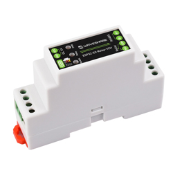
ESP32-S3-Relay-1CH User Guide
Introduction
Introduction
ESP32-S3-Relay-1CH is an industrial-grade 1-channel WiFi network relay based on ESP32-S3 main controller and supports WiFi, Bluetooth, RS485, and other peripheral interfaces. It has built-in protection circuits such as power supply isolation and optodecoupler isolation, which is safe, stable and reliable, and suitable for the AIoT field.
Features
- Based on ESP32-S3 microcontroller with Xtensa 32-bit LX7 dual-core processor with frequency up to 240MHz
- Integrated 2.4GHz WiFi and Bluetooth 5 (LE) dual-mode wireless communication, with superior RF performance
- High quality relay, contact rating: ≤10A 250V AC or ≤10A 30V DC
- Onboard isolated RS485 interface, for connecting to various RS485 Modbus industrial modules or sensors
- Onboard RTC clock chip, supports timing tasks
- Onboard USB Type-C port for power supply, firmware downloading and debugging, making development more convenient
- Onboard power supply screw terminal, supports 5V power supply only
- Onboard optocoupler isolation to prevent interference with control chip from external high-voltage circuit connected to the relay
- Onboard digital isolation to avoid external signal interference with the control chip
- Onboard integrated power isolation, providing stable isolation voltage, no extra power supply required for the isolated terminal
- Onboard RS485 TX/RX indicators for monitoring the operating status of the module
- Rail-mounted protective enclosure, easy to install, safe to use
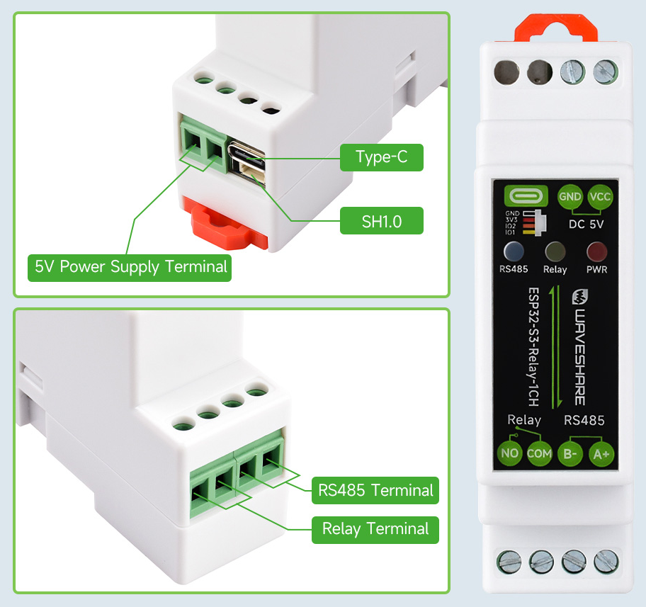
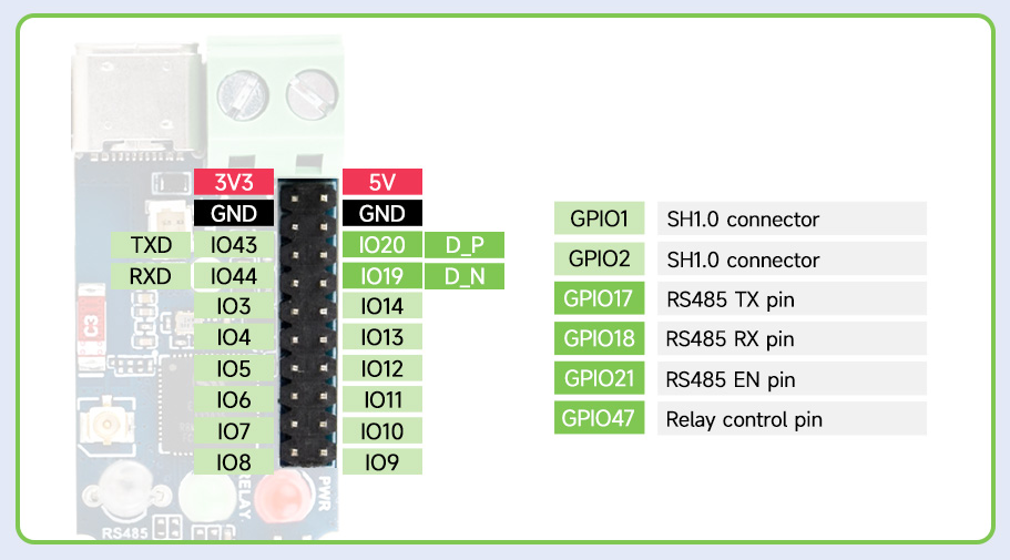
Interfaces
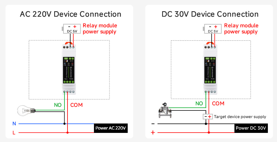
Schematic Diagram of Device Wiring
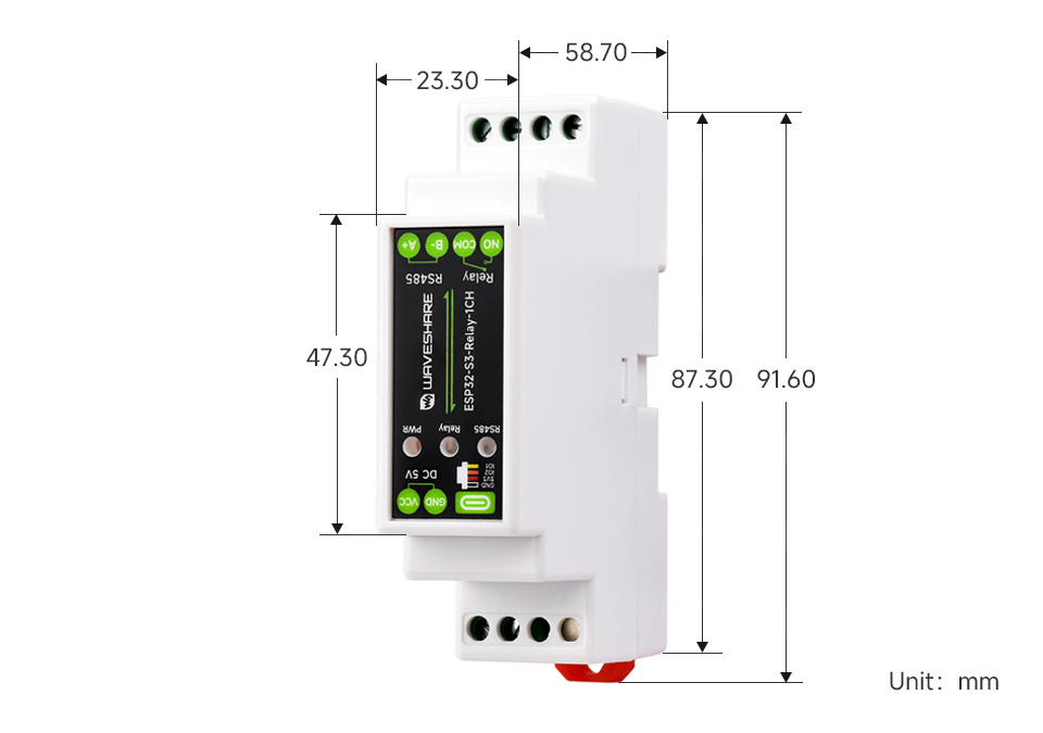
Dimensions
Electrical Safety Precautions
- This product should be operated and used by professional electricians or technical personnel. During use, please ensure electrical safety and take protective measures such as anti-leakage and insulation.
- Before installing, maintaining, or replacing relay device, make sure to turn off the power and unplug the device.
- Do not attempt to dismantle relay device to avoid damaging the device or risking electric shock.
- Please properly install and place the relay device. Avoid using it in damp, overly hot, or flammable environments to prevent safety accidents due to improper installation or use.
Usage Guide
ESP32-S3-Relay-1CH currently provides Arduino-IDF development tool and framework, and you can choose the right development tool according to your project needs and personal habits.
Development Tool
| Arduino IDEArduino IDE is an open source electronic prototyping platform, convenient and flexible, easy to get started. After a simple learning, you can start to develop quickly. At the same time, Arduino has a large global user community, providing an abundance of open source code, project examples and tutorials, as well as rich library resources, encapsulating complex functions, allowing developers to quickly implement various functions. |
Components Preparation
- ESP32-S3-Relay-1CH x1
- USB cable (Type-A male to Type-C male) x1
- Modbus RTU Relay x 1
- USB TO RS232/485 x 1
Working with Arduino
This chapter introduces setting up the Arduino environment, including the Arduino IDE, management of ESP32 boards, installation of related libraries, program compilation and downloading, as well as testing demos. It aims to help users master the development board and facilitate secondary development.
Environment Setup
Download and Install Arduino IDE
- Click to visit the Arduino official website, select the corresponding system and system bit to download
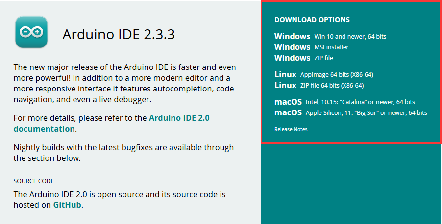
- Run the installer and install all by default
Install ESP32 Development Board
- Regarding ESP32-related motherboards used with the Arduino IDE, the 'esp32 by Espressif Systems library must be installed first.
- According to Board installation requirement, it is generally recommended to use Install Online. If online installation fails, use Install Offline
- For the installation tutorial, please refer to Arduino board manager tutorial
| Board name | Board installation requirement | Version number requirement |
|---|---|---|
| esp32 by Espressif Systems | "Install Offline" / "Install Online" | 3.0.x |
Install Library
- When installing Arduino libraries, there are usually two ways to choose from: Install online and Install offline. If the library installation requires offline installation, you must use the provided library file
For most libraries, users can easily search and install them through the online library manager of the Arduino software. However, some open-source libraries or custom libraries are not synchronized to the Arduino Library Manager, so they cannot be acquired through online searches. In this case, users can only manually install these libraries offline. - For library installation tutorial, please refer to Arduino library manager tutorial
- ESP32-S3-Relay-1CH library file is stored in the demo, click here to jump: ESP32-S3-Relay-1CH Demo
| Library Name | Description | Version | Library Installation Requirement |
|---|---|---|---|
| ArduinoJson | Lightweight JSON library | v6.21.4 | "Install Online" or "Install Offline" |
| PubSubClient | MQTT message subscription publishing library | v2.8.0 | "Install Online" or "Install Offline" |
| NTPClient | Network time synchronization client library | v3.2.1 | "Install Online" or "Install Offline" |
Run the First Arduino Demo
New Project
- Run the Arduino IDE and select
File->New Sketch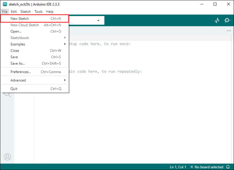
- Enter the code:
void setup() {
  // put your setup code here, to run once:
  Serial.begin(115200);
}

void loop() {
  // put your main code here, to run repeatedly:
  Serial.println("Hello, World!");
  delay(2000);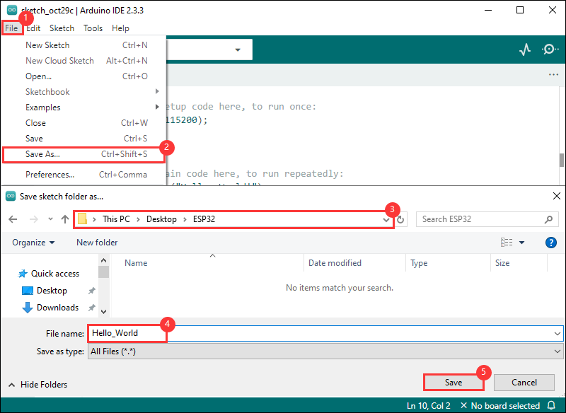
}- Save the project and select
File->Save As.... In the pop-up menu, select the path to save the project, and enter a project name, such as Hello_World, clickSave
Compile and Flash Demos
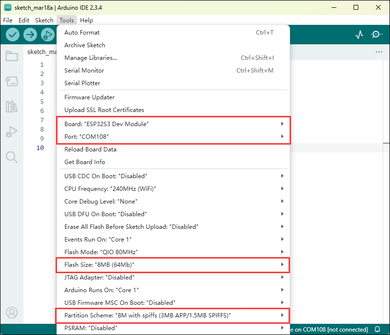
- Select the corresponding development board, take the ESP32S3 motherboard as an example:
①. Click to select the dropdown menu option Select Other Board and Port;
②. Search for the required development board model esp32s3 dev module and select;
③. Select COM Port;
④. Save the selection.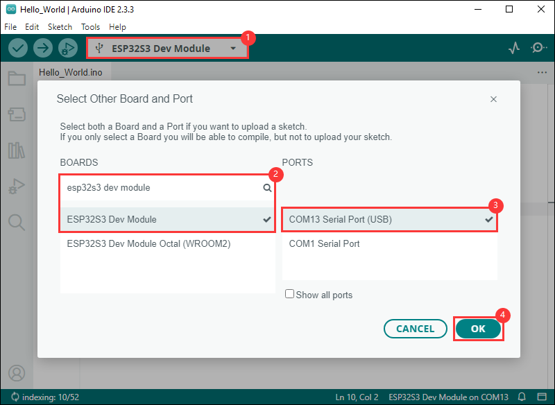
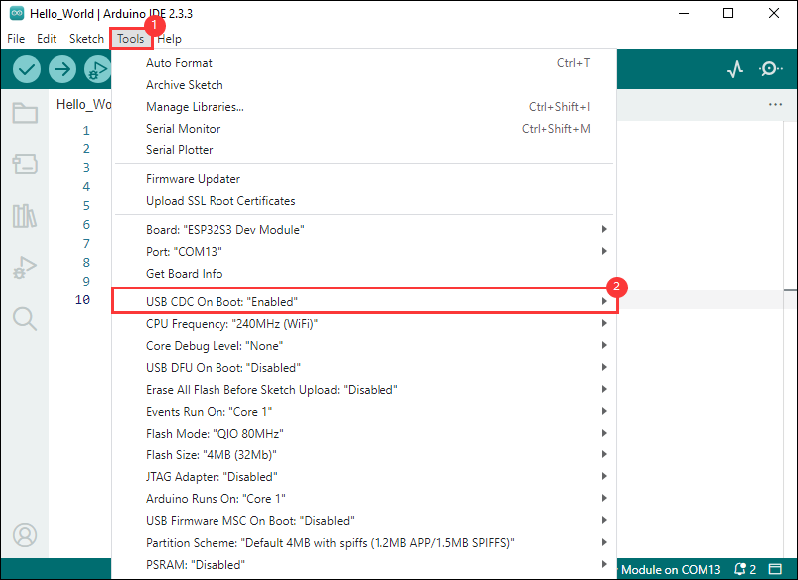
- If the ESP32S3 mainboard only has a USB port, you need to enable USB CDC, as shown in the following diagram:
- Compile and upload the program:
①. Compile the program; ②. Compile and download the program; ③. Download successful.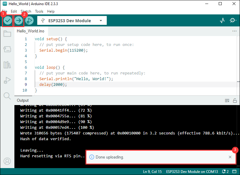
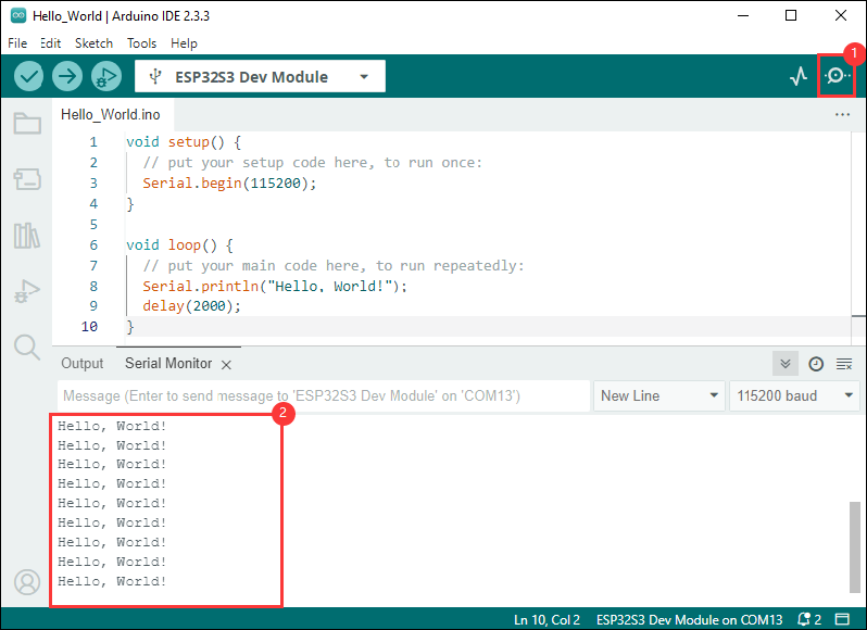
- Open the Serial Monitor window, and the demo will print "Hello World!" every 2 seconds, and the operation is as follows:
Demo

| Demo | Basic Description | Dependency Library |
|---|---|---|
| 01_MAIN_WIFI_AP | RS485 interface control, Bluetooth control, Bluetooth send IP, Web page control (short distance) | Can be flashed directly Web pages are only available if they are connected to device WIFI |
| 02_MAIN_WIFI_STA | RS485 interface control, Bluetooth control, Bluetooth send IP, Web page control (short distance) | Need to modify the WIFI to be connected Web pages can only be used within the intranet |
| 03_MAIN_WIFI_MQTT | RS485 interface control, Bluetooth control, Bluetooth transmit IP, Waveshare cloud control (long distance) | Need to modify the WIFI to be connected The device must be created in the Waveshare cloud |
| 04_MAIN_ALL | RS485 interface control, Bluetooth control, Bluetooth send IP, Web page control (short distance), Waveshare cloud control (long distance) | Need to modify the WIFI to be connected The device must be created in the Waveshare cloud Web pages can only be used within the intranet |
Arduino Project Parameter Setting
01_MAIN_WIFI_AP
Demo description
- This demo implements the control of 1 relay switch through WiFi, Bluetooth, and RS485. The AP mode of WiFi is enabled in this demo
Precautions
- Can be flashed directly
- Web pages are only available if they are connected to device WIFI
02_MAIN_WIFI_STA
Demo description
- This example implements the control of six relay switches through WiFi, Bluetooth, and RS485. The STA mode of WiFi is enabled in this example
Precautions
- Need to modify the WIFI to be connected
- The Web page only supports controlling the device and this product to be used under the same network, if you use the mobile phone control, you need to turn off the mobile network
03_MAIN_WIFI_MQTT
Demo description
- This example controls 6 relays through MQTT, Bluetooth, and RS485 communication methods. It uses ESP32 as the main control unit, supports Wi-Fi and Bluetooth connections, and provides remote control based on the MQTT protocol
Precautions
- Need to modify the WIFI to be connected
- Must create the device in Waveshare Cloud
04_MAIN_ALL
Demo description
- This example is a collection of RS485 interface control, Bluetooth control, Web page control (near distance), and Waveshare cloud control (long distance).
Precautions
- Need to modify the WIFI to be connected
- The Web page only supports controlling the device and this product to be used under the same network, if you use the mobile phone control, you need to turn off the mobile network
- Must create the device in Waveshare Cloud
External Expansions
RS485 Extended Relay Channels
- Use Modbus RTU Relay to extend 8-ch relay
- The 4 main example files are compatible with this operation, and the Extension_Enable in WS_imformification. h needs to be set to 1 (default is 1)
- Externally extended relays can be controlled via Bluetooth
Operation Command Command Function 06 01 Switch the CH1 relay status of Modbus RTU Relay 06 02 Switch the CH2 relay status of Modbus RTU Relay 06 03 Switch the CH3 relay status of Modbus RTU Relay 06 04 Switch the CH4 relay status of Modbus RTU Relay 06 05 Switch the CH5 relay status of Modbus RTU Relay 06 06 Switch the CH6 relay status of Modbus RTU Relay 06 07 Switch the CH7 relay status of Modbus RTU Relay 06 08 Switch the CH8 relay status of Modbus RTU Relay 06 09 Turn on all relays of Modbus RTU Relay 06 0A Turn off all relays of Modbus RTU Relay
- The commands for Bluetooth control relay are characters 1-8, which are hexadecimal 0x06 0x01 ~ 0x38 0x0A
- Click the SEND button and fill in the data to be sent (currently hexadecimal sending), enter 0x06 0x01 as below
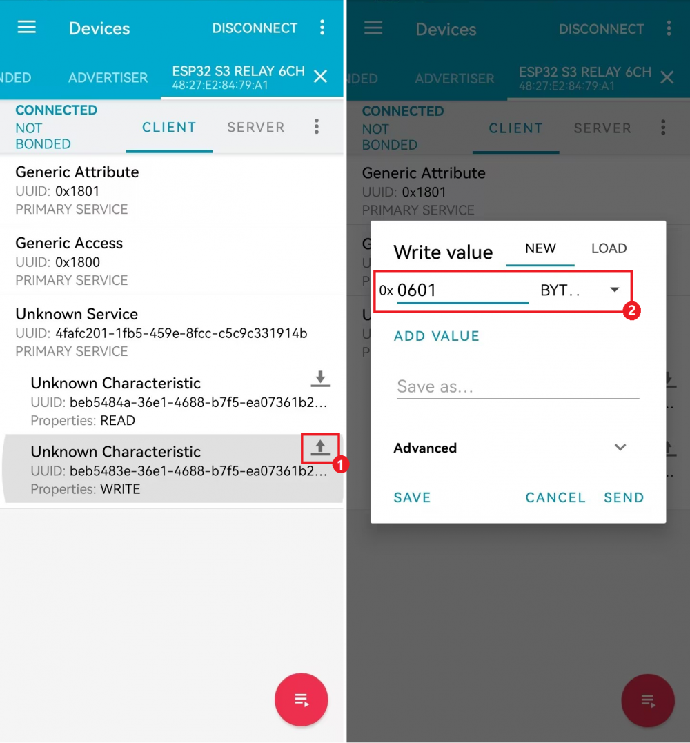
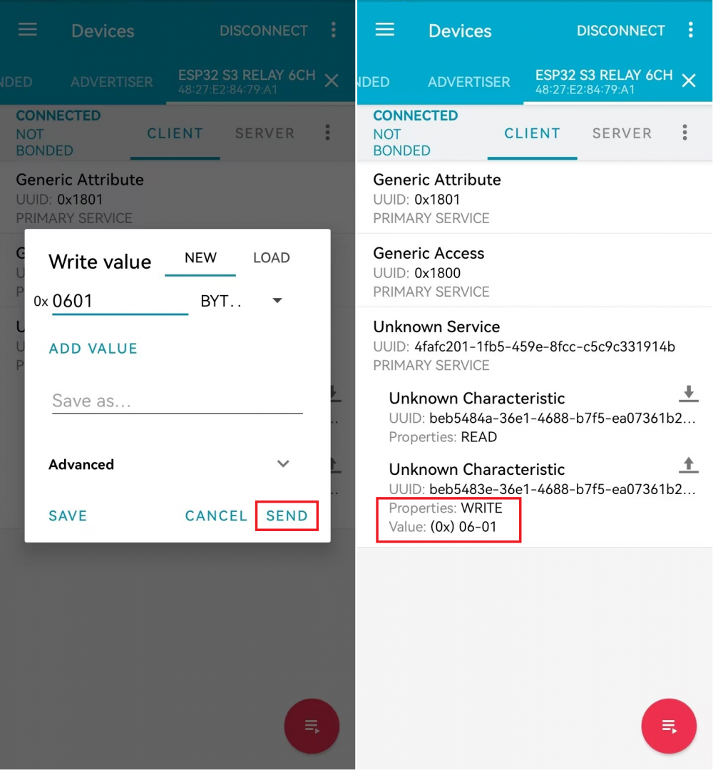
- Send 0x06 0x01 to control relay CH1 for status reversal
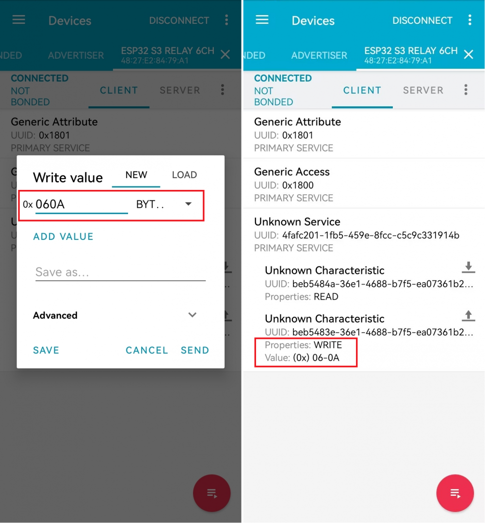
- Send 0x06 0x0A to control to turn off all relays
Flash Firmware Flashing and Erasing
- The current demo provides test firmware, which can be used to test whether the onboard device functions properly by directly flashing the test firmware
- bin file path:
..\ESP32-S3-Relay-1CH\Firmware\Factory bin
Working with Homeassistant
The product can be controlled online through the Homeassistant built on the Raspberry Pi, and the relevant operations can be found in Reference link
Resources
Demo
Datasheets
ESP32-S3
Software Tools
Arduino
VScode
Thonny
Debugging Tools
Other Resource Links
FAQ
Question: After the module downloads the demo and re-downloads it, why sometimes it can't connect to the serial port or the flashing fails?
- Long press the BOOT button, press RESET at the same time, then release RESET, then release the BOOT button, at this time the module can enter the download mode, which can solve most of the problems that can not be downloaded.
Question: Why does the module keep resetting and flicker when viewed the recognition status from the device manager?
- It may be due to Flash blank and the USB port is not stable, you can long-press the BOOT button, press RESET at the same time, and then release RESET, and then release the BOOT button, at this time the module can enter the download mode to flash the firmware (demo) to solve the situation.
Question: How to deal with the first compilation of the program being extremely slow?
- It's normal for the first compilation to be slow, just be patient
Question: How to handle the display "waiting for download..." on the serial port after successfully ESP-IDF flashing?
- If there is a reset button on the development board, press the reset button; if there is no reset button, please power it on again
Question: What should I do if I can't find the AppData folder?
- Some AppData folders are hidden by default and can be set to show.
- English system: Explorer->View->Check "Hidden items"
- Chinese system: File Explorer -> View -> Display -> Check "Hidden Items"
Question: How do I check the COM port I use?
- Windows system:
①View through Device Manager: Press the Windows + R keys to open the "Run" dialog box; input devmgmt.msc and press Enter to open the Device Manager; expand the "Ports (COM and LPT)" section, where all COM ports and their current statuses will be listed.
②Use the command prompt to view: Open the Command Prompt (CMD), enter the "mode" command, which will display status information for all COM ports.
③Check hardware connections: If you have already connected external devices to the COM port, the device usually occupies a port number, which can be determined by checking the connected hardware.
- Linux system:
①Use the dmesg command to view: Open the terminal.
①Use the ls command to view: Enter ls /dev/ttyS* or ls /dev/ttyUSB* to list all serial port devices.
③Use the setserial command to view: Enter setserial -g /dev/ttyS* to view the configuration information of all serial port devices.
Question: Why does the program flashing fail when using a MAC device?
- Install MAC Driver and flash again.
Question: Why is there no output after successfully flashing the code with no issues?
- Check the schematic diagram for different development boards with Type-C interfaces, and handle the output accordingly:
- For development boards with direct USB output, printf function is supported for printing output. If you want to support output via the Serial function, you will need to enable the USB CDC On Boot feature or declare HWCDC.
- For development boards with UART to USB conversion, both printf and Serial functions are supported for printing output, and there is no need to enable USB CDC On Boot.
Question: Please note!
- The factory demo is for learning only, if it is used for practical application, please optimize the demo logic by yourself.
Question: When controlling other devices using RS485, it is not sensitive or communication fails?
- Please move the jumper cap to 120R and try again. Some RS485 devices require a 120R resistor to be connected in series
Support
Monday-Friday (9:30-6:30) Saturday (9:30-5:30)
Email: services01@spotpear.com
[Tutorial Navigation]
- Introduction
- Electrical Safety Precautions
- Usage Guide
- Working with Arduino
- External Expansions
- Flash Firmware Flashing and Erasing
- Working with Homeassistant
- Resources
- FAQ
- Question: After the module downloads the demo and re-downloads it, why sometimes it can't connect to the serial port or the flashing fails?
- Question: Why does the module keep resetting and flicker when viewed the recognition status from the device manager?
- Question: How to deal with the first compilation of the program being extremely slow?
- Question: How to handle the display "waiting for download..." on the serial port after successfully ESP-IDF flashing?
- Question: What should I do if I can't find the AppData folder?
- Question: How do I check the COM port I use?
- Question: Why does the program flashing fail when using a MAC device?
- Question: Why is there no output after successfully flashing the code with no issues?
- Question: Please note!
- Question: When controlling other devices using RS485, it is not sensitive or communication fails?
- Support