- sales/support
Google Chat:---
- sales
+86-0755-88291180
- sales01
sales@spotpear.com
- sales02
dragon_manager@163.com
- support
tech-support@spotpear.com
- CEO-Complaints
zhoujie@spotpear.com
- sales/support
WhatsApp:13246739196
- HOME
- >
- ARTICLES
- >
- Common Moudle
- >
- ESP
ESP32-S3-GEEK Guide
Overview
Introduction
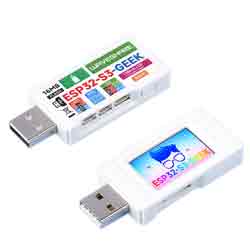
ESP32-S3-GEEK is a geek development board designed by Waveshare, onboard USB-A port, 1.14inch LCD screen, a TF card slot, and other peripherals. Supports 2.4GHz WiFi and BLE 5, with integrated 16MB Flash & 2MB PSRAM, provides I2C port, UART port, and GPIO header, bringing more possibilities for your project.
Features
- Adopts ESP32-S3R2 chip with Xtensa® 32-bit LX7 dual-core processor, capable of running at 240 MHz.
- Built-in 512KB SRAM, 384KB ROM, 2MB of on-chip PSRAM, and onboard 16MB Flash memory.
- Onboard 1.14inch 240×135 pixels 65K color IPS LCD display.
- Integrated 2.4GHz WiFi and Bluetooth 5 (LE) wireless communication.
- WiFi supports Infrastructure BSS in Station, SoftAP, and Station + SoftAP modes.
- WiFi supports 1T1R mode with a data rate of up to 150 Mbps.
- Bluetooth supports high power mode (20dBm).
- Internal co-existence mechanism between Wi-Fi and Bluetooth to share the same antenna.
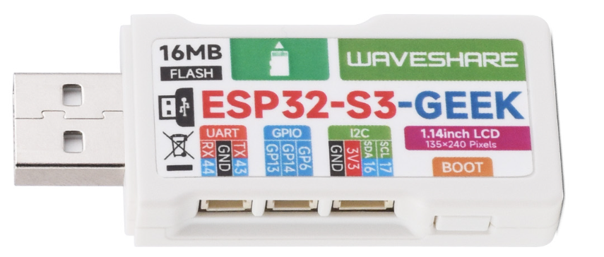
- The onboard 3-pin UART interface can function as a USB-to-serial adapter.
- The onboard 3-pin GPIO interface can be used for debugging other modules or for ADC data collection.
- The onboard 4-pin I2C interface is available for testing the target board.
- Equipped with plastic case and cables.
- Provides online open-source demos and resources, more convenient for learning and development.
Onboard Resources
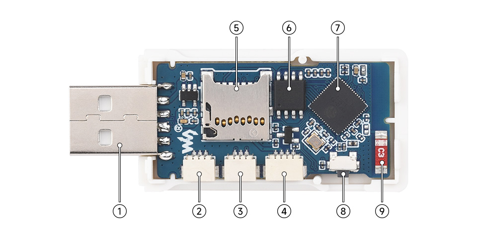
1.USB-A Interface 2.UART Interface 3.GPIO Interface 4.I2C Interface 5.TF Card Slot | 6.W25Q128JVSIQ 7.ESP32-S3 8.BOOT Button 9.Antenna |
Interfaces
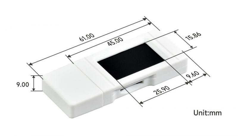
Dimensions
Usage instructions
ESP32-S3-GEEK currently provides two development tools and frameworks, Arduino IDE , ESP-IDF and MicroPython, providing flexible development options, you can choose the right development tool according to your project needs and personal habits.
Development tools
| Arduino IDEArduino IDE is an open source electronic prototyping platform, convenient and flexible, easy to get started. After a simple learning, you can start to develop quickly. At the same time, Arduino has a large global user community, providing an abundance of open source code, project examples and tutorials, as well as rich library resources, encapsulating complex functions, allowing developers to quickly implement various functions. |
| MicroPythonMicropython is a full implementation of the Python 3 programming language that runs directly on embedded hardware such as ESP32, Raspberry Pi Pico, etc. You can run Python scripts directly on the board through REPL, which is very suitable for rapid prototyping. |
| ESP-IDFESP-IDF, or full name Espressif IDE, is a professional development framework introduced by Espressif Technology for the ESP series chips. It is developed using the C language, including a compiler, debugger, and flashing tools, etc., and can be developed via the command lines or through an integrated development environment (such as Visual Studio Code with the Espressif IDF plugin). The plugin offers features such as code navigation, project management, and debugging. |
Each of these two development approaches has its own advantages, and developers can choose according to their needs and skill levels. Arduino and MicroPython are suitable for beginners and non-professionals because they are easy to learn and quick to get started. ESP-IDF is a better choice for developers with a professional background or high performance requirements, as it provides more advanced development tools and greater control capabilities for the development of complex projects.
Components preparation
- ESP32-S3-GEEK x1
- TF card x1
- BME680 Environmental Sensor x1
- USB to UART Universal Serial Communication Module x1

Precautions
- The development board uses USB to download programs. If the port cannot be recognized, please enter boot mode (press the boot button, connect to the computer, and then release the boot button). After downloading the program, disconnect the device and reconnect it to the computer to run the program
Working with Arduino
This chapter introduces setting up the Arduino environment, including the Arduino IDE, management of ESP32 boards, installation of related libraries, program compilation and downloading, as well as testing demos. It aims to help users master the development board and facilitate secondary development.
Environment setup
Download and install Arduino IDE
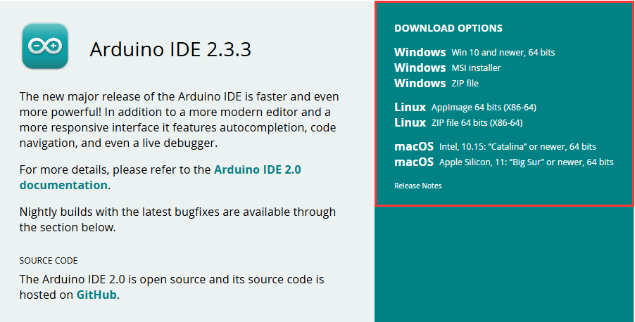
- Click to visit the official website, select the corresponding system and system bit to download.The version of Arduino IDE needs to be 1.8 or higher, and the installation path must not contain Chinese characters, otherwise errors will occur during compilation.
- Run the installer and install all by default.
Install ESP32 Development Board
- Regarding ESP32-related motherboards used with the Arduino IDE, the esp32 by Espressif Systems development board software package must be installed first.
- Install according to the board installation requirements.It is generally recommended to use Install Online. If online installation fails, use Install Offline.
- For installation instructions,please refer to Arduino board manager tutorial
- The esp32 by Espressif Systems development board comes with an offline software. Click here to download: esp32_package_2.0.7_arduino offline package
| Board name | Board installation requirements | Version number requirements |
|---|---|---|
| esp32 by Espressif Systems | "Install Offline" / "Install Online" | 2.0.7 |
Install library
- When installing Arduino libraries, there are usually two ways to choose from: Install online and Install offline. If the library installation requires offline installation, you must use the provided library file
For most libraries, users can easily search and install them through the online library manager of the Arduino software. However, some open-source libraries or custom libraries are not synchronized to the Arduino Library Manager, so they cannot be acquired through online searches. In this case, users can only manually install these libraries offline. - For library installation tutorial, please refer to Arduino library manager tutorial
- ESP32-S3-GEEK library file is stored in the sample program, click here to jump: ESP32-S3-GEEK demo
| Library Name | Description | Version | Library Installation Requirements |
|---|---|---|---|
| ESP32-BLE-Keyboard-master | ESP32 Bluetooth keyboard library | v0.3.2 | "Install Offline" |
| TFT_eSPI | TFT display driver library | v2.4.78 | "Install Offline" |
| PubSubClient | MQTT message publish/subscribe library | v2.8.0 | "Install Online" or "Install Offline" |
| JPEGDecoder | JPEG image decoding library | v2.0.0 | "Install Online" or "Install Offline" |
| OneButton | Single-button event handling library | v2.5.0 | "Install Online" or "Install Offline" |
| BME68x Sensor library | BME68x sensor driver library | v1.1.40406 | "Install Online" or "Install Offline" |
| ArduinoJson | Lightweight JSON library | v7.2.1 | "Install Online" or "Install Offline" |
Run the First Arduino Demo
New Project
- Run the Arduino IDE and select
File->New Sketch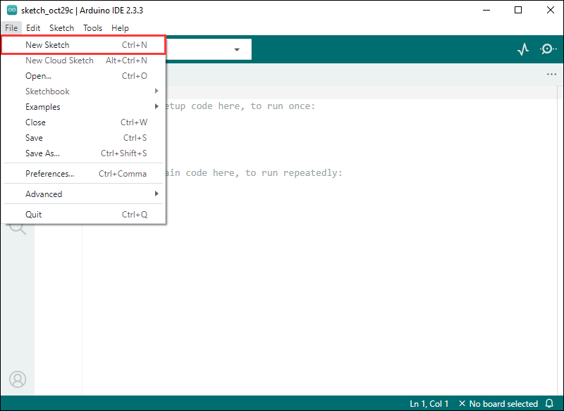
- Enter the code:
void setup() {
  // put your setup code here, to run once:
  Serial.begin(115200);
}

void loop() {
  // put your main code here, to run repeatedly:
  Serial.println("Hello, World!");
  delay(2000);
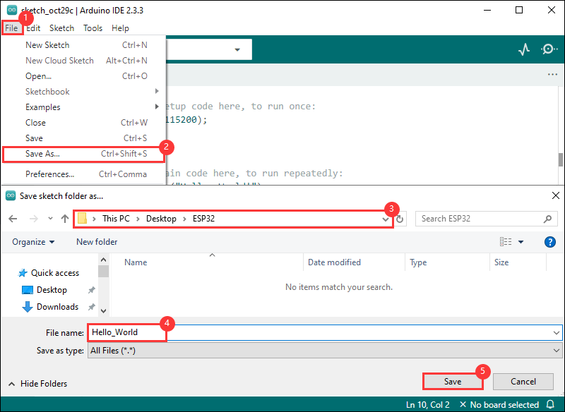
}- Save the project and select
File->Save As.... In the pop-up menu, select the path to save the project, and enter a project name, such as Hello_World, clickSave
Compile and Flash Demos
- Select the corresponding development board, take the ESP32S3 motherboard as an example:
①. Click to select the dropdown menu option Select Other Board and Port;
②. Search for the required development board model esp32s3 dev module and select;
③. Select COM Port;
④. Save the selection.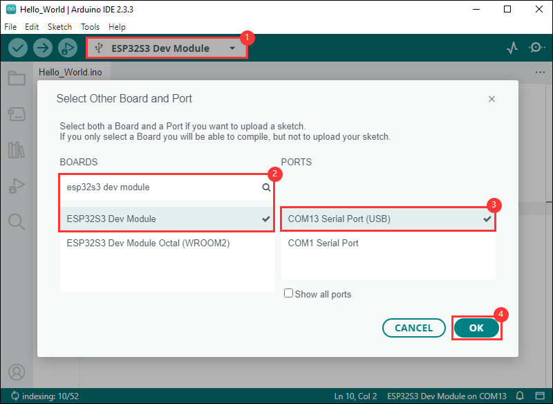
- If the ESP32S3 mainboard only has a USB port, you need to enable USB CDC, as shown in the following diagram:
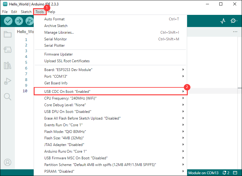
- Compile and upload the program:
①. Compile the program; ②. Compile and download the program; ③. Download successful.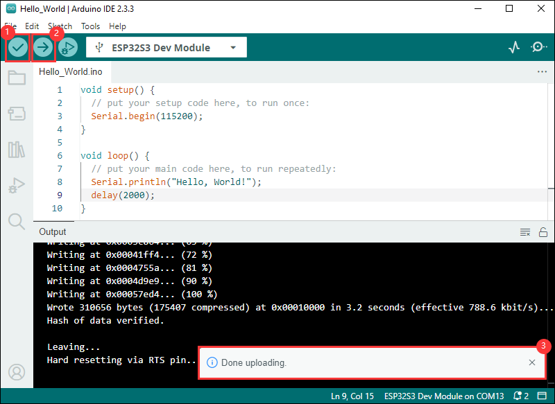
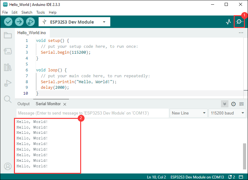
- Open the Serial Monitor window, and the demo will print "Hello World!" every 2 seconds, and the operation is as follows:
Demos
| Demo | Basic Description | Dependency Library |
|---|---|---|
| 01_OneButton | Button interaction and LCD display | OneButton |
| 02_ADC_Read | ADC sampling | - |
| 03_IIC_BME68X_Sensor | Drive I2C module | BME68x Sensor library |
| 04_UART0 | Serial communication | - |
| 05_LCD_Button | Button operation to switch images, control backlight | OneButton,TFT_eSPI |
| 06_LCD_Time | Display date and time on LCD | TFT_eSPI |
| 07_SD_Test | Perform add, delete, modify, and check operations on SD card files | - |
| 08_SD_LCD | Read JPEG images from SD card and display on screen | TFT_eSPI,JPEGDecoder |
| 09_BLE_LCD | ESP32-S3 interacts with BLE and LCD, can act as a BLE server to send and receive data and display on LCD | TFT_eSPI,ESP32-BLE-Keyboard-master |
| 10_BLE_UART | ESP32-S3 interacts with BLE, can act as a BLE server to send and receive data and display message content via UART | ESP32-BLE-Keyboard-master |
| 11_BLE_Keyboard | Simulate BLE keyboard | ESP32-BLE-Keyboard-master |
| 12_WIFI_AP_LCD | Interact with Wi-Fi and LCD, can act as a Wi-Fi access point to communicate with clients and display on LCD | TFT_eSPI |
| 13_WIFI_TCP_Client | Interact with Wi-Fi and LCD, after connecting to Wi-Fi, attempt to connect to a server, send and receive data, and display on LCD | TFT_eSPI |
| 14_WIFI_TCP_Server | Interact with Wi-Fi and LCD, act as a Wi-Fi server, receive client data and display on LCD | TFT_eSPI |
| 15_WIFI_Web_Server | Interact with Wi-Fi and LCD, act as a Wi-Fi access point server, handle client requests | TFT_eSPI |
| 16_MQTT_sub_pub | Interact with Wi-Fi, MQTT, and LCD, connect to Wi-Fi and MQTT server, send and receive JSON data and display on LCD | ArduinoJson,PubSubClient,TFT_eSPI |
| 17_MQTT_BLE_Keyboard | Integrate BLE keyboard, Wi-Fi, and MQTT, control LCD display | ArduinoJson,PubSubClient,TFT_eSPI,ESP32-BLE-Keyboard-master |
01_OneButton
Program Description
- This routine allows the use of the ESP32-S3-GEEK's boot button as a multifunctional button, capable of performing different actions such as single clicks, double clicks, or long presses. It is suitable for learning about button interaction and LCD display with the ESP32-S3. By operating the button, you can observe changes on the LCD and test its reliability
Hardware connection
- Connect the development board to the computer
Code analysis
- button.attachLongPressStart(LongPressStart, &button):Button event binding
Statements like button.attachLongPressStart(LongPressStart, &button) bind specific functions to different events of the button, allowing the corresponding processing functions to be automatically called when the button is long-pressed, single-clicked, or double-clicked
- button.tick():Continuous monitoring
button.tick() constantly checks the status of the button to determine if any button events have occurred. If an event occurs, the corresponding callback function will be called based on the event type
Code flashing
- Select the development board model ESP32S3 Dev Module (or the exact model) and port
- Flash the code
Result demonstration
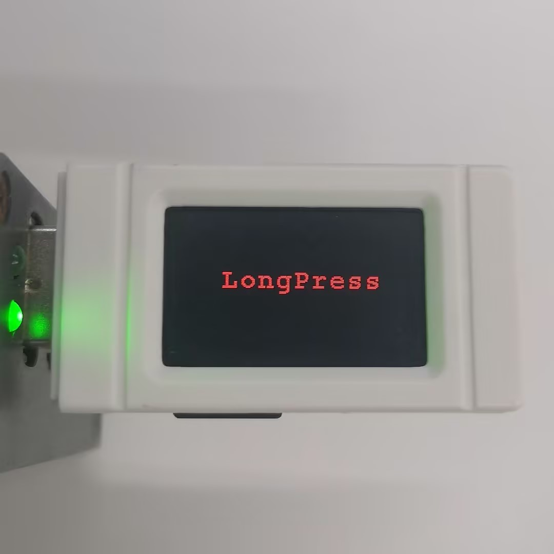
- Perform single clicks, double clicks, or long presses on the button to view the LCD display
02_ADC_Read
Program Description
- This routine uses the ESP32-S3-GEEK's GPIO interface to perform ADC sampling, reading voltages within the 3.3V range. Note that during use, it is important to ensure common grounding and not to exceed the measurement range. It is suitable for learning about the analog input of the ESP32-S3, allowing the reading of analog values from specific pins, observing changes, and testing stability
Hardware connection
- Connect the board to the computer using a USB cable
- Connect both ends of the SH1.0 3PIN Dupont wire to the development board and the voltage source to be measured
- The pin connected to the development board's GPIO6 is used to read the measured voltage
- Connect the development board's GND pin (either the GND of the IIC or UART interface is fine) to the GND pin of the voltage source to ensure it is connected to the ground of the voltage source
Code analysis
- setup()
- Initialize the backlight control pin to a low level
- Open serial communication and set the baud rate to 115200
- Set the ADC resolution to 12 bits
- loop()
- Define variables to store the ADC's raw value and voltage value
- Read the ADC raw value and voltage value from the specified pin
- Output the ADC value via the serial port
- Introduce a 100 millisecond delay
Code flashing
- Select the development board model ESP32S3 Dev Module (or the exact model) and port
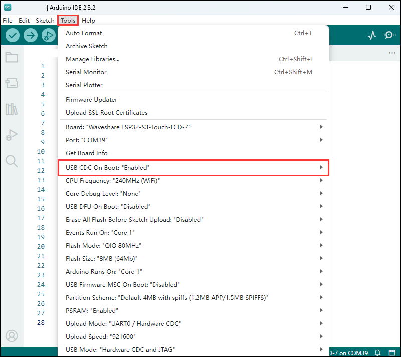
- Set the development board parameters: Enable
USB CDC On Boot
- Flashing code
Result Demonstration
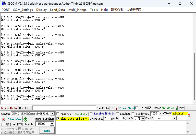
- Result demonstration:Use a serial port debugging assistant to observe the data read from the AD pin,ADC analog value refers to the ADC's raw analog reading,ADC millivolts value refers to the voltage value converted from the ADC reading
03_IIC_BME68X_Sensor
Program Description
- This routine can use the ESP32-S3-GEEK's IIC hardware interface to drive I2C modules. The routine uses the BME680 sensor for demonstration, printing data via the serial port. It is suitable for learning how the ESP32-S3 interacts with the BME68X sensor, allowing you to set pins and communication modes, read various data, and test compatibility and stability
Hardware connection
- Connect the development board to the computer
1.Connect the BME680 environmental sensor to the ESP32-S3-GEEK development board 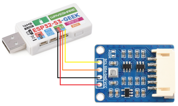
Code analysis
- setup()
- Use
analogWriteto set the backlight control pinPIN_BLto 0, turning off the backlight - Initialize I2C communication with
Wire.begin(PIN_SDA, PIN_SCL)(the commentedSPI.begin()indicates that SPI mode can also be used, but it is not enabled here) - Initialize serial communication and set the baud rate to 115200
- Wait for the serial connection to be ready
- Initialize the BME68X sensor according to the configured communication method (I2C here). If there are any errors or warnings during initialization, corresponding messages will be output to the serial port
- Set the sensor's temperature, pressure, and humidity measurement configurations, and set the heater configuration
- Output the header row of the data to the serial port, including the timestamp, temperature, pressure, humidity, gas resistance, and status
- Use
- loop()
- Create a
bme68xDatastructure object data to store sensordata - Set the sensor's operating mode to forced mode (
BME68X_FORCED_MODE) - Delay for the duration of the sensor's measurement to ensure the data is ready
- Unlock mutual exclusion lock, allowing other parts of the program to continue accessing the LVGL API
- If data is successfully obtained, store it in the
datastructure usingbme.getData(data), and output the timestamp, temperature, pressure, humidity, gas resistance, and status information to the serial port
- Create a
Code flashing
- Select the development board model ESP32S3 Dev Module (or the exact model) and port
- Set the development board parameters: Enable
USB CDC On Boot - Flash the code
Result demonstration
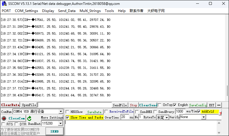
- You can observe the read data on the serial monitor or serial debugging assistant. From left to right, it displays the temperature (degrees Celsius), atmospheric pressure (hectopascals), relative humidity (%RH), altitude (m), and gas resistance (ohms) measured by the BME68x sensor
04_UART0
Program Description
- This routine allows the use of the ESP32-S3-GEEK to open the UART0 serial port and use a serial port debugging assistant for serial communication. It is suitable for learning about ESP32-S3 serial communication, capable of receiving and transmitting data, and testing stability and accuracy
Hardware connection
- Connect the board to the computer using a USB cable
- You can connect USB-to-UART universal serial communication modules for serial communication, with the CH343 USB UART Board as an example
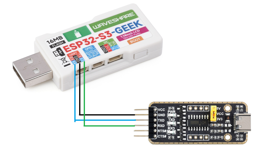
Code analysis
- setup()
- Use
analogWriteto set the backlight control pinDEV_BL_PIN(7)to 0, turning off the backlight - Initialize serial communication and set the baud rate to 115200
- Use
- loop()
- Check if there is any data to read from the serial port. If there is, enter a loop to process the input data
- Create a character array
bufferto store the input data, and a variablebufferSizeto keep track of the amount of data in the buffer - In the loop, read a character at a time and store it in the buffer, increasing the buffer size accordingly
- When the buffer is full (reaches the array size) or a newline character is read, output the data in the buffer through the serial port, then delay for 10 milliseconds
- Finally, reset the buffer size to 0, and use the
memsetfunction to clear the buffer to zero, preparing it for the next input
Code flashing
- Select the development board model ESP32S3 Dev Module (or the exact model) and port
- Flash the code
Result demonstration
- Use the serial port debugging assistant for serial communication, receiving data from the serial port and outputting the received data through the same serial port
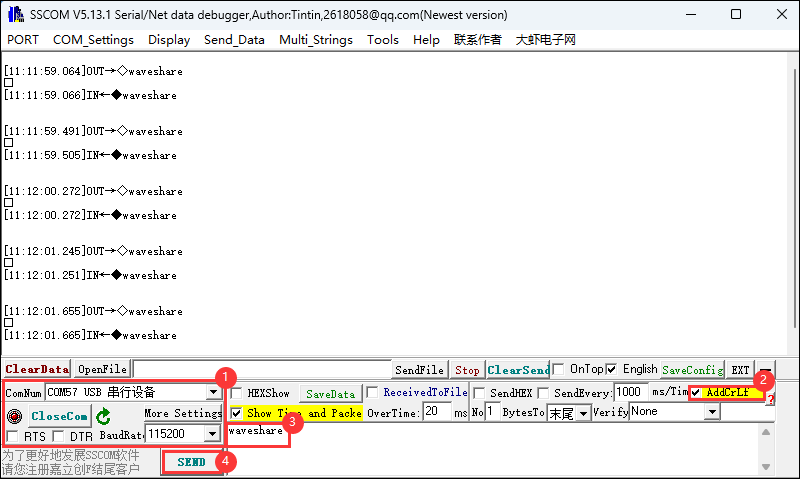
05_LCD_Button
Program Description
- This routine allows the use of the ESP32-S3-GEEK's boot button to turn on the LCD and switch to the next image with a short press, and turn off the LCD with a long press. It is suitable for learning about button interaction and LCD image display on the ESP32-S3. You can switch images and control the backlight through button operations to test stability
Hardware connection
- Connect the development board to the computer
Code analysis
- setup()
- In this program, the
setup()function is executed once when the program starts. It first initializes serial communication with a baud rate of 115200 for potential debugging output. Then, it callsConfig_Init()andLCD_Init()to initialize specific hardware configurations and the LCD to ensure it works properly. It clears the LCD screen to black withLCD_Clear(BLACK)to provide a clean background for display content. The LCD backlight brightness is set to 1000 to ensure the screen is bright enough. A new image object is created and the initial imagegImage_pic1is drawn. Callback functions for long press start and click are set for the button object, pointing toLongPressStartandClickfunctions, respectively. The long press interval is set to 1000 milliseconds to prepare for interactive operations
- In this program, the
- Click(void *oneButton)
- When the button is clicked, this function is called. It first sets the LCD backlight brightness to 1000, then creates a new black image object. By incrementing the
clickvariable and controlling it in a loop, it switches to display different images (gImage_pic1,gImage_pic2,gImage_pic3) based on theclickvalue, providing interactive functionality to switch LCD images with button clicks
- When the button is clicked, this function is called. It first sets the LCD backlight brightness to 1000, then creates a new black image object. By incrementing the
Code flashing
- Select the development board model ESP32S3 Dev Module (or the exact model) and port
- Flash the code
Result demonstration
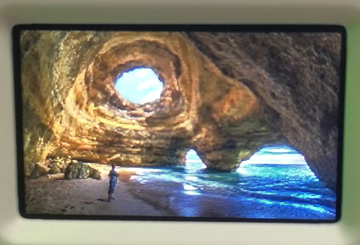
- Short press the boot button to switch images
06_LCD_Time
Program Description
- This routine allows the ESP32-S3-GEEK to connect to Wi-Fi to obtain the current time and display the date and time on the LCD and the serial port debugging assistant. It is suitable for learning about Wi-Fi connection and time synchronization with the ESP32-S3, allowing you to connect to a specific network, synchronize the time, display the date and time on the LCD, and test stability and accuracy
Hardware connection
- Connect the development board to the computer
Additional preparations
- Use a PC to turn on a hotspot, select "Any Available Frequency" for the network band, and change the ssid and password to the Wi-Fi name and password you want to connect to.
utcOffsetInSeconds is the time zone we need to obtain the time for. For example, for Beijing, in the GMT+8 zone, it would be 86060=28800
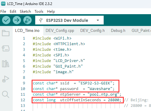
- Note: When the ESP32-S3-GEEK is connected to the same Wi-Fi network as a PC in STA (Station) mode, the Wi-Fi it connects to must have a 2.4GHz band. If there is no 2.4GHz band available, then the network band should be set to "Any Available Frequency". In this case, we directly select "Any Available Frequency"
Code analysis
setup():- Display "Wifi Connecting..." on the LCD to inform the user that the device is attempting to connect to Wi-Fi. Initiate the connection process with WiFi.begin(ssid, password) using the specified network name and password. Enter a loop waiting for the connection to succeed. During this process, print "Connecting to WiFi..." to the serial port every 1000 milliseconds to let the user know the connection progress. Once connected, clear the LCD screen and display "Wifi Connected" to prepare for subsequent network-dependent operations
Code flashing
- Select the development board model ESP32S3 Dev Module (or the exact model) and port
- Set the development board parameters: Enable
USB CDC On Boot - Flash the code
Result demonstration
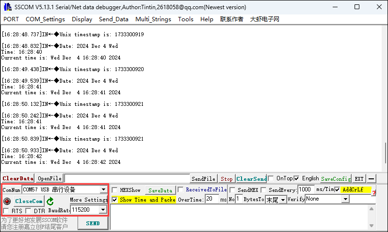
- The LCD displays the real-time time and date. You can see the printed time and date using the Arduino serial monitor or serial debugging assistant
07_SD_Test
Program Description
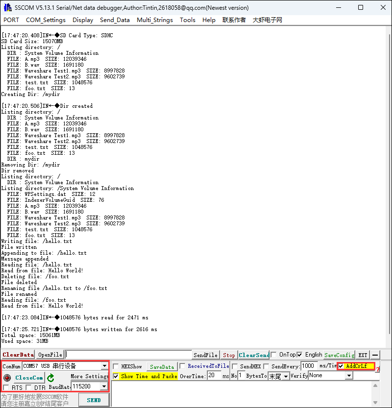
- This routine allows the use of the ESP32-S3-GEEK's TF card slot. By inserting an TF card into the slot and opening the serial port debugging assistant, you can see the ESP32-S3-GEEK performing add, delete, modify, and check operations on the TF card's files. It is suitable for learning about interactions between the ESP32-S3 and the TF card, allowing for various file operations and testing stability and reliability
Hardware connection
- Connect the development board to the computer
- Insert the TF card into the development board
Code analysis
setup()- First, set the device output connected to
DEV_BL_PINto 0, initialize serial communication, start the HSPI bus, and set the clock divider. Then, attempt to initialize the connection to the TF card on the specific pin. If successful, determine the TF card type and display its capacity. Afterward, perform a series of file system operations on the TF card, such as listing directories, creating and deleting directories, reading and writing files, renaming files, and testing read/write performance, while also outputting the total and used space of the TF card
- First, set the device output connected to
Code flashing
- Select the development board model ESP32S3 Dev Module (or the exact model) and port
- Set the development board parameters: Enable
USB CDC On Boot - Flash the code
Result demonstration
08_SD_LCD
Program Description
- This routine allows the use of the ESP32-S3-GEEK's TF card slot to read images from the TF card. After storing photo images on the TF card and inserting it into the slot, the ESP32-S3-GEEK can read the photos from the TF card and display them on the LCD, or create a dynamic image by refreshing the photos. It is suitable for learning about interactions between the ESP32-S3, TF card, and TFT screen, allowing the reading of JPEG images from the TF card and displaying them on the screen to test stability and reliability
TF Card Preparation
- You can use a card reader to store photos from the path ..\ESP32-S3-GEEK-Demo\Arduino\pic on the TF card, or store your own photos. It is best to resize the images to 240x135 for optimal display effect
Hardware connection
- Connect the board to the computer using a USB cable
- Insert the TF card into the development board
Code analysis
- setup()
- Initialize the serial port and TFT display
- Configure TF card SPI communication and attempt to mount the TF card
- Determine the type of TF card and output its capacity information
- drawSdJpeg()
- Open the image file and decode it with a JPEG decoder. If successful, display image information and call
jpegRender
- Open the image file and decode it with a JPEG decoder. If successful, display image information and call
- jpegRender()
- Handle the display of the image on the TFT, including edge cases, and record the display time
Code flashing
- Select the development board model ESP32S3 Dev Module (or the exact model) and port
- Set the development board parameters: Enable
USB CDC On Boot - Flash the code
Result demonstration
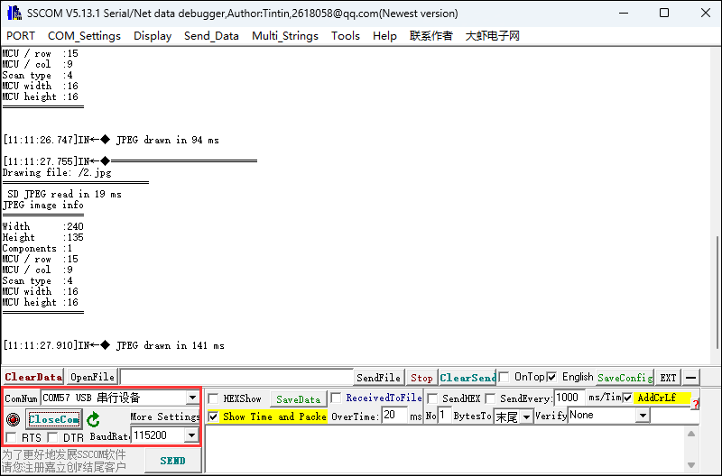
- You can view the cyclically printed image information in the Arduino serial monitor or serial debugging assistant. At this time, the LCD screen will cyclically display the images from the TF card
09_BLE_LCD
Program Description
- This project uses the ESP32-S3-GEEK development board to open Bluetooth BLE, and uses a mobile phone with a Bluetooth debugging assistant to connect to the ESP32-S3-GEEK for Bluetooth BLE communication. The messages sent and received are displayed on the LCD. It is suitable for learning how ESP32-S3 interacts with BLE and LCD, and can serve as a BLE server to send and receive data and display it on the LCD, testing stability and reliability
Hardware connection
- Connect the development board to the computer
Code analysis
- setup():
- Initialize the relevant configurations and LCD display
- Start serial communication, set the baud rate to 115200
- Clear the LCD to a black background and set the backlight brightness
- Create an image buffer and draw a predefined image
- Initialize the BLE device and set the name
- Create a BLE server and callback functions
- Create BLE services and characteristics for sending and receiving, and set properties and callback functions
- Start the service and begin advertising, output a prompt message via the serial port waiting for the client to connect
- loop():
- Serial data reading and sending:
- If there is data to read from the serial port, read it in a loop and add it to the buffer. When a newline character is encountered, process the data and send it to the BLE client Also, output the sent message via the serial port and clear the buffer for the next rea
- Low-power operation (optional): Add low-power operation code here if needed
- Delay for 10 milliseconds to reduce power consumption and improve stability
- BLE connection status handling:
- If the connection status changes from connected to disconnected, delay and then start advertising again
- If the connection status changes from disconnected to connected, add code to handle the new connection
- Serial data reading and sending:
Code flashing
- Select the development board model ESP32S3 Dev Module and port
- Set the development board parameters: Enable
USB CDC On Boot - Flash the code
Result demonstration
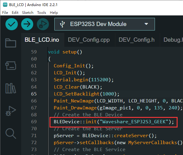
BLEDevice::init("Waveshare_ESP32S3_GEEK"), "Waveshare_ESP32S3_GEEK" is the Bluetooth device name
- Use the mobile phone to open the Debugging Tool to scan and connect the device
- Use the Bluetooth debugging assistant to send the message to ESP32-S3-GEEK, and the ESP32-S3-GEEK will display the message on the LCD after receiving it


- ESP32-S3-GEEK uses USB to UART tool to connect to the PC, open the serial debugging assistant, and send the UART message as a Bluetooth message to the mobile phone. Make sure to check "AddCrLf" options when sending the message. The sent message will be displayed on the LCD. On the mobile device, observe if it receives the Bluetooth message


10_BLE_UART
Program Description
- This demo allows the ESP32-S3-GEEK to activate Bluetooth Low Energy (BLE). You can use a smartphone's Bluetooth debugging tool to connect to the ESP32-S3-GEEK, enabling BLE communication between the two devices. The sent and received messages will be displayed on the serial monitor, similar to 09_BLE_LCD. However, this version doesn't activate the LCD, reducing power consumption significantly by using UART to display message content.For operations, please refer to 09_BLE_LCD
11_BLE_Keyboard
Program Description
- This routine can use the ESP32-S3-GEEK as a Bluetooth keyboard. By connecting to the ESP32-S3-GEEK via PC Bluetooth, you can perform a series of keyboard single-key or combination operations. This example program will repeatedly lock and unlock the computer screen. Pressing the boot button to restart the power will exit the program. It is suitable for simulating a BLE keyboard with the ESP32-S3-GEEK, sending text and key commands, and testing stability and reliability
- The PC can automatically lock and unlock the screen. Press the boot button to restart and exit the program
Hardware connection
- Connect the development board to the computer
Code analysis
- setup():
- Start serial communication, set the baud rate to 115200 for debugging output
- Output the message "Starting BLE work!" on the serial port
- Initialize the Bluetooth keyboard object
bleKeyboard, passing in the device name, manufacturer name, and battery report interval, then call thebeginmethod to start the Bluetooth keyboard
- loop():
- Check if the Bluetooth keyboard is connected. If connected:
- Output the message "Sendin'Waveshare'..." on the serial port, then send the string "waceshare" using the
printmethod. - Delay for 500 milliseconds.
- Output the message "Sendin Enter key..." on the serial port, then send the enter key (
KEY_RETURN) using thewritemethod. - Delay for 500 milliseconds.
- Output the message "Sendin Ctrl+Alt+Delete..." on the serial port, press the left Ctrl, left Alt, and Delete keys, then release all keys after a 100 millisecond delay.
- Output the message "Sendin'Waveshare'..." on the serial port, then send the string "waceshare" using the
- Output the message "Waiting 5 seconds..." on the serial port, then delay for 5000 milliseconds, waiting for the next loop
- Check if the Bluetooth keyboard is connected. If connected:
Code Modification
①. Bluetooth name
②.Modify it to your unlock password to perform automatic lock and unlock screen operations. Pressing the boot button to restart the power will exit the program ("waveshare" below is an example password)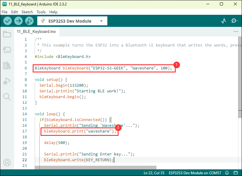
Code flashing
- Select the development board model ESP32S3 Dev Module and port
- Flash the code
Result demonstration
- Use your PC to open Bluetooth and scan for devices to connect
- After a successful connection, a series of keyboard operations will be performed every 5 seconds (output "Waveshare", Ctrl+Alt+Delete)
- The PC can automatically lock and unlock the screen. Press the boot button to restart and exit the program
- You can view the values of individual keys in the BleKeyboard.h file located in the libraries folder
12_WIFI_AP_LCD
Program Description
- This routine allows the ESP32-S3-GEEK to operate in Wi-Fi AP mode. After connecting a PC to its Wi-Fi, you can log in to the IP address and control the LCD display of the ESP32-S3-GEEK through a web interface. It is suitable for learning how the ESP32-S3-GEEK interacts with Wi-Fi and an LCD display, and can serve as a Wi-Fi access point for communication with clients, displaying information on the LCD, and testing stability and reliability
Hardware connection
- Connect the development board to the computer
Code analysis
- setup():
- Call
Config_Init()andLCD_Init()to initialize the relevant configurations and the LCD display - Start serial communication, set the baud rate to 115200 for debugging output
- Set the LCD backlight brightness to 100
- Create a new image buffer, set the rotation angle to 90 degrees, and clear the LCD display to a specific color (0x000f)
- Call
WIFI_AP_Init()to initialize the Wi-Fi access point
- Call
- loop():
- Use
WiFiClient client = server.available();to listen for any clients connecting to the server. - Call the
WIFI_LCD_Control(client)function to handle connected clients, which may perform operations related to the LCD display. The specific functionality depends on the implementation of this function
- Use
Code flashing
- Select the development board model ESP32S3 Dev Module and port
- Flash the code
Result demonstration
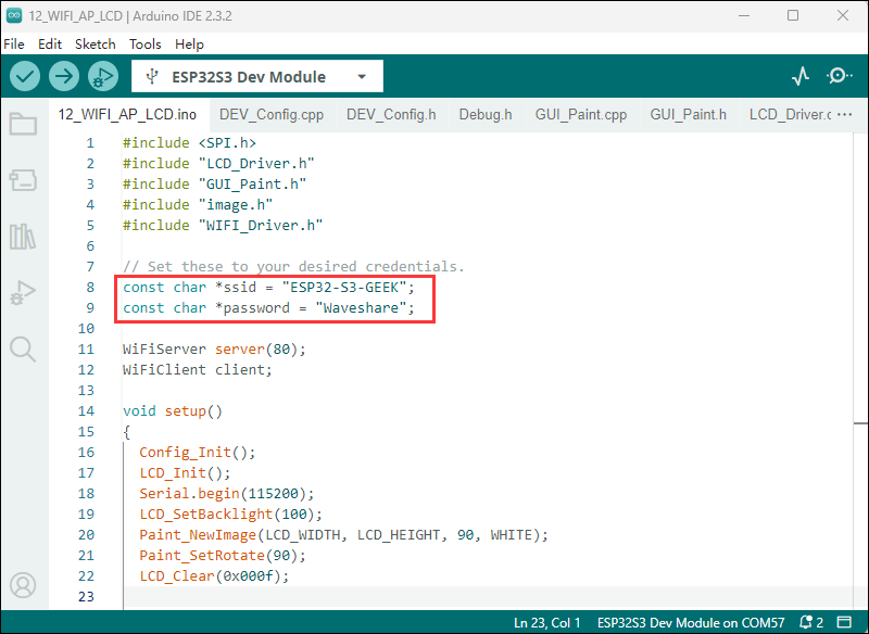
- The ssid is the name of the AP created by the ESP32-S3-GEEK (ESP32-S3-GEEK), and the password is the key required to connect to the AP (Waveshare)
- Use a PC to connect to the ESP32-S3-GEEK's AP. Enter the password "Waveshare"
- If the PC successfully flashs the code but cannot recognize the Wi-Fi, try restarting the power to the development board
- The LCD will display the IP address of the HTTP server
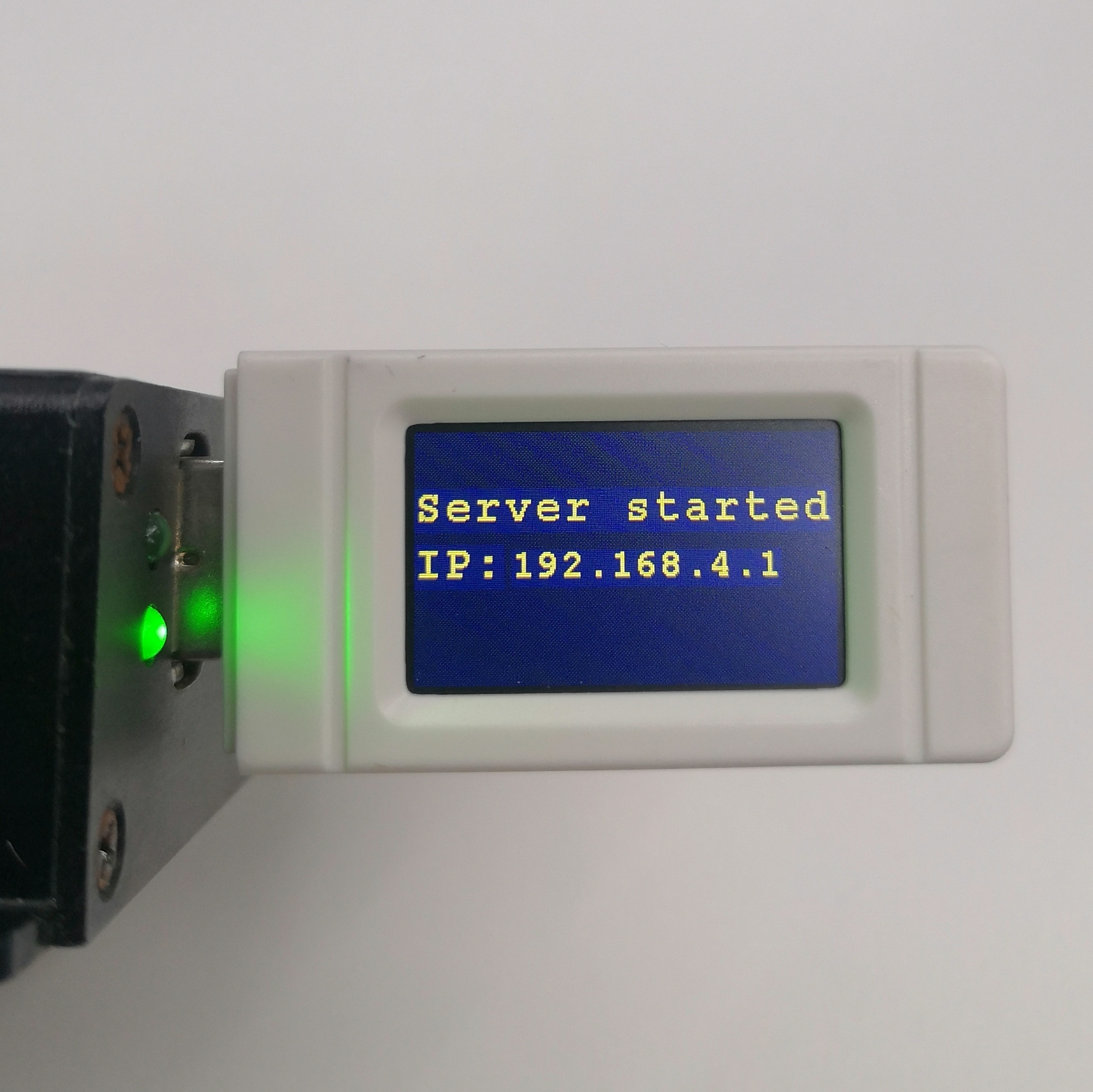
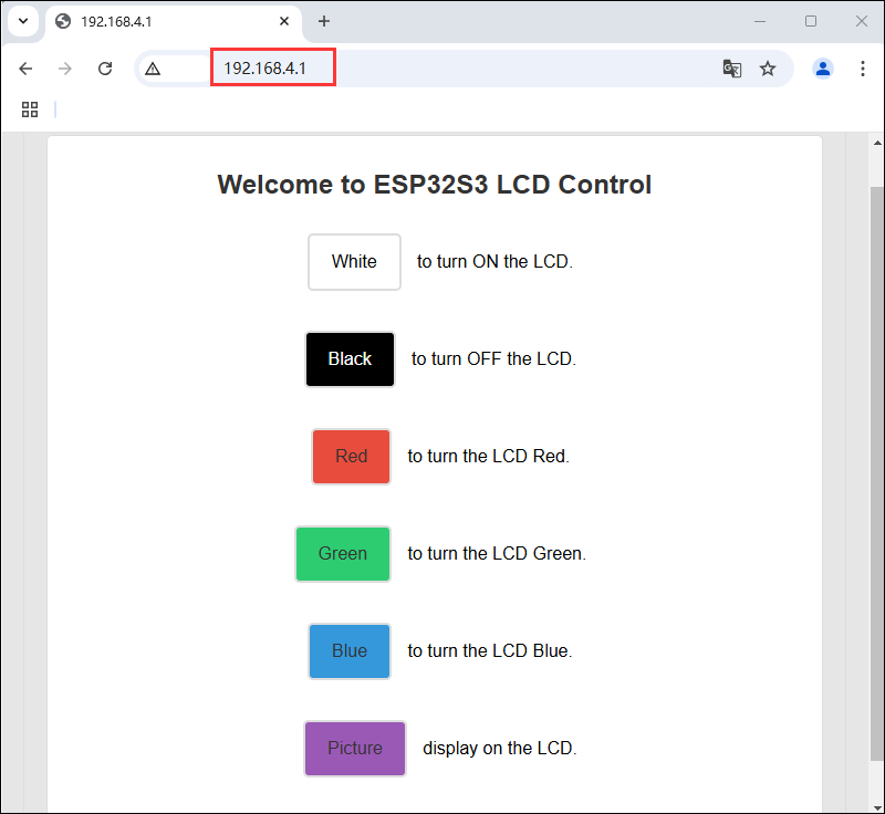
- Use a web browser to log in to the IP address: 192.168.4.1. Control the LCD of the ESP32-S3-GEEK through the buttons on the server. Press different buttons and observe the changes on the LCD. For more display functions of the LCD, you can refer to the LCD program documentation
13_WIFI_TCP_Client
Program Description
- This routine allows the ESP32-S3-GEEK to operate in Wi-Fi STA mode. After connecting to the same Wi-Fi network as a PC or mobile device, it acts as a TCP Client to access a TCP Server created by the PC or mobile device. It establishes TCP communication and displays the received content on the LCD. This is suitable for learning how the ESP32-S3-GEEK interacts with Wi-Fi and an LCD display, connecting to Wi-Fi, attempting to connect to a server, sending and receiving data, and displaying it on the LCD to test stability and reliability
Hardware connection
- Connect the development board to the computer
Code analysis
- intToIpAddress()
- Uses the
sprintffunction to convert the input IP address integer into a string in dotted decimal format and stores it in the character array pointed to by the result pointer
- Uses the
- setup()
- Module initialization:
- Calls
Config_Init()andLCD_Init()to initialize the relevant configurations and the LCD display - Starts serial communication with a baud rate of 115200
- Sets the LCD backlight brightness to 100
- Creates a new image buffer, sets the rotation angle to 90 degrees, and clears the LCD display to a specific color (0x000f)
- Calls
- Wi-Fi connection:
- Sets the Wi-Fi mode to STA (client mode) and disables Wi-Fi sleep to improve response speed
- Attempts to connect to the specified Wi-Fi network using
WiFi.begin(ssid, password) - During the connection process, continuously displays the connection status on the LCD and outputs the connection status information via the serial port
- Upon successful Wi-Fi connection, clears the LCD display, obtains the local IP address, converts it to a string, and displays it on the LCD, while also outputting the connection success and IP address information via the serial port
- Module initialization:
- loop()
- Server connection attempt:
- Displays the information about attempting to connect to the server on the LCD and outputs the corresponding information via the serial port
- Server connection success:
- If successfully connected to the server, clears the LCD display and shows the connection success message
- Sends "Hello world!" data to the server
- Enters a loop where, as long as the client is connected or there is available data, the following actions are taken:
- If there is data to read, reads the data until a newline character is encountered, outputs the read data via the serial port, displays it on the LCD, and sends the received data back to the server
- Outputs the information about closing the current connection via the serial port and stops the client connection
- Connection failed:
- If the server connection fails, outputs the connection failure information via the serial port and stops the client connection
- Delay:
- After each loop, delays for 5000 milliseconds
- Server connection attempt:
Code Modification
①.Use your PC to create a hotspot, select "Any available frequency" for the network band, and ensure that the ssid and password in the program match the Wi-Fi name and password you want to connect to
②.Download a Debugging Tool and modify it to use your local IP address (the 192.168.137.1 provided below is an example IP address)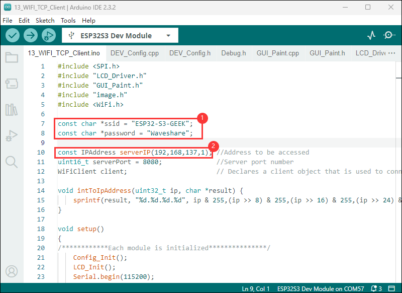
Code flashing
- Select the development board model ESP32S3 Dev Module and port
- Flash the code
Result demonstration
- At this point, the LCD screen will display "Attempting to connect," and after a short while, it will show "Connected"
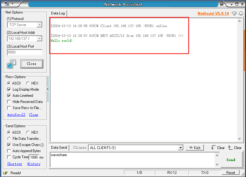
- Modify the parameters in NetAssist, set the protocol type to TCP Server, ensure the local IP address is the same as in the program, set the local port number to 8080, and click "Connect" to establish a connection and engage in TCP communication with the ESP32-S3-GEEK (TCP Client)
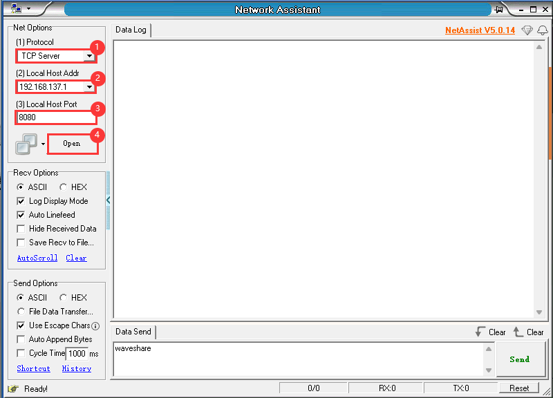
- After a successful connection, the TCP Server will receive the TCP message "Hello world" sent by the ESP32-S3-GEEK, and the LCD will display "Access successful"
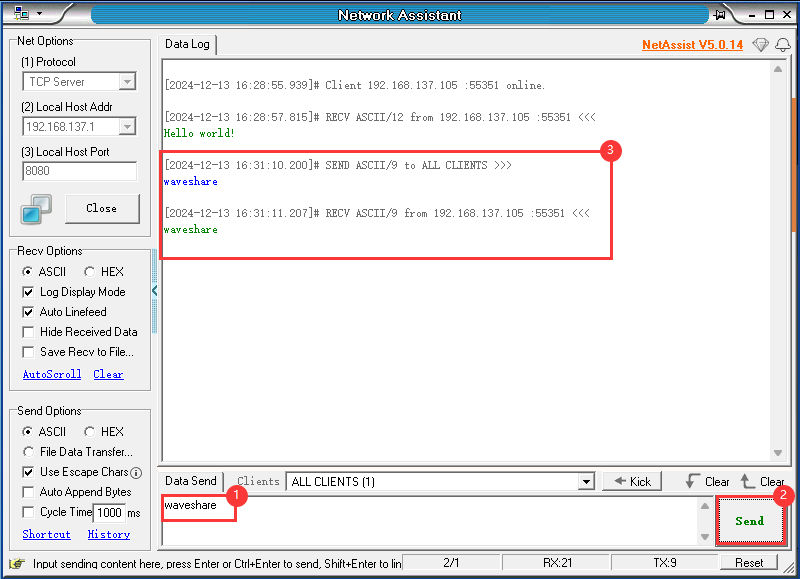
- Through the PC's TCP Server, you can send a TCP message to the ESP32-S3-GEEK. If the message is sent successfully, the ESP32-S3-GEEK, acting as a TCP Client, will receive the message and display its content on the LCD. You can observe the message being displayed on the LCD
- You can also use your mobile phone to create a hotspot with the same name and password as mentioned above, and select the 2.4GHz frequency band
- After turning on the hotspot, you can use a TCP debugging tool to communicate with the ESP32-S3-GEEK via TCP


- Modify the serverIP in the code to the IP address of the TCP server created by your mobile phone (192.168.6.123)


- Flash the code to the ESP32-S3-GEEK. After a successful connection, the TCP Server will receive a TCP message "Hello world" sent by the ESP32-S3-GEEK, and the LCD will display "Access successful". You can use a TCP Server on your mobile phone to send TCP messages to the ESP32-S3-GEEK. If the message is sent successfully, the ESP32-S3-GEEK, acting as a TCP Client, will receive the message and display its content on the LCD. You can observe the message being displayed on the LCD


14_WIFI_TCP_Server
Program Description
- This routine allows the ESP32-S3-GEEK to operate in Wi-Fi STA mode. After connecting to a hotspot created by a PC, it creates a TCP Server. The PC then creates a TCP Client to access the ESP32-S3-GEEK, establishing TCP communication. The GEEK displays the received content. This is suitable for learning how the ESP32-S3-GEEK interacts with Wi-Fi and an LCD display, serving as a Wi-Fi server to receive client data and display it on the LCD, testing stability and reliability
Hardware connection
- Connect the development board to the computer
Code analysis
- intToIpAddress()
- Uses the
sprintffunction to convert the input IP address integer into a string in dotted decimal format and stores it in the character array pointed to by the result pointer
- Uses the
- setup()
- Module initialization:
- Calls
Config_Init()andLCD_Init()to initialize the relevant configurations and the LCD display - Starts serial communication with a baud rate of 115200
- Sets the LCD backlight brightness to 100
- Creates a new image buffer, sets the rotation angle to 90 degrees, and clears the LCD display to a specific color (0x000f)
- Calls
- Wi-Fi connection:
- Sets the Wi-Fi mode to STA (client mode) and disables Wi-Fi sleep to improve response speed
- Attempts to connect to the specified Wi-Fi network using
WiFi.begin(ssid, password) - During the connection process, continuously displays the connection status on the LCD and outputs the connection status information via the serial port
- Upon successful Wi-Fi connection, clears the LCD display
- Module initialization:
- loop()
- Wi-Fi connection status confirmation and server startup:
- Obtains the local IP address, converts it to a string, and outputs it via the serial port, also displaying it on the LCD
- Starts the server with
server.begin(8080), listening on port 8080
- Waiting for client connection:
- Creates a
WiFiClientobject client and attempts to get the connectedclientusingserver.available() - Displays the connection status information on the LCD and outputs the corresponding information via the serial port
- Creates a
- Client connection success handling:
- If a client connects, enters a loop to process the client's data
- When data is available to read, reads the data until a newline character is encountered, then removes the trailing newline and carriage return characters, and displays it on the LCD
- When the client disconnects, stops the current connection and outputs the disconnection information via the serial port
- Wi-Fi connection status confirmation and server startup:
Code Modification
- Use your PC to create a hotspot, select "Any available frequency" for the network band, and ensure that the ssid and password in the program match the Wi-Fi name and password you want to connect to
Code flashing
- Select the development board model ESP32S3 Dev Module and port
- Flash the code
Result demonstration
- After successful flashing of the code, the LCD will display
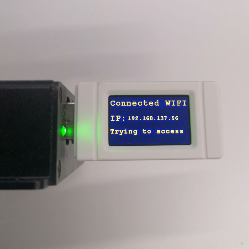
- After the Wi-Fi connection is established, the LCD will display the TCP Server IP. Use a serial port debugging assistant to open a TCP Client for connection and TCP communication with the ESP32-S3-GEEK (TCP Server)
①.Change the port number to match the "TCPClient" port, change the remote address to the IP displayed on the LCD screen, use port number 8080, and click to connect
②.Add a carriage return and line feed
③.Enter the message
④.Send the message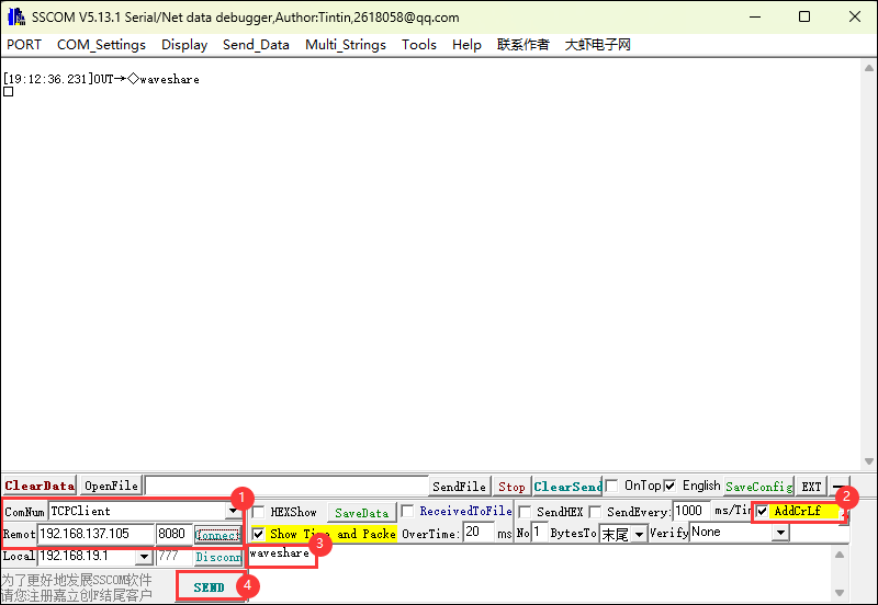
- Once the message is successfully sent, the LCD screen will display
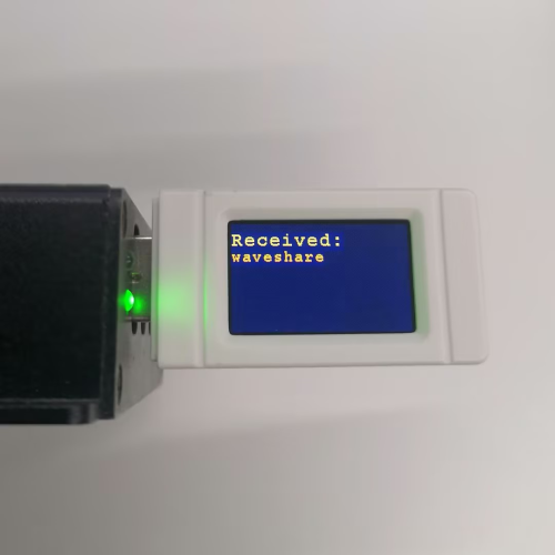
15_WIFI_Web_Server
Program Description
- This routine allows the ESP32-S3-GEEK to operate in Wi-Fi AP mode. After connecting a PC to its Wi-Fi, you can open a serial port debugging assistant. Messages can be sent to the GEEK through the HTTP web page created by the ESP32-S3-GEEK. You can observe the received content on both the serial port debugging assistant and the LCD. This is suitable for learning how the ESP32-S3-GEEK interacts with Wi-Fi and an LCD display, serving as a Wi-Fi access point server, handling client requests, and testing stability and reliability
Hardware connection
- Connect the development board to the computer
Code analysis
- setup()
- Calls
Config_Init()andLCD_Init()to initialize the relevant configurations and the LCD display - Starts serial communication with a baud rate of 115200
- Sets the LCD backlight brightness to 100
- Creates a new image buffer, sets the rotation angle to 90 degrees, and clears the LCD display to a specific color (0x000f)
- Calls
WIFI_AP_Init()to initialize the Wi-Fi access point
- Calls
- loop()
- Listens for any clients connecting to the server using
WiFiClient client = server.available(); - Calls the
WIFI_Web_Server(client)function to handle connected clients. The specific functionality depends on the implementation of this function and may involve providing web services or handling specific network requests
- Listens for any clients connecting to the server using
Code Modification
- Use your PC to create a hotspot, select "Any available frequency" for the network band, and ensure that the ssid and password in the program match the Wi-Fi name and password you want to connect to
Code flashing
- Select the development board model ESP32S3 Dev Module and port
- Flash the code
Result demonstration
- After successful flashing, use a PC to connect to the ESP32-S3-GEEK's AP
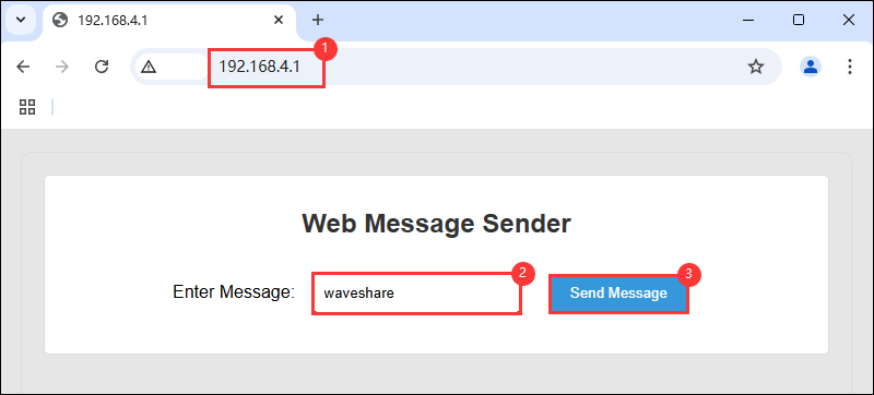
- The LCD will display the IP address of the HTTP server. Use a browser to log in to the IP:192.168.4.1
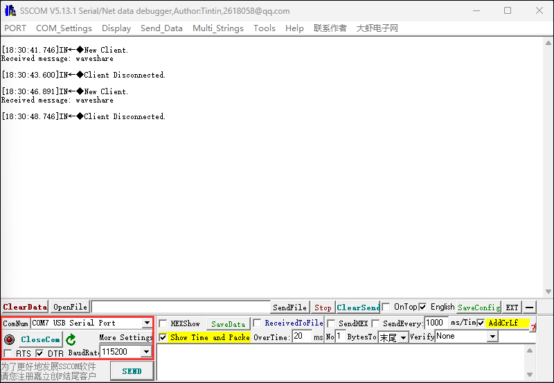
- Connect the ESP32-S3-GEEK's UART interface to the PC using a USB-to-UART tool and open a serial port debugging assistant
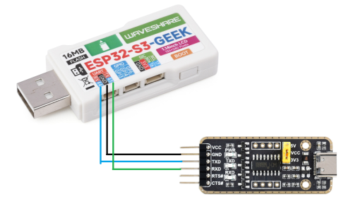
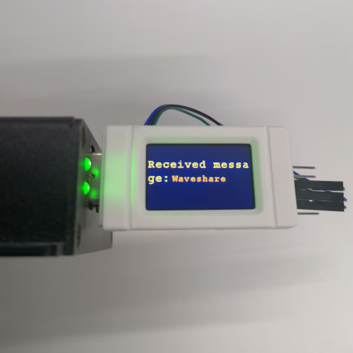
- You can enter text content on the HTTP web page and send an HTTP request to the ESP32-S3-GEEK. The received content can be displayed on both the serial port debugging assistant and the LCD
16_MQTT_sub_pub
Program Description
- This routine allows the ESP32-S3-GEEK to operate in Wi-Fi STA mode. After connecting to Wi-Fi, it uses the Microsnow Cloud platform to perform MQTT communication, subscribe to and publish topics, and achieve long-distance transmission of information. It is suitable for learning how the ESP32-S3-GEEK interacts with Wi-Fi, MQTT, and an LCD display, connecting to Wi-Fi and MQTT servers, sending and receiving JSON data, and displaying it on the LCD to test stability and reliability
Hardware connection
- Connect the development board to the computer
Code analysis
- callback()
- Converts the received byte array into a string
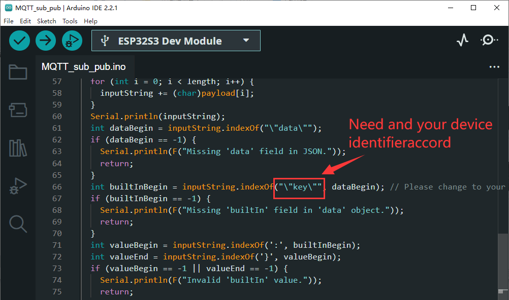
inputString - Searches for specific JSON fields in the string, such as
"data"and"key"(which can be modified to specific data identifiers as needed - Extracts the value of the
"builtIn"field and performs different actions based on its value. If the value is 0, it displays "close!" on the LCD; otherwise, it displays "open!", and also outputs the corresponding information via the serial port
- Converts the received byte array into a string
- setup_wifi()
- Displays "Wifi Connecting..." on the LCD
- Outputs the Wi-Fi network name being connected to via the serial port
- Sets the Wi-Fi mode to STA (client mode) and attempts to connect using the specified SSID and password
- During the connection process, continuously outputs the connection status information via the serial port until the connection is successful
- After a successful connection, clears the LCD screen and displays "Wifi Connected", while also outputting the local IP address via the serial port
Code Modification
- Ensure that the hotspot name and password you use match those in the code
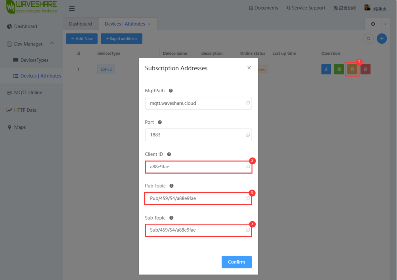
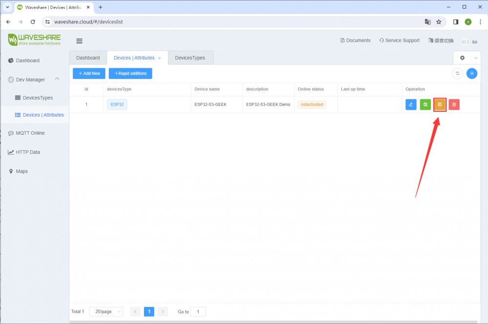
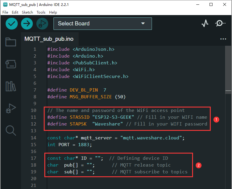
- After registering an account and creating a device on the Microsnow Cloud platform, you can find the device's Client ID, Pub Topic, and Sub Topic by checking the "View Address" for the newly created device. Write these values into the routine to assign them, which will be used for the ESP32-S3-GEEK to connect to its own cloud platform device
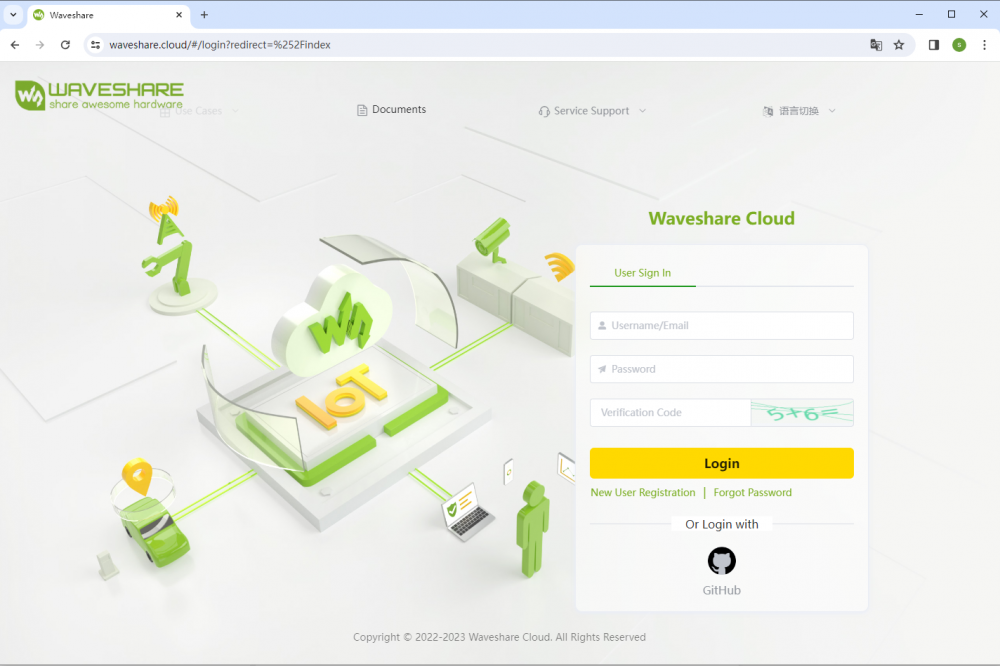
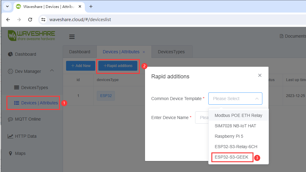
- When you are the first time to register on the Waveshare cloud, you need to create a new device according to the tutorial
- After creating, you can set the corresponding configuration in the Arduino IDE according to ESP32SDK tutorial.
- After configuration, you can find the Client ID, Pub Topic, and Sub Topic of the newly created device on Waveshare's cloud platform under "View Address". You can assign these values in the code to facilitate ESP32-S3-GEEK's connection to your cloud platform device.
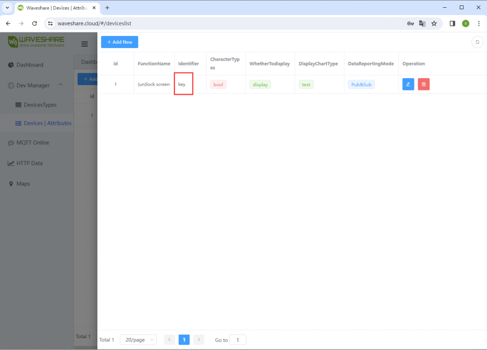
- In the callback function, you can modify the identification tag to our device attribute identifier created on the cloud platform.
Code flashing
- Select the development board model ESP32S3 Dev Module and port
- Flash the code
Result demonstration
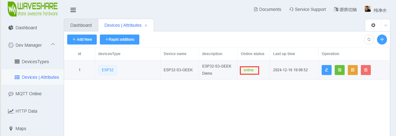
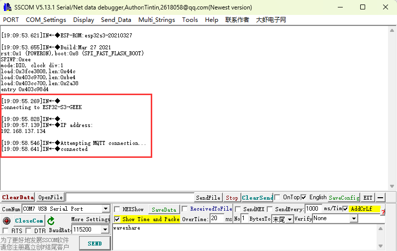
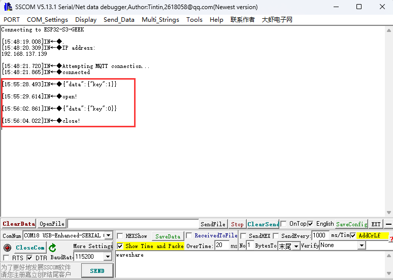
- After flashing the code, once the Wi-Fi connection is established, observe whether the device goes online on the Microsnow Cloud platform. If it does not, you can try refreshing the web page or use a USB-to-UART connection to the PC to check the Wi-Fi and MQTT connection status via a serial port debugging assistant. The LCD screen will also display the connection status of Wi-Fi and MQTT
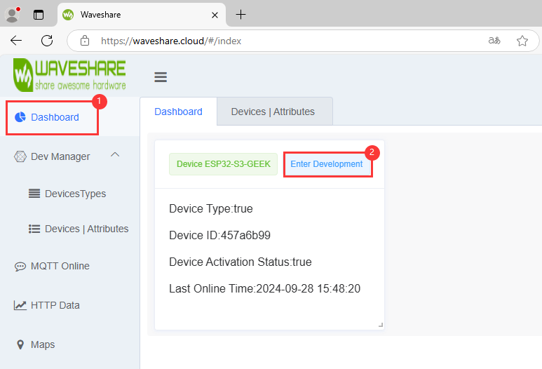
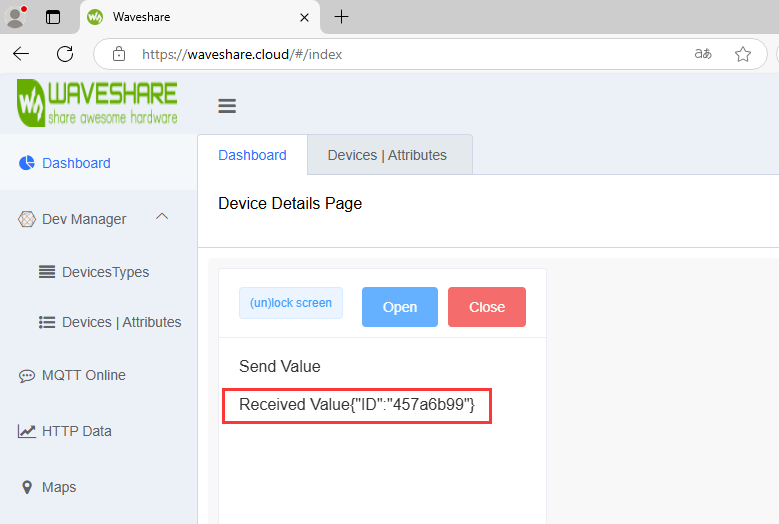
- After successfully connecting the ESP32-S3-GEEK to the Microsnow Cloud, you can send MQTT messages through the Dashboard
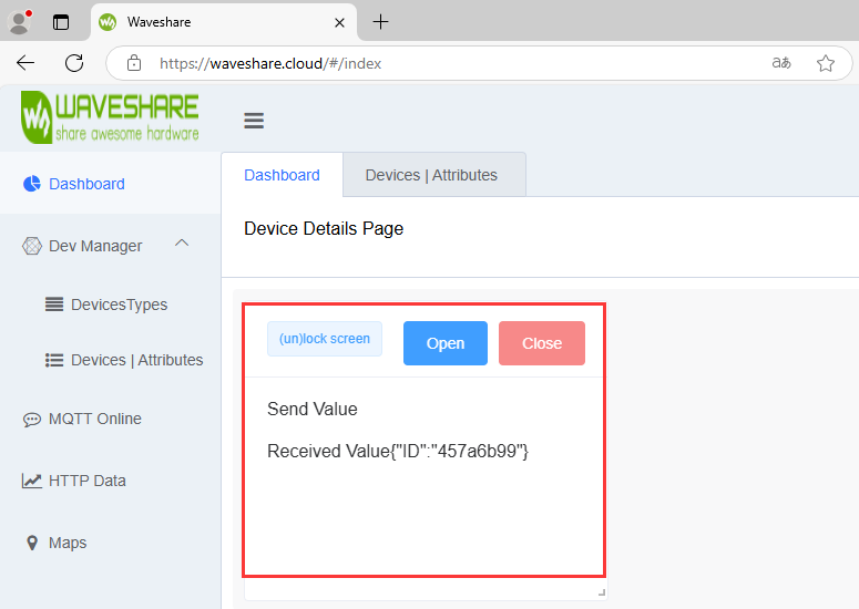
- We can see different feedback for changes in the device's attribute values (e.g.:"key") on both the LCD and the serial port debugging assistant. Additionally, we can observe the data sent from the ESP32-S3-GEEK to the Microsnow Cloud device in the device's received values (the accepted value is your own Client ID, and you can later send back the return value or status of the key to the Microsnow Cloud). This completes the implementation of MQTT data uplink and downlink, as well as subscribing to and publishing topics
17_MQTT_BLE_Keyboard
Program Description
- This routine allows the ESP32-S3-GEEK to operate in Wi-Fi STA mode and Bluetooth. After connecting to Wi-Fi and Bluetooth, it uses the Microsnow Cloud platform to enable remote Bluetooth screen locking and password-based screen unlocking, with more key combinations awaiting your development. It is suitable for integrating BLE keyboard, Wi-Fi, and MQTT with the ESP32-S3-GEEK, controlling LCD display, and testing stability and reliability
Hardware connection
- Connect the development board to the computer
Code analysis
- callback()
- Acts as a callback function for MQTT subscription to handle received messages
- Prints the topic of the received message, then converts the received byte array into a string
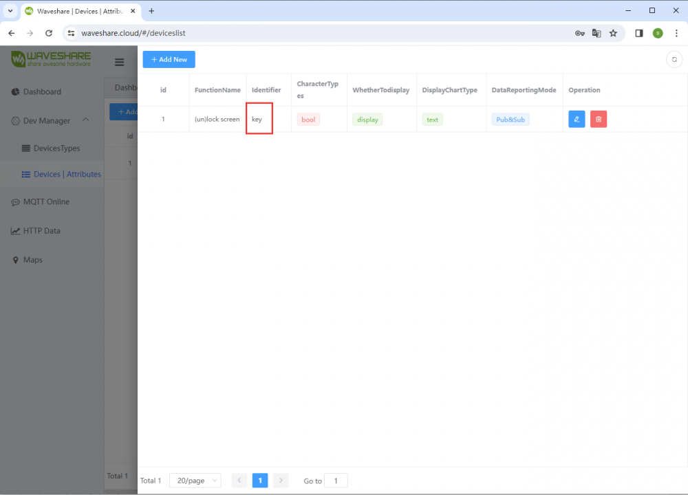
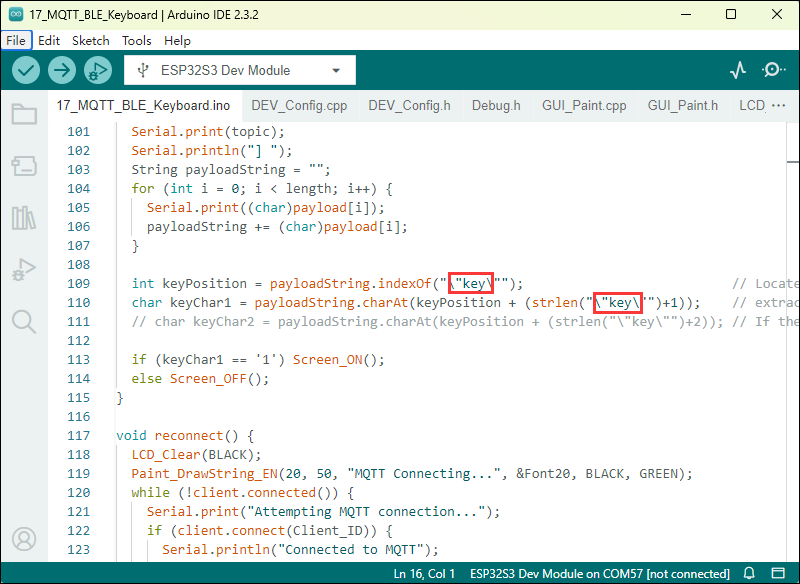
- Searches for a specific JSON field "key" in the string,if your identifier is not "key",you will need to modify the code
- Extracts the value of the "key" field and calls the
Screen_ONorScreen_OFFfunction based on whether the value is "1" or other cases
- setup_wifi()
- Displays "Wifi Connecting..." on the LCD
- Outputs the name of the Wi-Fi network being connected to via the serial port
- Sets the Wi-Fi mode to STA (client mode) and attempts to connect using the specified SSID and password
- During the connection process, continuously outputs the connection status information via the serial port until the connection is successful
- After a successful connection, clears the LCD screen and displays "Wifi Connected" while also outputting the local IP address via the serial port
Code Modification
- Ensure that the hotspot name and password match those in the code (2.4GHz or any available frequency)
- After registering an account and creating a device on the Microsnow Cloud platform, you can find the device's Client ID, Pub Topic, and Sub Topic by checking the "View Address" for the newly created device. Write these values into the routine to assign them, which will be used for the ESP32-S3-GEEK to connect to its own cloud platform device
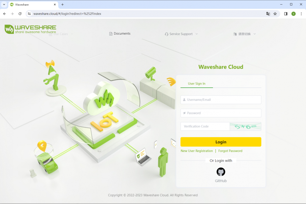
- When you are the first time to register on the Waveshare cloud, you need to create a new device according to the tutorial
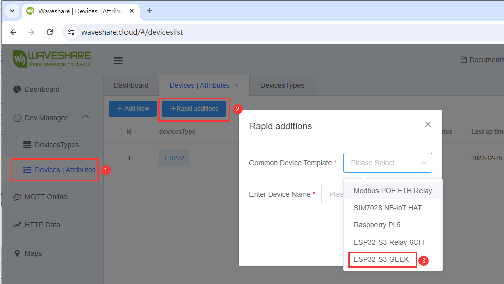
- After creating, you can set the corresponding configuration in the Arduino IDE according to ESP32SDK tutorial
- After configuration, you can find the Client ID, Pub Topic, and Sub Topic of the newly created device on Waveshare's cloud platform under "View Address". You can assign these values in the code to facilitate ESP32-S3-GEEK's connection to your cloud platform device
- Ensure that the bluetooth name and password match those in the code
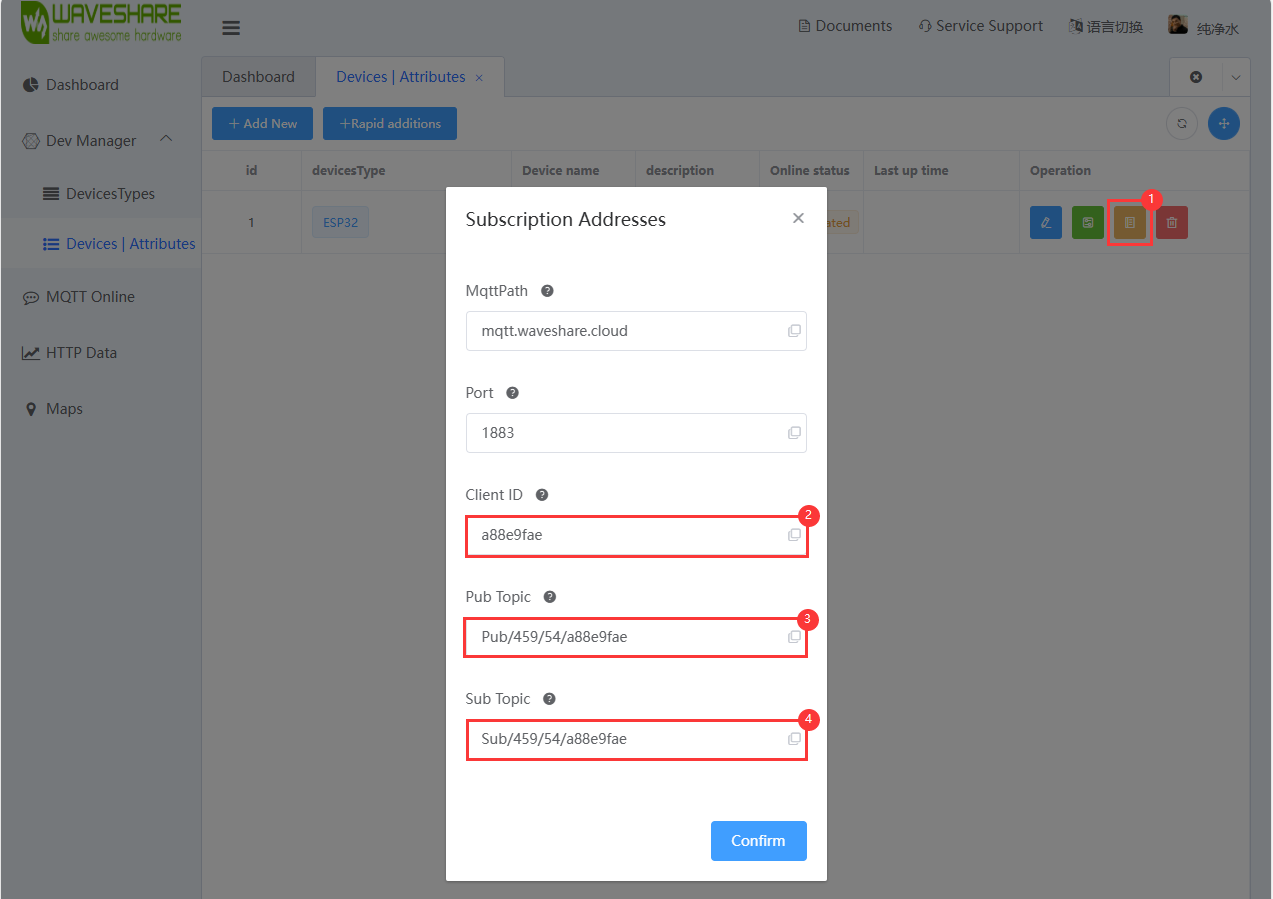
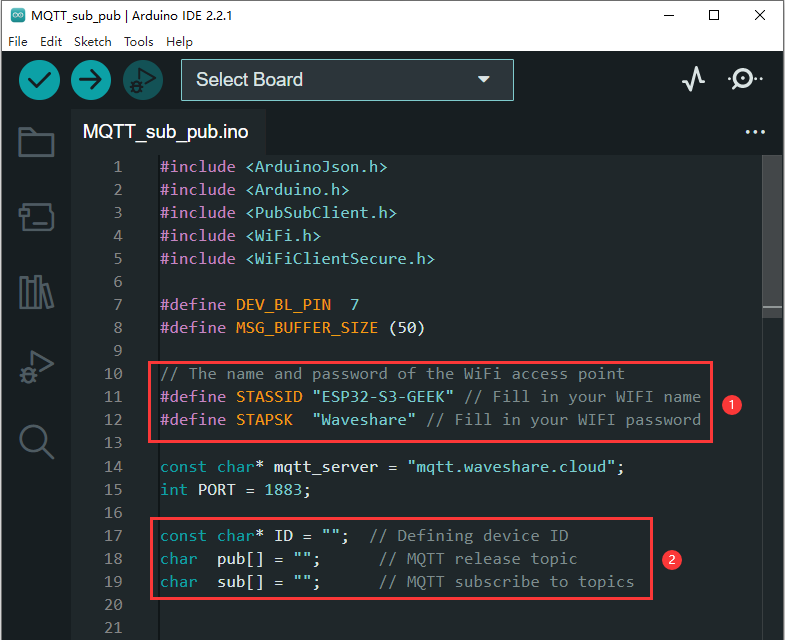
- In the callback function, you can modify the identification tag to our device attribute identifier created on the cloud platform
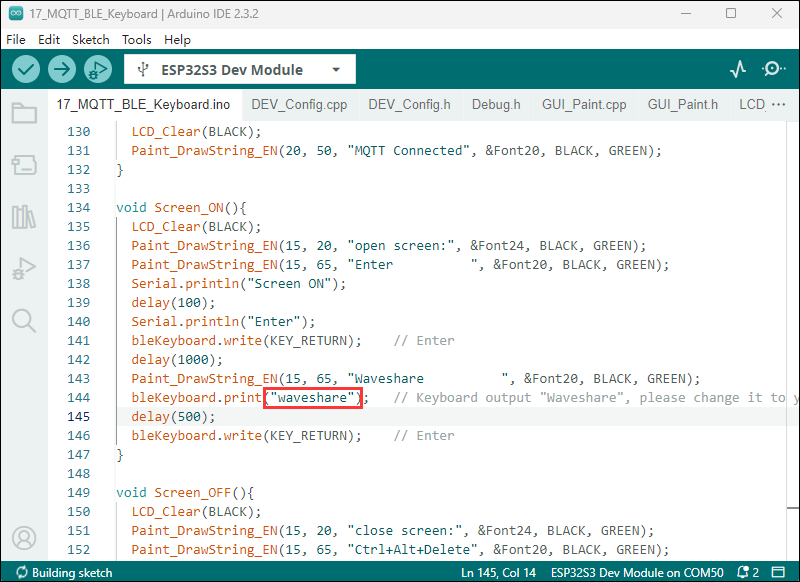
- Modify it to your own screen unlock password
Code flashing
- Select the development board model ESP32S3 Dev Module and port
- Flash the code
Result demonstration
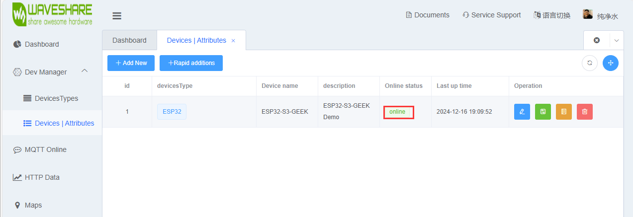
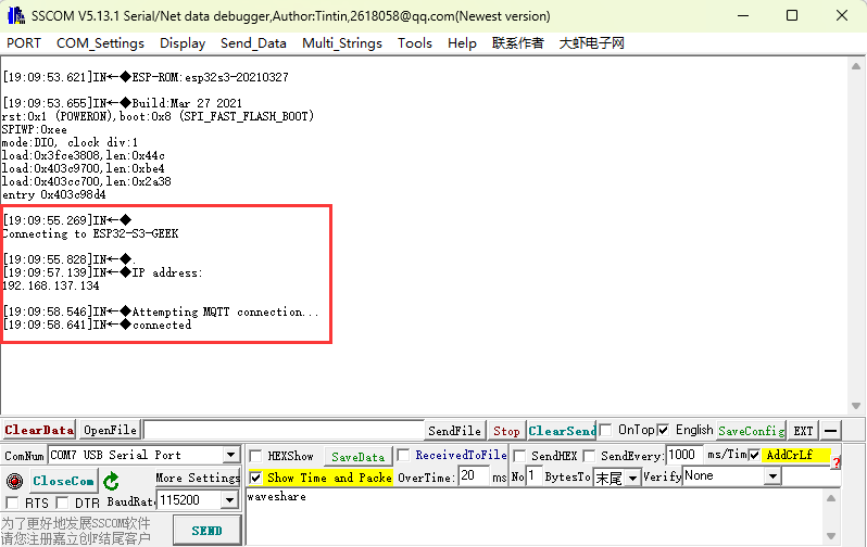
- After flashing the code, once the Wi-Fi connection is established, observe whether the device goes online on the Microsnow Cloud platform. If it does not, you can try refreshing the web page or use a USB-to-UART connection to the PC to check the Wi-Fi and MQTT connection status via a serial port debugging assistant. The LCD screen will also display the connection status of Wi-Fi and MQTT
- After the ESP32-S3-GEEK connects to the Waveshare Cloud, you can log in to the Waveshare Cloud Dashboard on your phone remotely lock the PC screen, and input a password for screen unlocking.
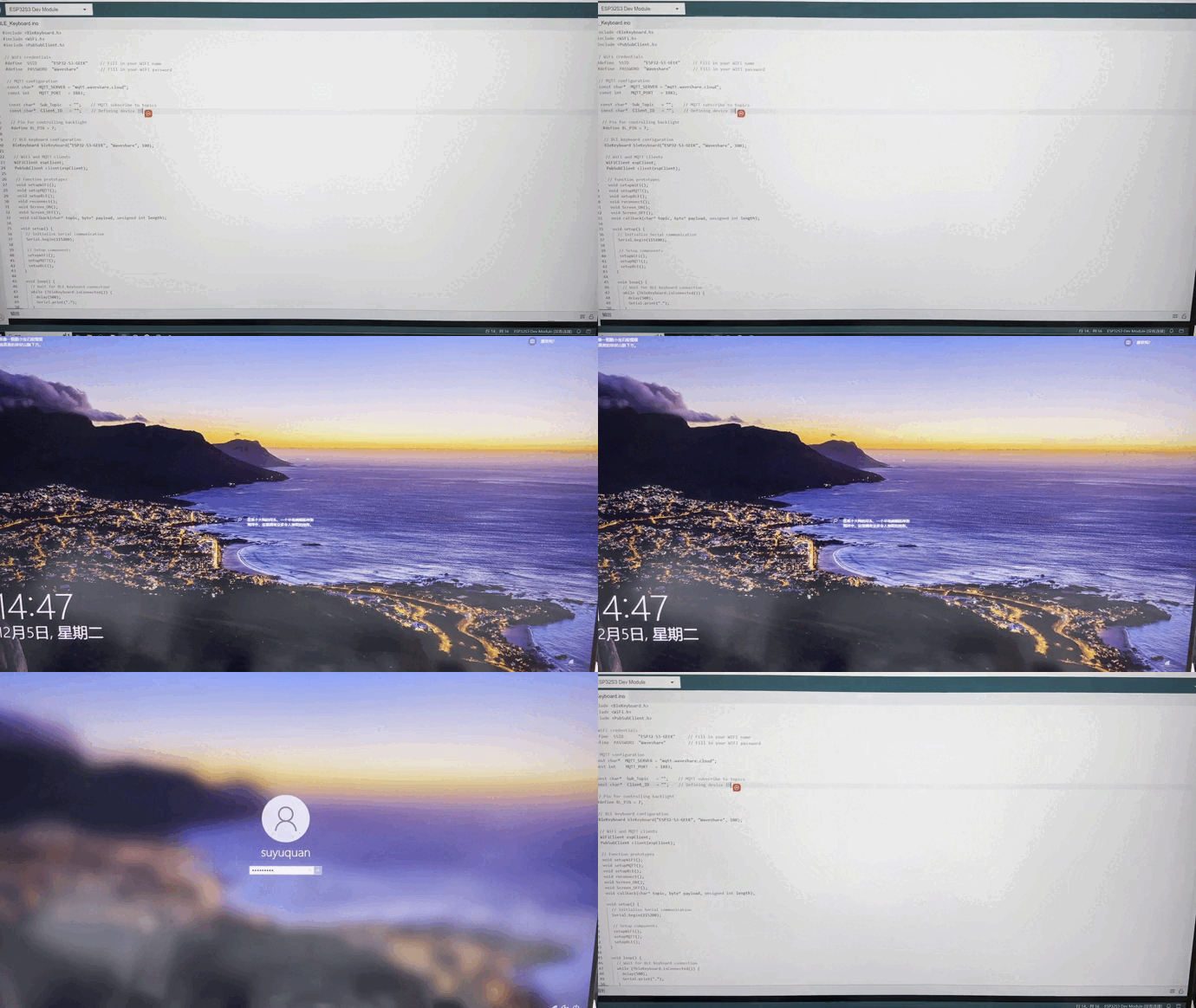
- We can observe different feedback regarding changes in device attribute values (e.g., "key") on both the LCD and the serial debugging assistant. Additionally, we can further customize the callback function to modify keys into combinations like Ctrl+C, and Ctrl+V, allowing for a personalized DIY remote-controlled Bluetooth keyboard.

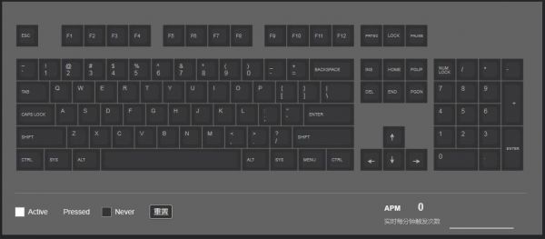
- Or you can enter keyboard tester website to test the keys remotely pressed by the ESP32-S3-GEEK Bluetooth.
Install Driver
- Before using the module, you need to prepare the following things except Type C USB cable, GNSS antenna and LTE antenna:
a 4G SIM card (GPRS is available)
- In case of power failure, insert the activated 4G SIM card, and connect the USB cable to the computer.
- Connect one end of the Type C USB cable to the PC's USB port and the other end to the USB port of the ESP32-SIM7670G . The PWR light will illuminate, and wait approximately 0 to 1 second for the module to start. The NET light will remain steady, indicating successful module startup. Wait for the module to automatically search for the network; the NET light will begin to flash.
- Open the device manager; for first-time use, install the Windows driver. Refer to the following image for installation instructions:
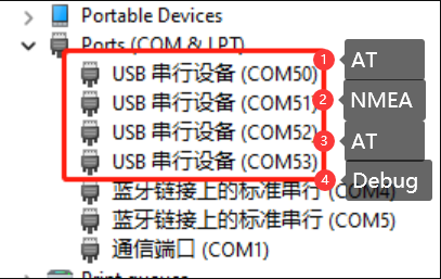
- After the driver is successfully installed, you can see more COM ports as shown below:
Working with ESP-IDF
This chapter introduces the setup of the ESP-IDF environment, including the installation of Visual Studio, the Espressif IDF plugin, program compilation and download, as well as testing of sample programs. It aims to help users gain proficiency with the development board for secondary development.
Environment Setup
Download and Install VSCode
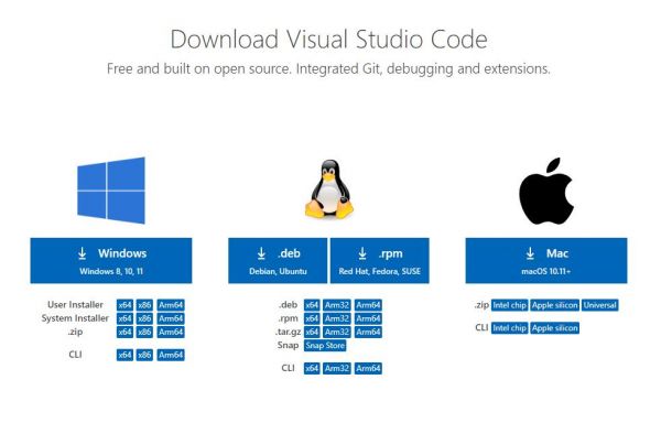
- Open the download page of the official VSCode website, and select the corresponding system and system bit to download.
- After running the installation package, the rest can be installed by default, but here for the subsequent experience, it is recommended to check boxes 1, 2, and 3
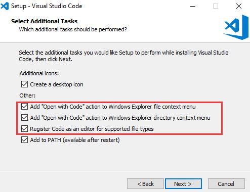
- After the first and second items are enabled, you can open VSCode directly by right-clicking files or directories, which can improve the subsequent user experience.
- After the third item is enabled, you can select VSCode directly when you choose how to open it.
Install Espressif IDF Plugin
- The "online installation" is generally recommended for installing the Espressif IDF plugin. If online installation is not possible due to network issues, then "offline installation" can be used.
- For the tutorial on installing the Espressif IDF plugin, please refer to: Install Espressif IDF Plugin Tutorial
Run the First ESP-IDF Demo
New Project
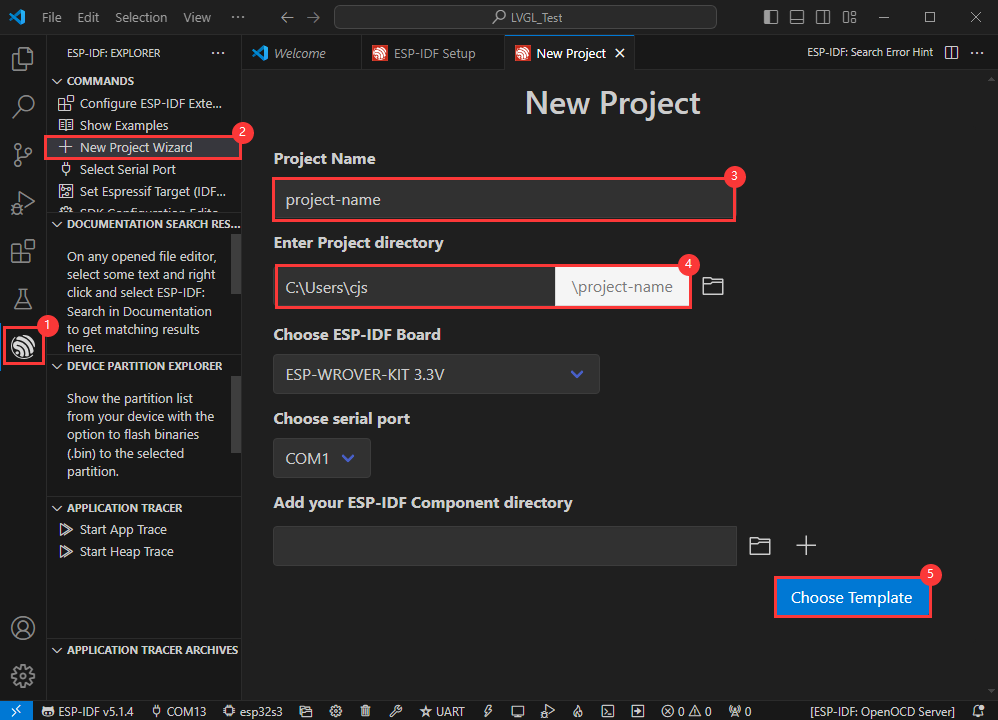
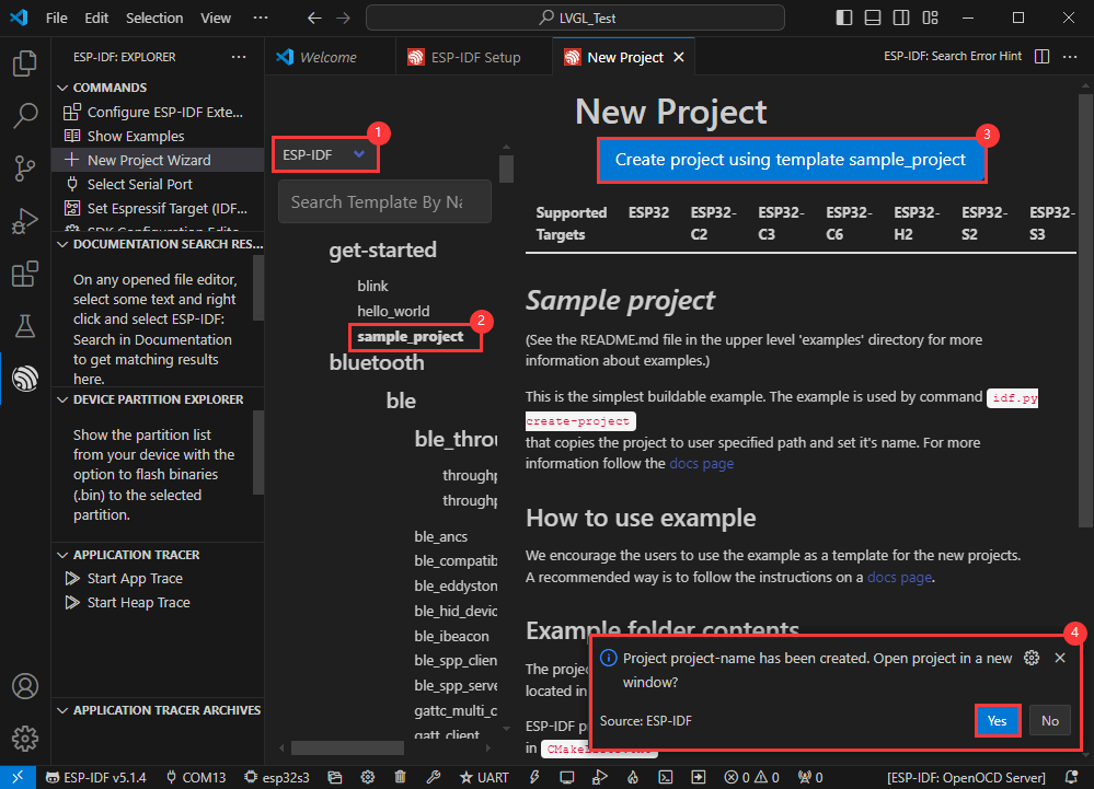
Create Demo
- Using the shortcut F1, enter esp-idf:show examples projects
- Select your current IDF version

- Take the Hello world demo as an example
①Select the corresponding demo
②Its readme will state what chip the demo applies to (how to use the demo and the file structure are described below, omitted here)
③Click to create the demo
- Select the path to save the demo, and require that the demos cannot use folders with the same name

Modify COM port
- The corresponding COM ports are shown here, click to modify them
- Please select the COM ports according to your device (You can view it from the device manager)
- In case of a download failure, please press the Reset button for more than 1 second or enter download mode, and wait for the PC to recognize the device again before downloading once more

Modify driver object
- Select the object we need to drive, which is our main chip ESP32S3

- Choose the path to openocd, it doesn't affect us here, so let's just choose one

Introduction to other status bar functions
①.ESP-IDF Development Environment Version Manager, when our project requires differentiation of development environment versions, it can be managed by installing different versions of ESP-IDF. When the project uses a specific version, it can be switched to by utilizing it
②.Device flashing COM port, select to flash the compiled program into the chip
③.Select set-target chip model, select the corresponding chip model, for example, ESP32-P4-NANO needs to choose esp32p4 as the target chip
④.menuconfig, click it to modify sdkconfig configuration file, please refer to project configuration details
⑤.fullclean button, when the project compilation error or other operations pollute the compiled content, you can clean up all the compiled content by clicking it
⑥.Build project, when a project satisfies the build, click this button to compile
⑦.Current download mode, the default is UART
⑧.flash button, when a project build is completed, select the COM port of the corresponding development board, and click this button to flash the compiled firmware to the chip
⑨.monitor enable flashing port monitoring, when a project passes through Build --> Flash, click this button to view the log of output from flashing port and debugging port, so as to observe whether the application works normally
⑩.Debug
⑪.Build Flash Monitor one-click button, which is used to continuously execute Build --> Flash --> Monitor, often referred to as “little flame”
Compile, flash and serial port monitor
- Click on the all-in-one button we described before to compile, flash and open the serial port monitor.

- It may take a long time to compile especially for the first time

- During this process, the ESP-IDF may take up a lot of CPU resources, so it may cause the system to lag
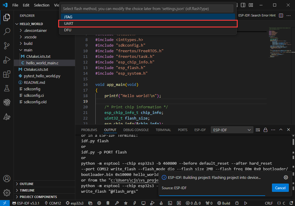
- If it is the first time to flash the program for a new project, you will need to select the download method, and select UART

- This can also be changed later in the Download methods section (click on it to pop up the options)

- As it comes with the onboard automatic download circuit, it can be downloaded automatically without manual operation
- After successful download, it will automatically enter the serial monitor, you can see the chip output the corresponding information and be prompted to restart after 10S

Use the IDF demos
Open in the software
- Open VScode software and select the folder to open the demo

- Select the provided ESP-IDF example and click to select the file (located in the Examples/Demo/ESP-IDF path)

Open from outside the software
- Select the project directory correctly and open the project, otherwise it will affect the compilation and flashing of subsequent programs

- After connecting the device, select the COM port and model, click below to compile and flash to achieve program control

ESP-IDF Project Details
- Component: The components in ESP-IDF are the basic modules for building applications, each component is usually a relatively independent code base or library, which can implement specific functions or services, and can be reused by applications or other components, similar to the definition of libraries in Python development.
- Component reference: The import of libraries in the Python development environment only requires to "import library name or path", while ESP-IDF is based on the C language, and the importing of libraries is configured and defined through
CMakeLists.txt. - The purpose of CmakeLists.txt: When compiling ESP-IDF, the build tool
CMakefirst reads the content of the top-levelCMakeLists.txtin the project directory to read the build rules and identify the content to be compiled. When the required components and demos are imported into theCMakeLists.txt, the compilation toolCMakewill import each content that needs to be compiled according to the index. The compilation process is as follows:
- Component reference: The import of libraries in the Python development environment only requires to "import library name or path", while ESP-IDF is based on the C language, and the importing of libraries is configured and defined through

Demo
| Demo | Basic Description |
|---|---|
| Wireless_USB_flash_drive | The ESP32-S3-GEEK can be used as a USB disk with wireless access capabilities |
Wireless_USB_flash_drive
Program Description
- This routine allows the ESP32-S3-GEEK to be used as a USB disk with wireless access capabilities. When combined with SD card storage, it can become a high-capacity wireless storage device. Additionally, you can connect to the ESP32-S3-GEEK's hotspot to upload and download via an HTTP file server, greatly facilitating user operations. It is suitable for learning the USB MSC functionality of the ESP32, as it can act as a storage device connected to a USB host, supporting various storage methods, with callback functions to handle various events, and testing for stability and reliability
- To exit the program, simply press the boot button and power cycle the device
Hardware connection
- Insert the TF card into the development board
- Connect the development board to the computer
Code analysis
- init_fat():Initializes the FAT file system. Depending on the configuration, it mounts either the internal flash memory or an external TF card
- If using internal flash memory, a specific function is selected for mounting based on the ESP-IDF version
- If using an external TF card, it is initialized and mounted according to the interface type (SPI or SDIO)
- app_main ():The main function that coordinates the initialization of various parts of the program, including file storage, Wi-Fi (if configured), and USB MSC
- Calls
init_fatto initialize file storage - If Wi-Fi is configured, it initializes and starts the file server
- Initializes tinyUSB and installs the driver
- Calls
Code flashing
- Ensure the TF card is installed
- Select the model (esp32s3) and port
- Download via UART
- Flash the program
Result demonstration
- After programming, unplug and plug the ESP32-S3-GEEK again, and you can see a new USB flash driver
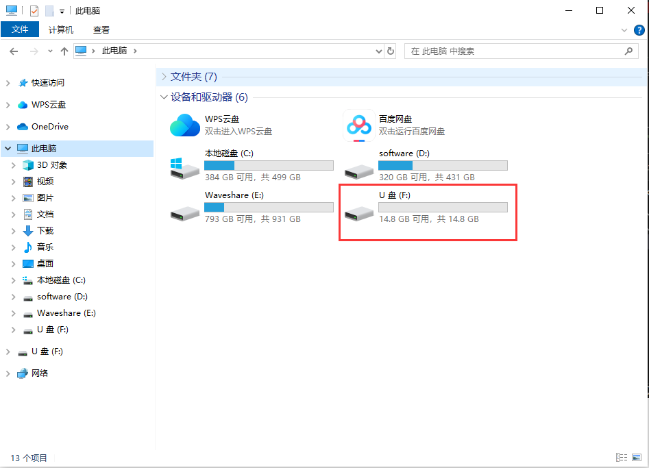
- You can open the USB drive to browse through the files on the TF card and perform various operations such as adding, deleting, modifying, and checking files
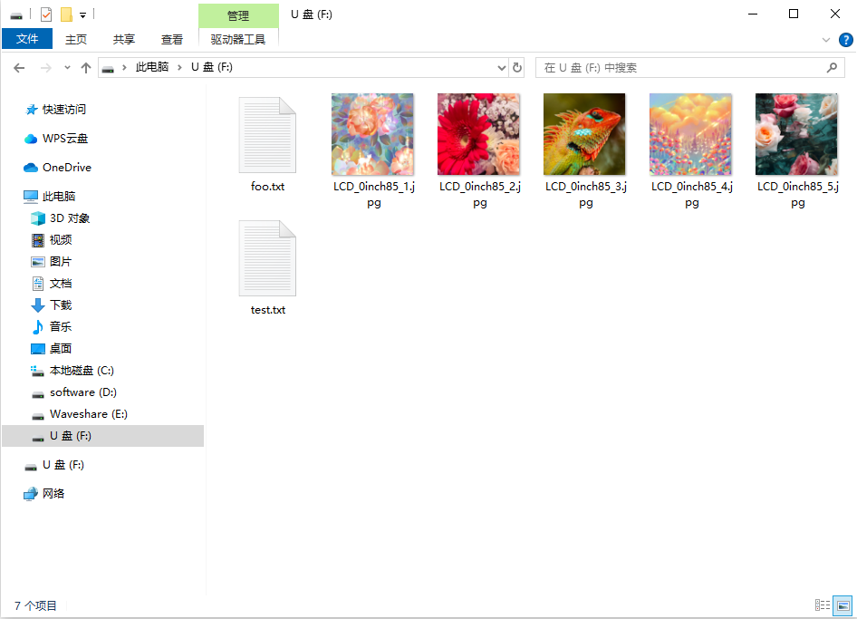
- Enter the PC's WIFI setting, connect to the ESP32-S3-GEEK's AP, and input the password of "Waveshare"
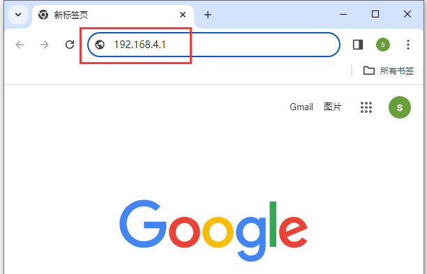
- After connecting successfully, open the browser, and log in to IP: 192.168.4.1
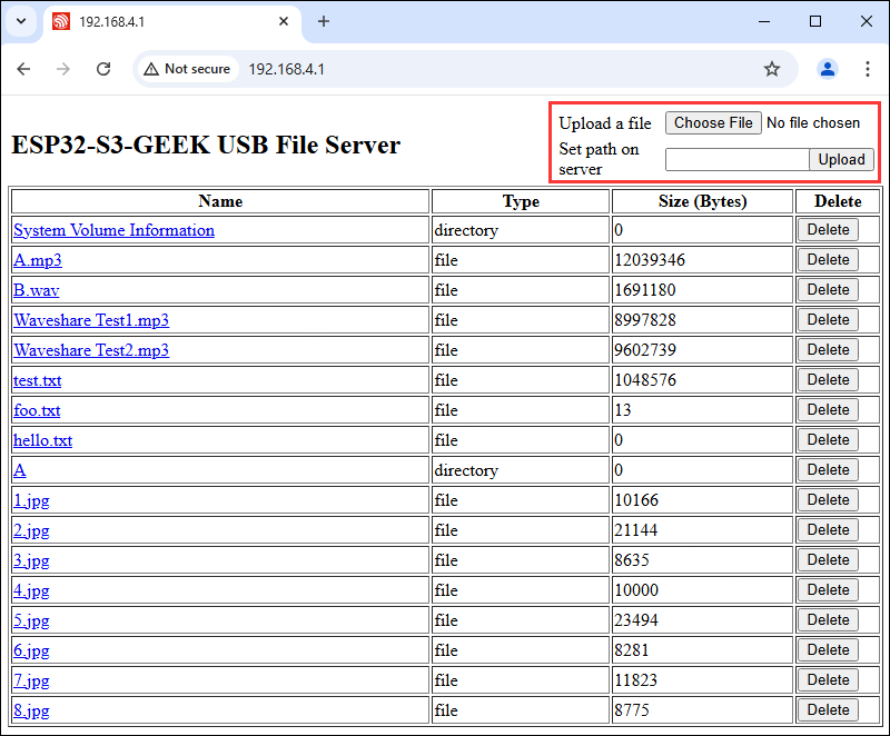
- After login successfully, you can upload and download files wirelessly
Working with MicroPython
This section focuses on setting up the MicroPython development environment, primarily covering firmware flashing, installation, and the use of Thonny. For the installation part of Thonny, detailed explanations of the installation steps and usage instructions are provided, offering comprehensive and clear guidance for developers to build a MicroPython development environment.
Environment Setup
Download and install Thonny
- Open the download page of Thonny official website and select the corresponding system and system bit to download
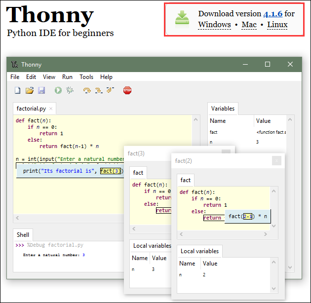
- Select the appropriate system and version, for example, with a 64-bit Windows, the mouse needs to be moved to the Windows section to display the corresponding information, then click to Download and Install
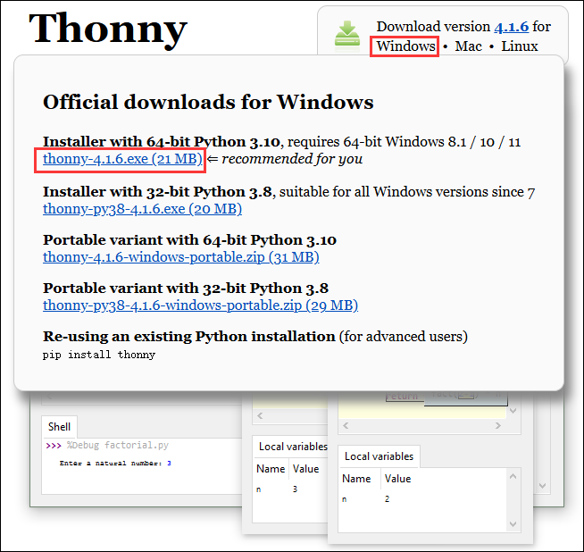
- The rest can be installed by default
Flash the firmware
- Currently, the development board is developed using customized firmware, which is available in ESP32-S3-GEEK demo, the firmware is merged into a single file, note that the download address is the 0x00 location
- Firmware path:
...\ESP32-S3-GEEK-Demo\Firmware\MicroPython-bin
- For a tutorial on flashing firmware, please refer to Flash Firmware Flashing and Erasing tutorial
- The bin file in the factory-bin folder is a file for testing the onboard function, and there is no need to flash it here
Thonny Usage
Select the development board and model
- Download and install the latest Thonny IDE, then open Thonny IDE -> Configure interpreter..., as shown in the following image
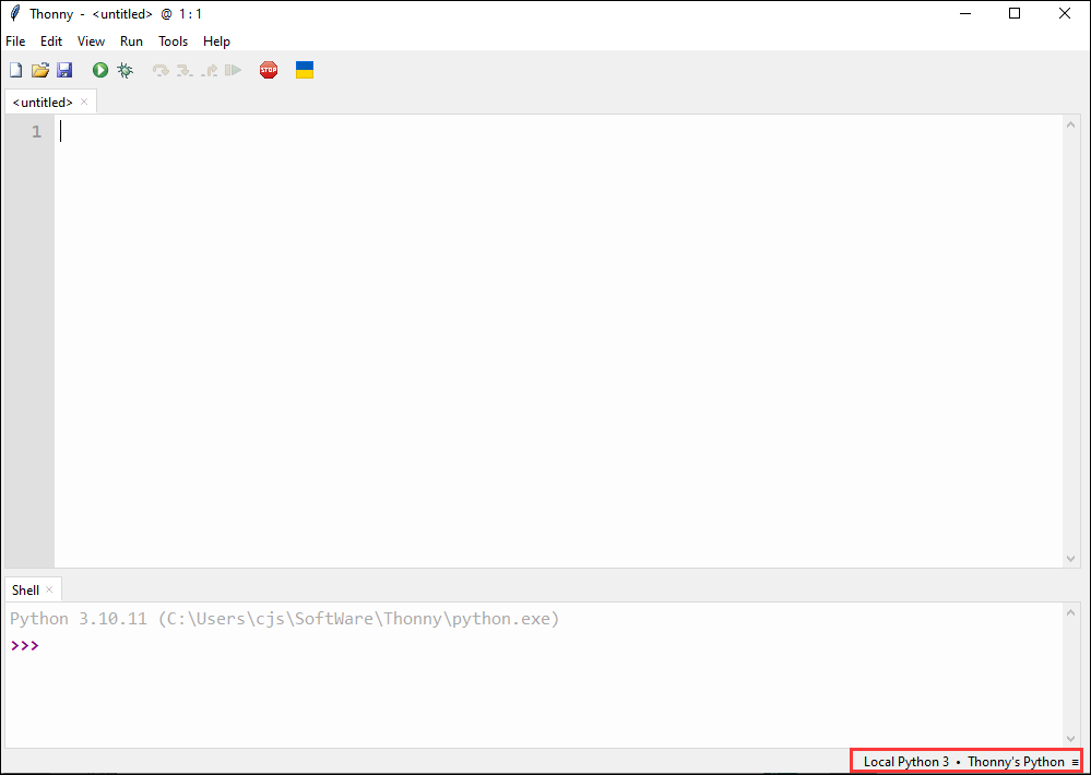
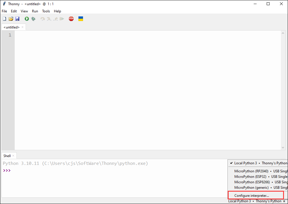
- Select ESP32 and the corresponding COM port
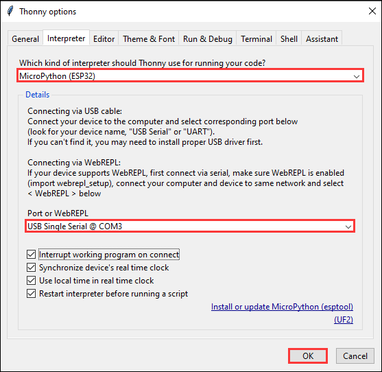
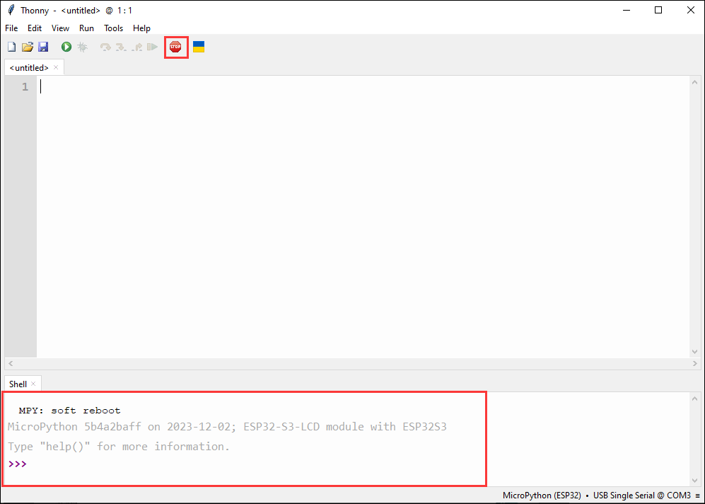
- Click this button to see the output statement in the shell, which indicates that the development board firmware has been successfully utilized
Upload demo
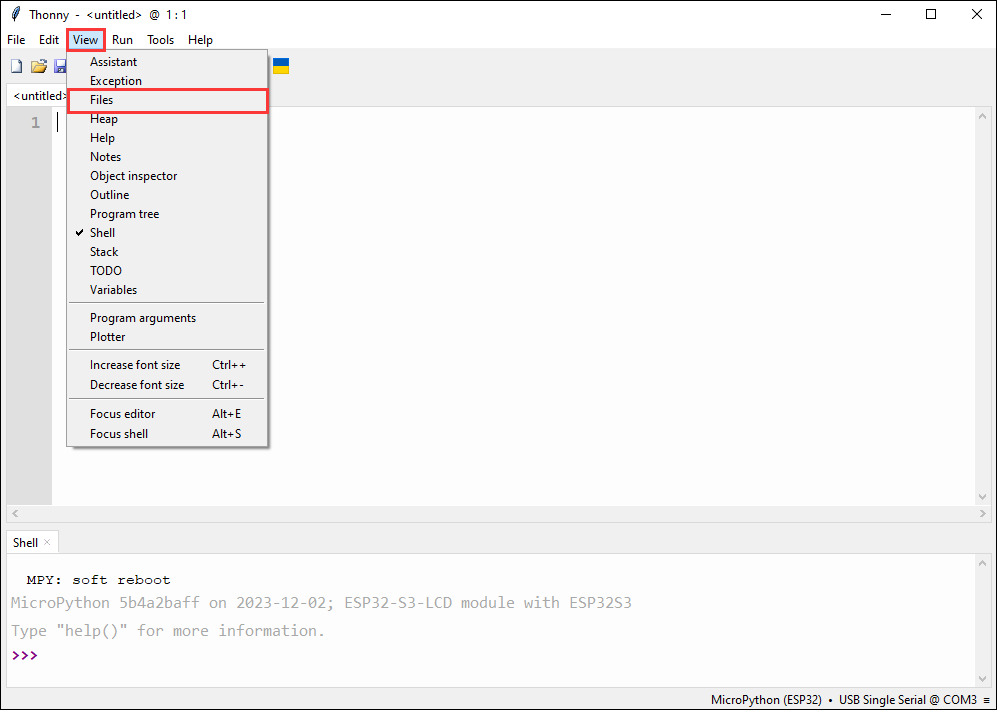
- How to find the desired demo, if there is no Files column at the beginning, we can find it in the View
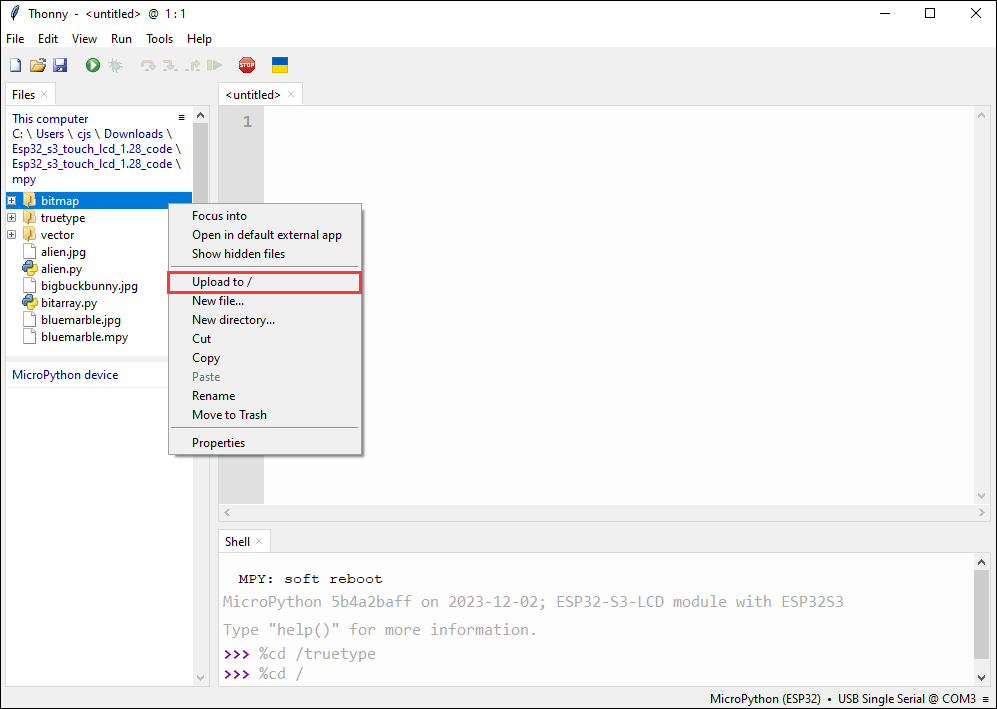
- Upload the local file to the development board, select the file, right-click with the mouse, find "Upload to/", and then download
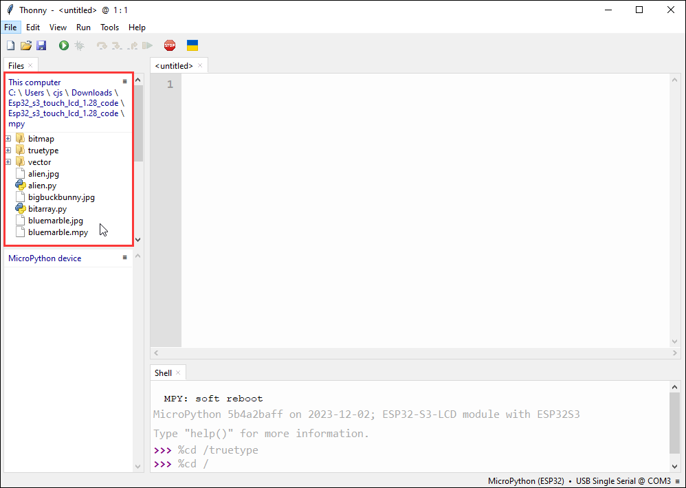
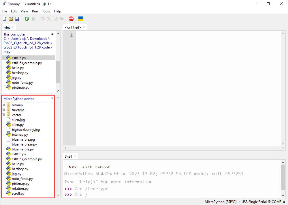
- The following is the interface where all downloads are completed, the downloaded file must be consistent with the file in the red box, otherwise it may fail to run
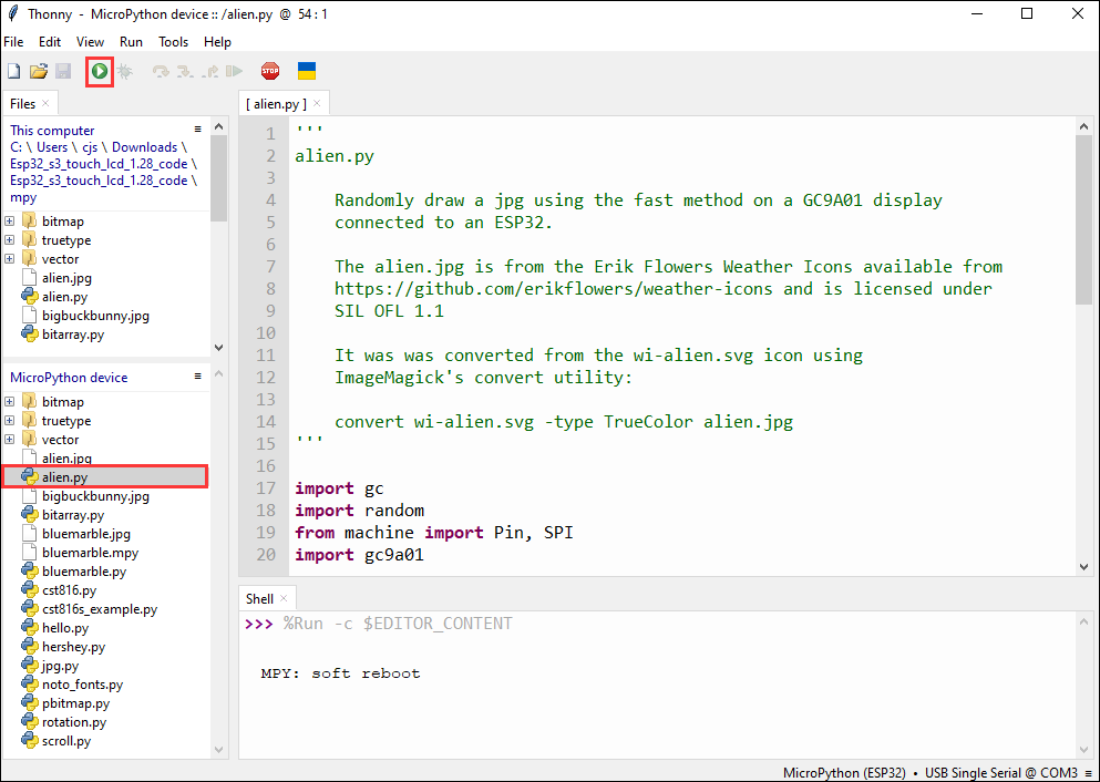
- Select the file with the .py suffix, and click the green button to flash and run
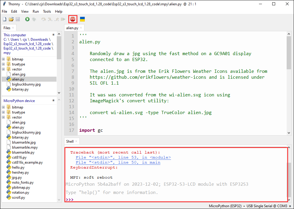
- When running another file, first click the red stop button, so that the other file can run normally
Demo

| Demo | Basic Description |
|---|---|
| lcd_example.py | Uses the ESP32-S3-GEEK to turn on the LCD screen, display text information, and show BMP images |
| Uart0.py | Serial communication |
| WS_Bluetooth.py | Enables the Bluetooth on the ESP32-S3-GEEK and uses Bluetooth to communicate with a mobile phone's Bluetooth debugging assistant |
| WIFI_AP.py | Turns on the WiFi Access Point (AP) mode, allowing a PC to connect to its WiFi |
| WIFI_STA.py | Turns on the WiFi Station (STA) mode, allowing it to connect to a hotspot opened by a PC or other WiFi networks |
Upload demo and special demos
Upload demo
- Upload the local file to the development board, select the file, right-click with the mouse, find "Upload to/", and then download
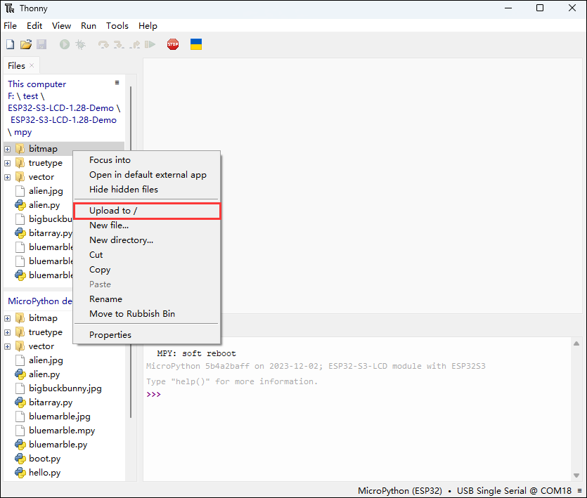
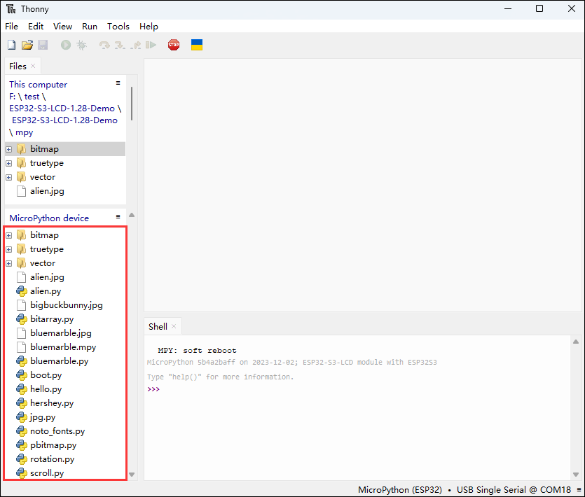
- The following is the interface where all downloads are completed, the downloaded file must be consistent with the file in the red box, otherwise it may fail to run
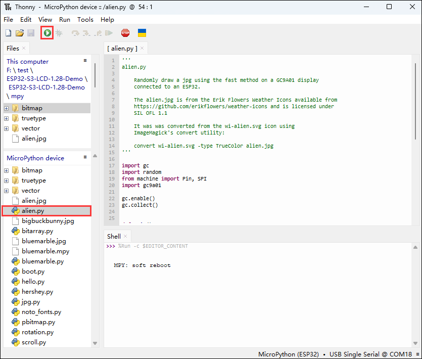
- Select the file with the .py suffix, and click the green button to flash and run (the operation figure is as follows)
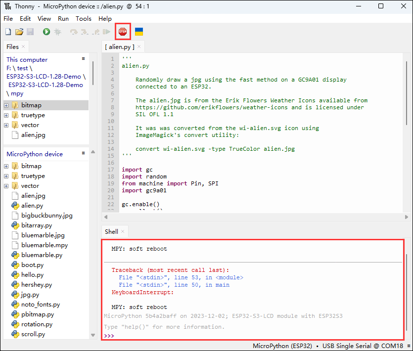
- When running another file, first click the red stop button, so that the other file can run normally
LCD
Program Description
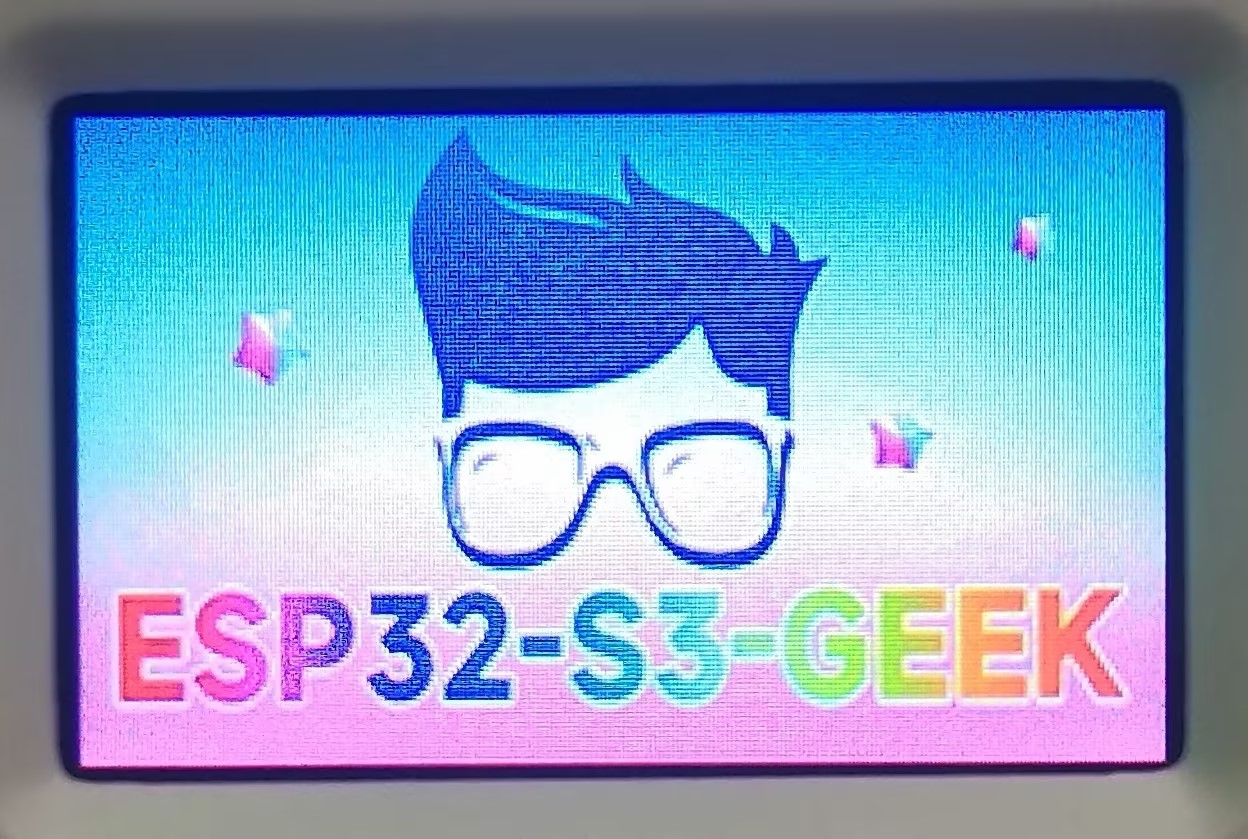
- This routine can use the ESP32-S3-GEEK to turn on the LCD screen, display text information, and show BMP images
- To run, please execute lcd_example.py
Hardware connection
- Connect the development board to the computer
Code analysis
- lcd_example.py mainly defines a class
LCD_1inch14for controlling a LCD display of a specific size. It includes functions such as initializing the display hardware, sending commands and data to the display, operating on the display buffer, and displaying images and text.- First, a
BMPReaderobjectimgis created, and a BMP image file path'./ESP32-S3-GEEK.bmp'is passed to it. This calls the constructor of theBMPReaderclass defined in the second section of the code, which in turn calls the_read_img_infomethod to read the relevant information of the image file. - Then, through a loop, the
img.get_buf(270, 270*x)method is called to read data of a specific length from the BMP image and insert it into the LCD's frame buffer (implemented by calling theinsmethod of theLCD_1inch14class in the first section of the code). The parametersdata_lenandstartof the get_buf method are used to control the length of the data read and the starting position, ensuring that the data is correctly extracted from the BMP image and displayed on the LCD.
- First, a
- bmp_reader.py defines a BMPReader class for reading BMP image files. It can parse specific information from BMP files and extract data of a specific position and length from the file, converting it into a byte array of a specific format (RGB565) and returning it
Result demonstration
- LCD screen display
SD
Program Description
- This routine can read the TF card slot of the ESP32-S3-GEEK, and you can directly open the sd folder of the ESP32-S3-GEEK to browse the files on the TF card. Before use, you need to insert the TF card into the slot first. It is suitable for interaction between ESP32 and TF cards, initializing the TF card, and mounting the file system to test stability and reliability
Hardware connection
- Connect the development board to the computer
- Insert the TF card into the development board
Code analysis
- boot.py:
- Connects to the TF card by setting the Chip Select (CS) pin and initializing the SPI bus
- Creates an instance of
sdcard.SDCardand mounts it to the file system usinguos.mount(sd, '/sd'). Once mounted successfully, you can use file system operations likeos.listdir('/sd')to view the contents of the TF card, traverse files and directories, and read file contents, etc.
- sd_card.py
- Defines the TFCard class, which provides methods for interacting with the TF card, initializing the TF card, sending commands, reading and writing data blocks, etc.
- This code does not have the functionality to directly display the contents of the TF card, but it provides a low-level operation interface for higher-level code. Through these interfaces, it is possible to read files from the TF card and display their contents, such as reading the content of a specific file and printing it out
- The two segments of code work together to achieve access to and display of content on the TF card in a MicroPython environment. The first segment of code is usually the part used by the user, which completes specific tasks by calling the functions implemented in the second segment of code
Result demonstration
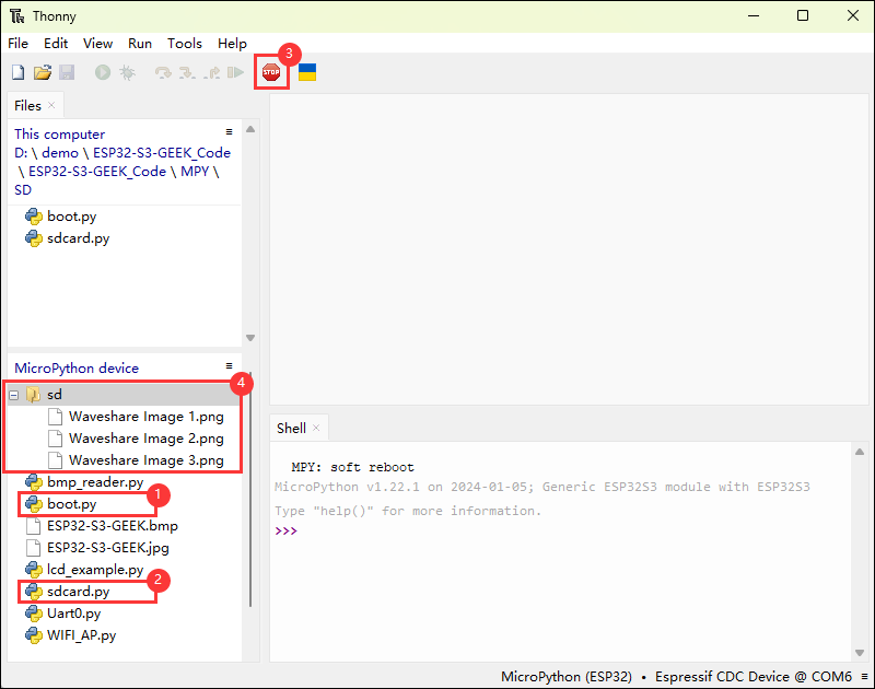
- ①②.Ensure that two folders have been uploaded to the development board
- ③.Clicking stop allows you to see that an sd folder has appeared on the device
- ④.The contents of the sd folder are the contents of the inserted TF card
Uart0.py
Program Description
- This routine allows the use of the ESP32-S3-GEEK to open UART0, and with the help of a serial port debugging assistant, serial communication can be conducted. It is suitable for interaction between MicroPython and UART, initializing UART, and testing the stability and reliability of data transmission and reception
Hardware connection
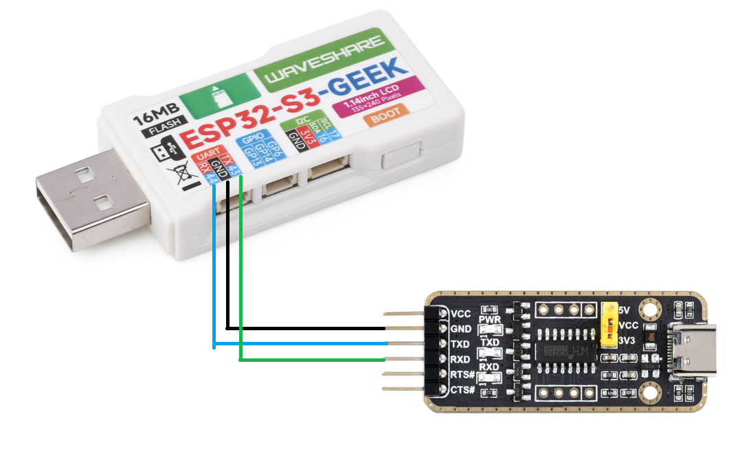
- Connect the development board to the computer
- It is possible to connect devices such as USB-to-UART modules for serial communication
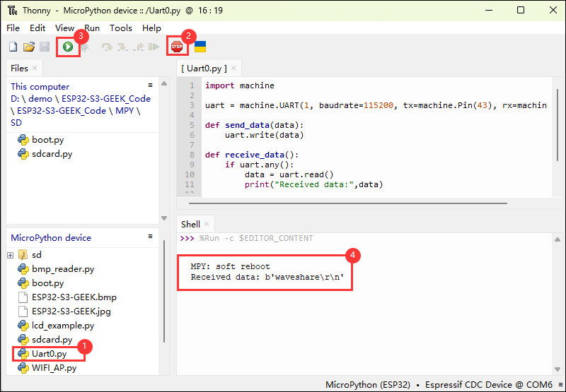
Code analysis
- Module Import and UART Initialization
import machine: Imports themachinemodule of MicroPython, which is used to control hardware resources- Create a UART object
uart, specifying the use of UART1, setting the baud rate to 115200, and configuring the UART hardware connection by designating the transmit pin asmachine.Pin(43)and the receive pin asmachine.Pin(44)
- Function Definitions
send_datafunction: Accepts a data parameter and uses the UART's write method to send datareceive_datafunction: Checks if there is readable data on the UART, and if there is, it reads the data and prints it out
Result demonstration
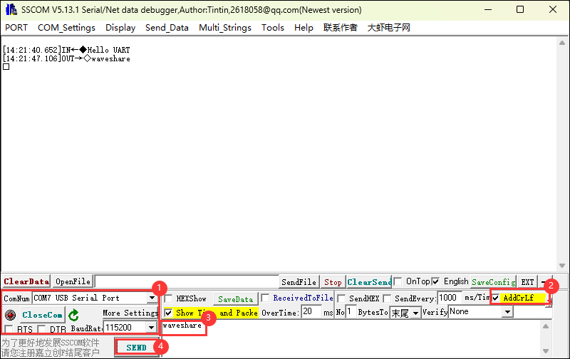
- After running,send the string "Hello UART"
- Using a serial port debugging assistant for communication testing
WS_Bluetooth.py
Program Description
- This routine enables the Bluetooth functionality of the ESP32-S3-GEEK, allowing communication with a mobile phone's Bluetooth debugging assistant
Hardware connection
- Connect the development board to the computer
Code analysis
- ble_irq: A Bluetooth interrupt handling function that processes events accordingly
- If the event is a connection (event value is 1), the
connectedfunction is called - If the event is a disconnection (event value is 2), the
disconnectedfunction is called - If the event is data reception (event value is 3), the received characteristic value is read and printed
- If the event is a connection (event value is 1), the
- advertiser
- Converts the device name into a byte array and constructs the advertising data
- Uses the Bluetooth instance's
gap_advertisemethod to broadcast
- Bluetooth_Init
- Initializes the Bluetooth device
- Creates a Bluetooth instance, activates Bluetooth, sets the device name, registers the interrupt handling function, registers services, and broadcasts device information
Result demonstration
- After the program runs, it prints the model of the development board
- It is suitable for communication with a mobile phone's Bluetooth debugging assistant


WIFI_AP.py
Program Description
- This routine allows the ESP32-S3-GEEK to open WIFI in AP (Access Point) mode, enabling a PC to connect to its WIFI. It is suitable for creating a Wi-Fi access point with the ESP32-S3-GEEK under MicroPython and testing its stability and reliability
Hardware connection
- Connect the development board to the computer
Code analysis
- redian
- Creates a Wi-Fi (Access Point,AP) object
apusingnetwork.WLAN(network.AP_IF), which creates a network interface based on AP mode - Activates the access point with
ap.active(True), causing the device to start working as a Wi-Fi hotspot - Configures the access point's parameters with
ap.config, including the network name (ESSID) set to 'ESP32-S3-GEEK', the authentication mode set tonetwork.AUTH_WPA_WPA2_PSK(WPA/WPA2-PSK encryption), and the password set to 'Waveshare' - Prints the IP address of the access point by obtaining it with
ap.ifconfig()[0]and displaying it
- Creates a Wi-Fi (Access Point,AP) object
Result demonstration
- After the code runs, it prints the IP address of the access point
- You can use a PC to open a wifi connection, with the WiFi name: ESP32-S3-GEEK, and the password: waveshare

WIFI_STA.py
Program Description
- This routine allows the ESP32-S3-GEEK to open WIFI in STA (Station) mode, enabling it to connect to a hotspot opened by a PC or other WIFI networks. It is suitable for connecting the ESP32 to a specific Wi-Fi network under MicroPython and testing its stability and reliability
Hardware connection
- Connect the development board to the computer
Code analysis
- do_connect: The main entry point of the program, which initializes the display and shows the names of three font types
- Creates a Wi-Fi client interface object
wlanusingnetwork.WLAN(network.STA_IF), establishing a network interface based on station mode
- Creates a Wi-Fi client interface object
Activates the Wi-Fi interface with wlan.active(True), allowing the device to connect to an external Wi-Fi network If the device is not currently connected to a network, it prints a "connecting to network" message and attempts to connect to the specified Wi-Fi network, with the SSID being "ESP32-S3-GEEK" and the password "Waveshare" Continuously checks for a successful connection in a loop until wlan.isconnected() returns True Once connected, it prints the current network configuration information, including IP address, subnet mask, gateway address, etc., obtained and printed through wlan.ifconfig()
Result demonstration
- You can open a hotspot on your PC with the SSID and password: "ESP32-S3-GEEK", "Waveshare"
- After the program runs and connects to Wi-Fi, it prints the current network configuration information

Flashing and Erasing Firmware
- The current example program provides a test firmware that can be used to verify the functionality of the board by flashing the test firmware directly
- bin file path:
..\ESP32-S3-GEEK-Demo\Firmware\factory-bin
Resources
Schematic
Demo
Datasheets
ESP32-S3
Additional Devices
Software
Arduino
VScode
Thonny
Debugging Tool
- sscom serial port assistant
- NetAssist tool
- IOS Bluetooth assistant
- Android Bluetooth debugging tool
- Android TCP debugging tool
Firmware Flashing Tool
Additional Resource Links
- ESP32-Arduino Official Document
- ESP32-Arduino Official Resource
- ESP-IDF Official Document
- MicroPython Official Document
FAQ
Question:ESP32-S3-GEEK programming failed?
① During programming, long-press the Boot button, insert the USB, and then release the button to enter the ESP32-S3-GEEK Download mode for the programming process. After programming, reconnecting the USB will enter the SPI_FAST_FLASH_BOOT mode, run the demo.
② Try turning off the PC's Bluetooth switch and then directly flash and run (indicating the conflict between the Bluetooth driver and the ESP32-S3-GEEK's COM driver results in the programming failure).
Question:What to do if the program's first compilation is extremely slow?
- The slowness of the first compilation is a normal occurrence; you just need to wait patiently.
Question:What to do if you can't find the AppData folder?
- Some AppData folders are hidden by default and can be set to be visible.
- For English systems: File Explorer > View > Check "Hidden items"
- For Chinese systems: File Explorer > View > Show > Check "Hidden items"
Question:How to check which COM port you are using?
- Windows System:
①Check via Device Manager: Press Windows + R to open the "Run" dialog box; enter devmgmt.msc and press Enter to open Device Manager; expand the "Ports (COM and LPT)" section, which will list all COM ports and their current status.
②Use Command Prompt to check: Open Command Prompt (CMD); enter the mode command, which will display the status information of all COM ports.
③Check hardware connections: If you have connected an external device to a COM port, the device will typically occupy a port number, and you can determine which port is being used by examining the connected hardware.
- Linux System:
①Use the dmesg command to check: Open the terminal.
②Use the ls command to check: Enter ls /dev/ttyS* or ls /dev/ttyUSB* to list all serial devices.
③Use the setserial command to check: Enter setserial -g /dev/ttyS* to view the configuration information of all serial devices.
- Re-flash after installing the MAC driver.
Question:ESP32-S3-GEEK successfully connected to Waveshare Cloud, why can't it send or receive MQTT messages?
Please check if the Pub Topic and Sub Topic are correctly filled in, and verify if the device is online in the Waveshare Cloud. Both factors could impact the ability to send or receive MQTT messages.
Question:When the SD card is inserted into the ESP32-S3-GEEK, can the computer directly function as a USB flash driver? After inserting the SD card, can you directly view its files using Windows File Explorer when connected to the computer?
Yes, you need to flash #Wireless_USB_flash_drive, in the SD card image, SPIFS only supports up to 32GB.
Question:What is the model of the LCD driver chip for the ESP32-S3-GEEK?
The driver chip for the 1.14LCD is the ST7789P3.
Question:ESP32-S3-GEEK flashed the Wireless_USB_flash_drive demo, and the 16G MicroSD card is inserted into the SD card slot, but the display memory is only 1.4M?
- 1. Click Settings in the lower left corner.

- 2. Modified "Use Internal Flash" to "Use External SDCard".


- 3. Save the settings and flash again.

Question:Why is there no output after successfully flashing the code with no issues?
- Check the schematic diagram. Different development boards have different handling of the Type-C interface, which corresponds to different code output handling:
- For development boards with direct USB output, printf function is supported for printing output. If you want to support output via the Serial function, you need to enable the USB CDC On Boot feature or declare HWCDC.
- For development boards with UART-to-USB conversion, both printf and Serial functions are supported for printing output, and there is no need to enable USB CDC On Boot.
Support
Monday-Friday (9:30-6:30) Saturday (9:30-5:30)
Email: services01@spotpear.com
[Tutorial Navigation]
- Overview
- Usage instructions
- Working with Arduino
- Environment setup
- Run the First Arduino Demo
- Demos
- 01_OneButton
- 02_ADC_Read
- 03_IIC_BME68X_Sensor
- 04_UART0
- 05_LCD_Button
- 06_LCD_Time
- 07_SD_Test
- 08_SD_LCD
- 09_BLE_LCD
- 10_BLE_UART
- 11_BLE_Keyboard
- 12_WIFI_AP_LCD
- 13_WIFI_TCP_Client
- 14_WIFI_TCP_Server
- 15_WIFI_Web_Server
- 16_MQTT_sub_pub
- 17_MQTT_BLE_Keyboard
- Install Driver
- Working with ESP-IDF
- Environment Setup
- Run the First ESP-IDF Demo
- New Project
- Create Demo
- Modify COM port
- Modify driver object
- Introduction to other status bar functions
- Compile, flash and serial port monitor
- Use the IDF demos
- Demo
- Working with MicroPython
- Flashing and Erasing Firmware
- Resources
- FAQ
- Question:ESP32-S3-GEEK programming failed?
- Question:What to do if the program's first compilation is extremely slow?
- Question:What to do if you can't find the AppData folder?
- Question:How to check which COM port you are using?
- Question:What to do if the program flashing fails when using a MAC device?
- Question:ESP32-S3-GEEK successfully connected to Waveshare Cloud, why can't it send or receive MQTT messages?
- Question:When the SD card is inserted into the ESP32-S3-GEEK, can the computer directly function as a USB flash driver? After inserting the SD card, can you directly view its files using Windows File Explorer when connected to the computer?
- Question:What is the model of the LCD driver chip for the ESP32-S3-GEEK?
- Question:ESP32-S3-GEEK flashed the Wireless_USB_flash_drive demo, and the 16G MicroSD card is inserted into the SD card slot, but the display memory is only 1.4M?
- Question:Why is there no output after successfully flashing the code with no issues?
- Support


