- sales/support
Google Chat:---
- sales
+86-0755-88291180
- sales01
sales@spotpear.com
- sales02
dragon_manager@163.com
- support
tech-support@spotpear.com
- CEO-Complaints
zhoujie@spotpear.com
- sales/support
WhatsApp:13246739196
DDSM115 User Guide
Overview
Introduction
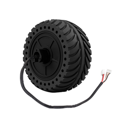
Based on the integrated development concept, DDSM115 is a high-reliability Permanent Magnet Synchronous Motor (PMSM) integrating an outer rotor brushless motor, encoder, and servo. With a compact structure, it is easy to install and can be operated stably. As it is small while with high torque, it can be applied for the following advanced robot projects such as robot joints, small AGV drive wheels, balance car drive wheels, and the development of vehicle platforms.
By optimizing the number of poles and slots, slot type, air gap, permanent magnet material, etc., it is ensured that the motor has greater torque output and smaller torque fluctuations, and realizes direct drive with low speed and high torque, providing users with high-performance direct-drive application solutions.
As the drive for the motor adopts the Field Oriented Control (FOC) algorithm and works with the built-in high-precision sensor, the motor can be precisely controlled with lower noise. The driver also has a complete and reliable OBD (Onboard diagnostics) monitoring mechanism and protection functions for the motor to ensure safe and reliable motor operation.
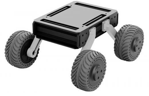
At the same time, we provide an open-source four-wheel drive off-road vehicle structure model for this type of direct-drive servo motor. You can download the model and project files here.
Note
- Please confirm whether the operating voltage is the voltage specified in this article (5S LiPo, 5s lithium battery (five lithium batteries in series) voltage range) before use.
- Please make sure the motor is used under the specified environment range (-20℃~45℃), the motor over-temperature protection threshold is 80°C, and the protection is released when the temperature is lower than 75°C.
- Please avoid immersing the motor in water, otherwise, it may cause abnormal operation or damage to the motor.
- Please ensure that the wiring is correct and stable before use to avoid poor contact.
- Please refer to the installation instructions before using the motor to ensure that the motor is installed correctly and firmly.
- Please refer to the installation instructions before using the motor to ensure that the external output part of the motor is installed correctly and firmly.
- Please avoid damage to the wire during use, otherwise, it may cause abnormal operation or damage to the motor.
- Do not touch the rotating part of the motor during use to avoid injury.
- When the motor outputs high torque, it will generate heat. Do not touch the motor to avoid burns.
- Do not disassemble the motor without permission, otherwise, it may cause abnormal operation or damage to the motor, and may bring safety hazards.
Feature
- Ultra-low noise
- High precision and zero-backlash
- Fast response, direct drive without delay
- Integrated motor and driver, compact structure and high integration
- Support RS485 communication mode
- Motor feedback information such as position, speed, current, error code, etc. can be obtained through communication.
- With Hall position detection, over-current protection, etc.
- Support electric brake
- No drive mechanical friction, drive efficiency close to 100%
Parameter
- No-load speed: 200±10rpm
- No-load current: ≦0.25A
- Rated speed: 115rpm
- Rated torque: 0.96Nm
- Rated current: 1.5A
- Maximum efficiency: ≥60%
- Locked-rotor torque: 2.0Nm
- Locked-rotor current: ≦2.7A
- Rated voltage: 18V DC (5S LiPo)
- Voltage range: 12-24V DC
- Torque constant: 0.75Nm/A
- Speed constant: 11.1rpm/V
- Operating temperature: -20~45℃
- Total weight: 765±15g
- Encoder resolution: 4096
- Relative accuracy: 1024
- Noise level: ≦50dB
- Degree of protection: IP54
- Single-wheel load: 10kg
Motor Interface and Cable Order
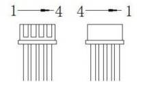
| Signal Cable (ZH1.5*4P) | Name | Type | Description |
|---|---|---|---|
| 1 | GND | Signal GND | Negative Electrode |
| 2 | A | DATA+ | 485 bus A |
| 3 | B | DATA- | 485 bus B |
| 4 | / | / | Reserved |
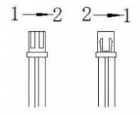
| Power cable (XH2.54*2P) | Name | Type | Description |
|---|---|---|---|
| 1 | VCC | Power input | Rated 18V DC |
| 2 | GND | Ground | Negative Electrode |
How To Use
- The simple control method is only used to verify the working principle of the motor and to do some simple tests. For the specific method, please refer to the chapter on the communication protocol.
- It is recommended to use USB to RS485 for the device with a USB interface to control the servo.
- You can refer to the signal line table #Motor Interface and Cable Order for the signal cable wiring and pin definition. Connect the DATA+ of the motor to the A+ of the converter, connect the DATA- of the motor to the B- of the converter, and the GND of the motor signal cable. Connect to the GND of the converter (it is recommended to connect GND, but if your RS485 interface does not have GND, you can leave it unconnected).
- For the wiring of the power cable, refer to the power cable table #Motor Interface and Cable Order above for the pin definition. The VCC of the power cable is connected to the positive pole of the 18V DC power supply (the voltage range of 5S LiPo is sufficient), and the GND of the power line is connected to the negative pole of the 18V DC power supply. Since the power of the motor is relatively large, the power supply needs to have enough power to drive the motor to work normally.
- Download OSDA open-source serial port assistant.
- Run the OSDA open source serial port debugging assistant, select the serial port of the device, select 115200 for the baud rate, check Hex to accept, check Hex to send, and then open the serial port to send commands to the motor.
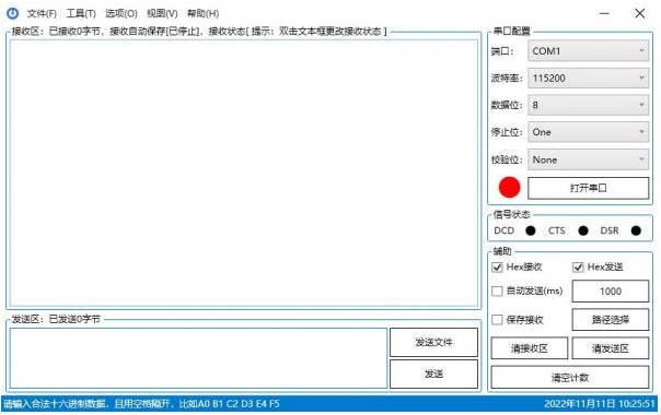
- Note that the motor will start to rotate after some commands are sent. Do not touch the rotating parts of the motor. If you do not have suitable structural parts to install the motor, be sure to prepare for power failure at any time, and do not give high-speed commands.
- The following is the 485 communication instruction set:
1. Switch to velocity loop (02), this command has no feedback.
01 A0 00 00 00 00 00 00 00 02
2. For additional feedback, query the motor mode
01 74 00 00 00 00 00 00 00 04
3. Brake command, valid in speed loop mode.
01 64 00 00 00 00 00 FF 00 D1
4. ID setting(01), send the command five times in a row
AA 55 53 01 00 00 00 00 00 00
5. ID query
C8 64 00 00 00 00 00 00 00 DE
6. Current loop command(-32767~32767 corresponds to -8A~8A)
01 64 F8 30 00 00 00 00 00 08 (-2000)
01 64 EC 78 00 00 00 00 00 D3 (-5000)
01 64 D8 F0 00 00 00 00 00 78 (-10000)
01 64 00 00 00 00 00 00 00 50 (0)
01 64 07 D0 00 00 00 00 00 27 (2000)
01 64 13 88 00 00 00 00 00 A7 (5000)
01 64 27 10 00 00 00 00 00 57 (10000)
7. Velocity loop commands(-330~330 rpm)
01 64 FF CE 00 00 00 00 00 DA (-50rpm)
01 64 FF 9C 00 00 00 00 00 9A (-100rpm)
01 64 00 00 00 00 00 00 00 50 (0rpm)
01 64 00 32 00 00 00 00 00 D3 (50rpm)
01 64 00 64 00 00 00 00 00 4F (100rpm)
8. Position loop commands(0~32767 corresponds to 0~360°)
01 64 00 00 00 00 00 00 00 50 (0)
01 64 27 10 00 00 00 00 00 57 (10000)
01 64 4E 20 00 00 00 00 00 5E (20000)
01 64 75 30 00 00 00 00 00 A7 (30000)
Communication Protocol
- Baudrate: 115200
- Data bits: 8bit
- Stop bit: 1bit
- Parity bit: none
- Data length: 10 bytes
- Reply form: one question and one answer
- Rate: up to 500Hz
- In current loop mode: -32767~32767 corresponds to the range -8~8A (non-motor current range), the data type is signed 16-bit
- In speed loop mode: -330~330, unit rpm, data type signed 16-bit
- In position loop mode: 0~32767 corresponds to 0°~360°, data type unsigned 16 bits
- Steps:
①Set the motor ID (save when power is off)
②Set the motor mode (current loop, speed loop, position loop, the default is speed loop)
③Send the given value
- CRC8 value:
- The value after the CRC8 check is performed on the values DATA[0]~DATA[8].
- CRC algorithm: CRC-8/MAXIM
- Polynomial: x8 + x5 + x4 +1
- The verification product stage can use this website to calculate the check digit: https://crccalc.com/
- Protocol 1: drive motor to rotate
Send to the motor:
| Data Field | DATA[0] | DATA[1] | DATA[2] | DATA[3] | DATA[4] | DATA[5] | DATA[6] | DATA[7] | DATA[8] | DATA[9] |
|---|---|---|---|---|---|---|---|---|---|---|
| Content | ID | 0x64 | Velocity/current/given position high 8 bits | Velocity/current/given position low 8 bits | 0 | 0 | Acceleration time | Brake | 0 | CRC8 |
Motor feedback:
| Data Field | DATA[0] | DATA[1] | DATA[2] | DATA[3] | DATA[4] | DATA[5] | DATA[6] | DATA[7] | DATA[8] | DATA[9] |
|---|---|---|---|---|---|---|---|---|---|---|
| Content | ID | Mode value | Torque current high 8 bits | Torque current low 8 bits | Velocity high 8 bits | Velocity low 8 bits | Position high 8 bits | Position low 8 bits | Error code | CRC8 |
- Acceleration time: valid in the speed loop mode, the acceleration time per 1rpm, the unit is 0.1ms. When it is set to 1, the acceleration time per 1rpm is 0.1ms. When it is set to 10, the acceleration time per 1rpm is 10*0.1 ms=1ms. When set to 0, the default is 1, and the acceleration time per 1rpm is 0.1ms.
- Brake: 0XFF other values do not brake, valid in speed loop mode.
- Protocol 2: get other feedback.
Send to the motor:
| Data Field | DATA[0] | DATA[1] | DATA[2] | DATA[3] | DATA[4] | DATA[5] | DATA[6] | DATA[7] | DATA[8] | DATA[9] |
|---|---|---|---|---|---|---|---|---|---|---|
| Content | ID | 0x74 | 0 | 0 | 0 | 0 | 0 | 0 | 0 | CRC8 |
Motor feedback:
| Data Field | DATA[0] | DATA[1] | DATA[2] | DATA[3] | DATA[4] | DATA[5] | DATA[6] | DATA[7] | DATA[8] | DATA[9] |
|---|---|---|---|---|---|---|---|---|---|---|
| Content | ID | Mode value | Torque current high 8 bits | Torque current low 8 bits | Velocity high 8 bits | Velocity low 8 bits | Winding temperature | U8 position value | Error code | CRC8 |
- U8 position value: 0~255 corresponds to 0~360°
- Winding temperature: ℃
- Error code:
| Error Code | BIT7 | BIT6 | BIT5 | BIT4 | BIT3 | BIT2 | BIT1 | BIT0 |
|---|---|---|---|---|---|---|---|---|
| Content | Save | Save | Save | Troubleshooting | Stall error | Phase overcurrent error | Overcurrent error | Sensor error |
For example, the error code 0x22, that is 0b00000010, means an overcurrent error.
- CRC8 value:
The value after performing CRC8 check on the value DATA[0]~DATA[8].
CRC algorithm: CRC-8/MAXIM
Polynomial: x8 + x5 + x4 + 1
- Motor mode switches sending protocol:
| Data Field | DATA[0] | DATA[1] | DATA[2] | DATA[3] | DATA[4] | DATA[5] | DATA[6] | DATA[7] | DATA[8] | DATA[9] |
|---|---|---|---|---|---|---|---|---|---|---|
| Content | ID | 0xA0 | 0 | 0 | 0 | 0 | 0 | 0 | 0 | Mode value |
Mode value:
0x01:set the current loop
0x02:set the velocity loop
0x03:set the position loop
The rotating velocity of the motor must be lower than 10rpm when switching to the position loop.
- Motor ID set the sending protocol:
| Data Field | DATA[0] | DATA[1] | DATA[2] | DATA[3] | DATA[4] | DATA[5] | DATA[6] | DATA[7] | DATA[8] | DATA[9] |
|---|---|---|---|---|---|---|---|---|---|---|
| Content | 0xAA | 0x55 | 0x53 | ID | 0 | 0 | 0 | 0 | 0 | 0 |
Note: When setting the ID, please ensure that there is only one motor on the bus. It is only allowed to be set once each time the power is turned on. The motor can be set after receiving 5 ID setting instructions.
- Motor ID query the sending protocol:
Send to the motor:
| Data Field | DATA[0] | DATA[1] | DATA[2] | DATA[3] | DATA[4] | DATA[5] | DATA[6] | DATA[7] | DATA[8] | DATA[9] |
|---|---|---|---|---|---|---|---|---|---|---|
| Content | 0xC8 | 0x64 | 0 | 0 | 0 | 0 | 0 | 0 | 0 | CRC8 |
Motor feedback:
| Data Field | DATA[0] | DATA[1] | DATA[2] | DATA[3] | DATA[4] | DATA[5] | DATA[6] | DATA[7] | DATA[8] | DATA[9] |
|---|---|---|---|---|---|---|---|---|---|---|
| Content | ID | Mode value | Torque current high 8 bits | Torque current low 8 bits | Velocity high 8 bits | Velocity low 8 bits | Position high 8 bits | Position low 8 bits | Error code | CRC8 |
Note: Please ensure that there is only one motor on the bus when querying the ID.
Protection Rules
1. Bus overcurrent protection threshold: 3A, trigger shutdown protection after overcurrent occurs, and release after 5S.
2. Motor over-temperature protection threshold: 80°C, the protection will be released when the temperature is lower than the threshold by 5°C.
3. Phase current protection threshold: 4.6A, trigger shutdown protection after overcurrent occurs, and release after 5S.
4. Locked rotor protection: the blocked rotor lasts for more than 5S to trigger the protection, and it will be released after 5S.
Installation Guide
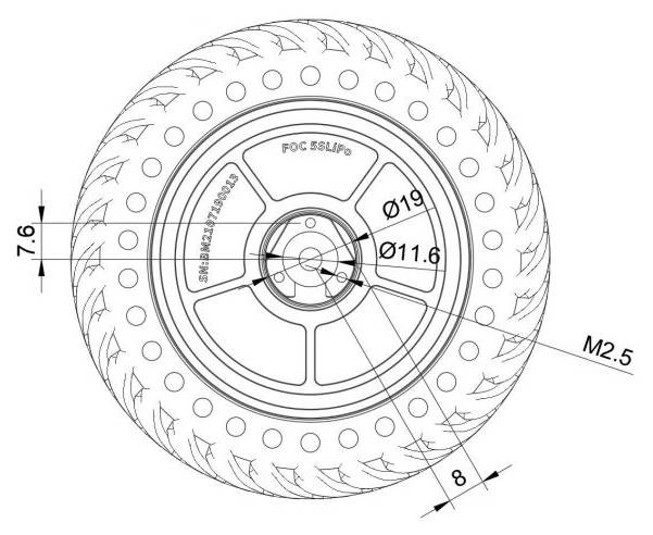
- The direct drive servo hub motor is installed with rubber tires when leaving the factory. The pattern of the rubber tires has directions. You can remove the three M2.5*8 inner hexagon screws on the front black cover. After removing the black cover, After that, you can take down the rubber tire, and then change the angle to install the tire.
- The mounting threaded hole of the motor mounting section is M2.5, 6mm deep, and positioned as an outer circle with a diameter of 15.2mm and a flat position with a diameter of 8mm. Please select the appropriate screws for installation.
Resource
3D Model
2D Drawing
Open Source Structure
