- sales/support
Google Chat:---
- sales
+86-0755-88291180
- sales01
sales@spotpear.com
- sales02
dragon_manager@163.com
- support
tech-support@spotpear.com
- CEO-Complaints
zhoujie@spotpear.com
- Only Tech-Support
WhatsApp:13246739196
- Purchase/Shipping/Refund
WhatsApp:13424403025
- HOME
- >
- ARTICLES
- >
- LuckFox
- >
- LuckFox Pico
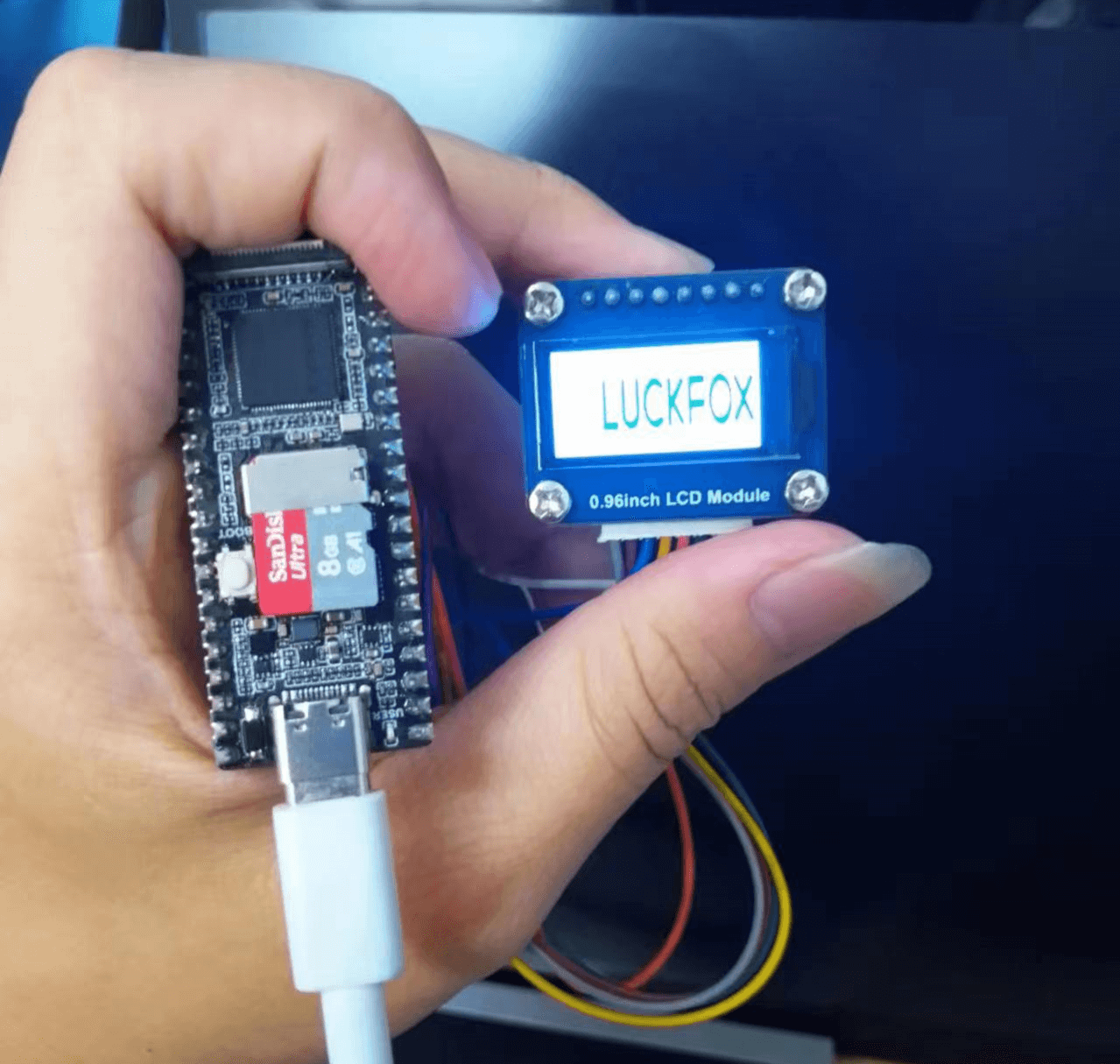
Luckfox Pico RV1103/RV1106【SPI driven LCD】
Download the SPI driver LCD example code
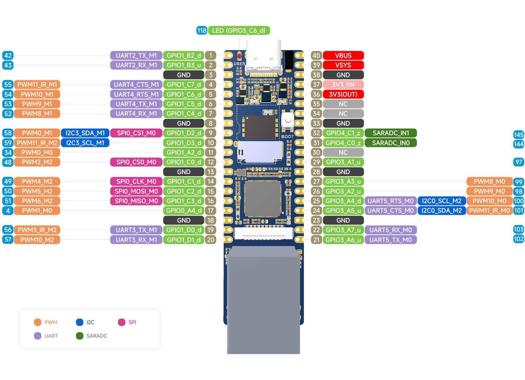
1】Pin connection diagram:
Pico pinout diagram
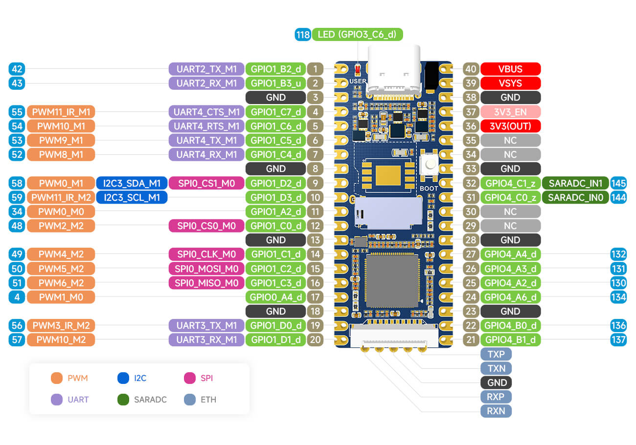
pico-plus pinout diagram
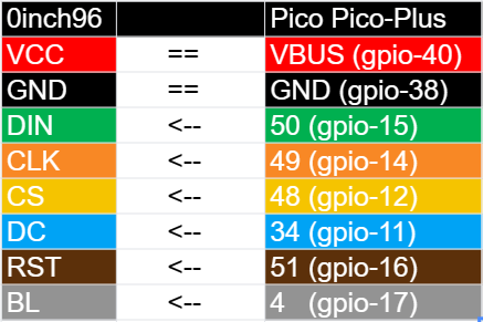
lcd module pinout diagram for Pico Pico-Plus
2】Use a self-compiled image (optional):
Modify the device tree file:
(You can use pre-compiled images without the need to modify the device tree yourself; image)
You need to add the pin definitions related to the LCD in the device tree and enable the SPI functionality.
Path to the device tree file:
Luckfox Pico:<SDK Path>/sysdrv/source/kernel/arch/arm/boot/dts/rv1103g-luckfox-pico.dts
Luckfox Pico Plus:<SDK Path>/sysdrv/source/kernel/arch/arm/boot/dts/rv1103g-luckfox-pico-plus.dts
Define GPIO:
To define a GPIO, usually two code segments need to be added. Note that the button is active at low level and requires pull-up. Here is an example showing how to add the definition of GPIO1_C7_d pin in the device tree.
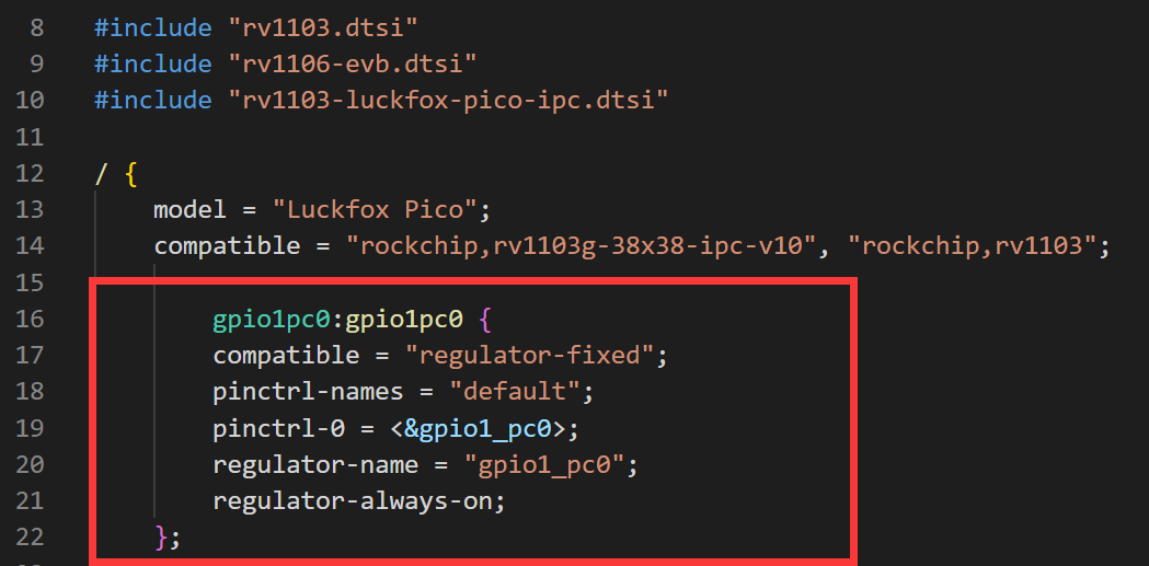
gpio1pc0:gpio1pc0 {
compatible = "regulator-fixed";
pinctrl-names = "default";
pinctrl-0 = <&gpio1_pc0>;
regulator-name = "gpio1_pc0";
regulator-always-on;
};
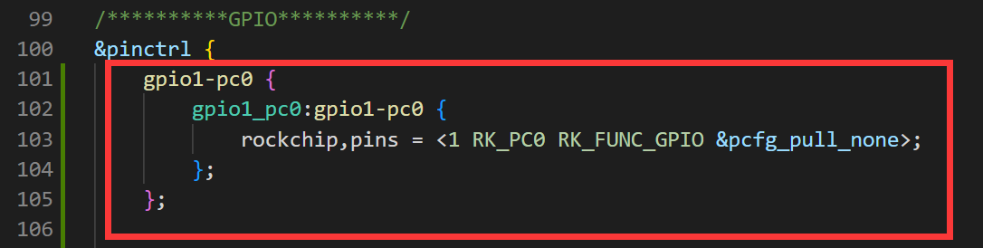
&pinctrl {
gpio1-pc0 {
gpio1_pc0:gpio1-pc0 {
rockchip,pins = <1 RK_PC0 RK_FUNC_GPIO &pcfg_pull_none>;
};
};
};
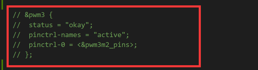
Commenting out the peripheral function of a pin:
To comment out the peripheral function of a pin, you can achieve it by commenting out the corresponding peripheral node in the device tree. Here is an example showing how to disable the PWM function of the GPIO1_C7_d pin in the device tree.
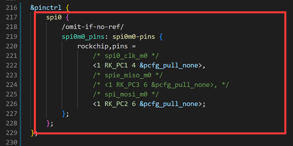
Configuring SPI:
When configuring SPI, GPIO1_C2_d is used as the reset pin for the LCD. We need to configure it as a regular IO, so it is not configured as the MISO pin for SPI here, as shown in the diagram below (please refer to the comment on line 208). To make SPI work properly, you also need to configure the SPI controller and define the required SPI pins in the device tree. Here is an example showing how to configure SPI in the device tree.
&pinctrl {
spi0 {
/omit-if-no-ref/
spi0m0_pins: spi0m0-pins {
rockchip,pins =
/* spi0_clk_m0 */
<1 RK_PC1 4 &pcfg_pull_none>,
/* spie_miso_m0 */
<1 RK_PC3 6 &pcfg_pull_none>,
/* spi_mosi_m0 */
<1 RK_PC2 6 &pcfg_pull_none>;
};
};
};
Compile and select branch ./build.sh lunch
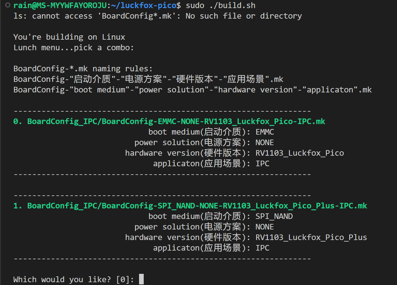 Choose 0 to compile the pico-related image.
Choose 1 to compile the pico-plus-related image.
To compile with one click or only compile the kernel:
To compile with one click, use "./build.sh".
To compile only the kernel, use "./build.sh kernel".
3】Use a pre-configured image (optional):
Download the SPI driver LCD example code
4】 Write the image to Pico:
Burn the image using an SD card
5】Download the example package and transfer the "c" folder to the Pico development board:
Please use the ADB tool to transfer the entire "c" folder to the Pico development board.
adb push Pico_LCD_Module_Code\Luckfox_Pico\c /
6】Grant permissions and run the main program:
Grant executable permissions chmod -R x ./c
Run the main program based on the LCD size ./main 0.96
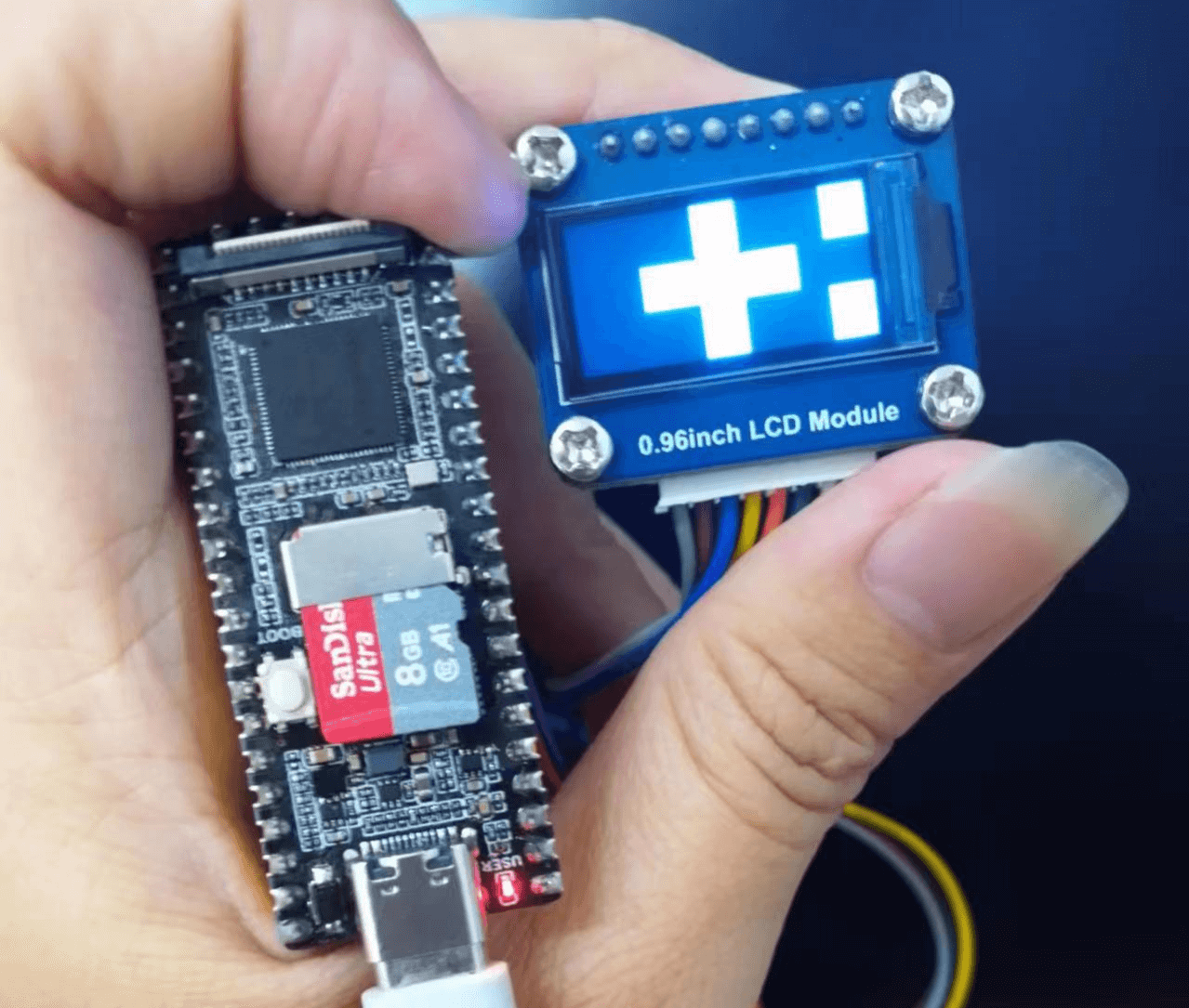
7】Achieve the desired effect: