


- sales/support
Google Chat:---
- sales
+86-0755-88291180
- sales01
sales@spotpear.com
- sales02
dragon_manager@163.com
- support
tech-support@spotpear.com
- CEO-Complaints
zhoujie@spotpear.com
- Only Tech-Support
WhatsApp:13246739196
- Purchase/Shipping/Refund
WhatsApp:13424403025
CM4S08032-Package-A User Guide
Overview
This is an IO board for evaluating the Raspberry Pi CM4 or being integrated into end products. the board feature PoE function, it can be used for all variants of CM4.
Precautions
1. DO NOT hot-plug any devices except the USB and HDMI.
2. Please check the fan voltage before connection, support 5V and 12V. The default connection is 5V and you can modify the FAN_VCC jump cap to switch.
3. Micro USB is used as a USB SLAVE interface to write images, not as an OTG interface.
4. Provide 5V 1.5A for CM4 to ensure that it is in normal use. Otherwise, there may be problems such as automatic shutdown, frequency reduction, and so on.
5. Onboard 4-ch USB 3.2 Gen1 connector by default.
6. When using the POE function, check whether the switch supports PoE for the 802.3af network standard.
7. When POE is required, connect the POE jumper cap to the EN position.
8: Two DISP interfaces cannot be used together by default.
Dimension
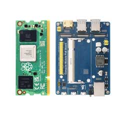
Compute_Module 4 POE Board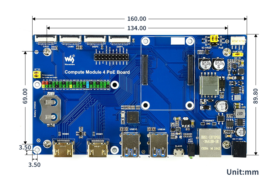
Compute_Module 4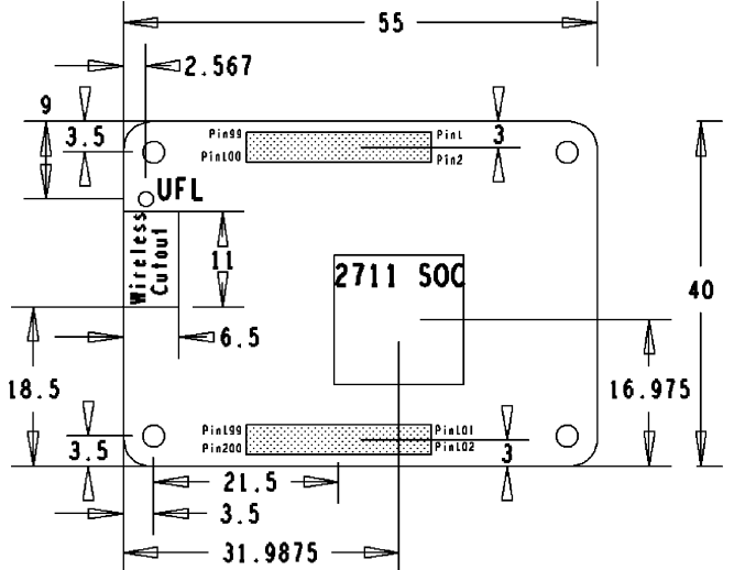
What's on board
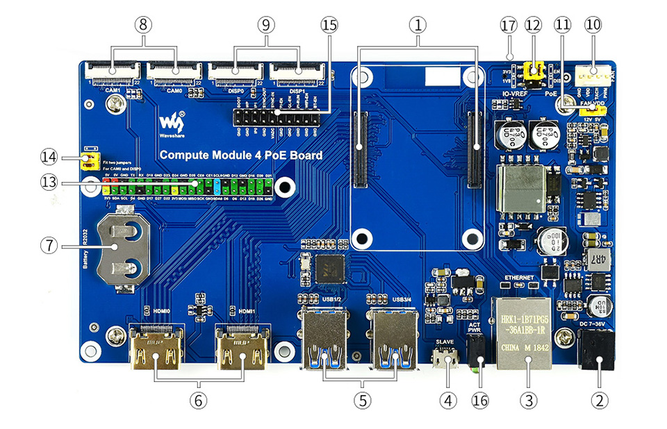
| No. | Component | Description | |
| 1 | CM4 connector | Suitable for all variants of Compute Module 4 | |
| 2 | DC power port | 7~36V DC wide voltage supply, 24W or higher power supply is recommended. | |
| 3 | Gigabit Ethernet RJ45 with PoE support | 10/100M auto-negotiation, for connecting router or switch with PoE function | |
| 4 | USB SLAVE Interface | Writing emmc for Compute Module 4 | |
| 5 | USB3.2 Interface | 4 x USB 3.2 Gen1 interface for USB devices. | |
| 6 | HDMI Interface | Dual HDMI ports for dual 4K 30fps output. | |
| 7 | RTC | RTC battery holder, for installing CR2032 batteries, allows RTC-related functions like wakeup, shutdown, reboot, and more | |
| 8 | CAM | 2x MIPI CSI camera connectors. | |
| 9 | DISP | 2x MIPI DSI display connectors. | |
| 10 | FAN | Fan header, support PWM Fan. | |
| 11 | FAN Power Select | 5V or 12V voltage to drive the fan | |
| 12 | IO-VREF/PoE selection | IO-VREF: CM4 IO logic level: 3.3V or 1.8V PoE: enable (EN) or disable (DIS) | |
| 13 | 40PIN GPIO header | For connecting Raspberry Pi HATs | |
| 14 | CAM0 and DISP0 I2C bus | fit the jumpers when using CAM0 or DISP0 | |
| 15 | Misc configurations | Special function pins | |
| 16 | Dual LED indicators | red: Raspberry Pi power indicator green: Raspberry Pi operating status indicator | |
| 17 | TF card slot (bottom side) | Insert a Micro SD card with a pre-burnt system, to start up Compute Module 4 Lite |
Special Function Pin Description
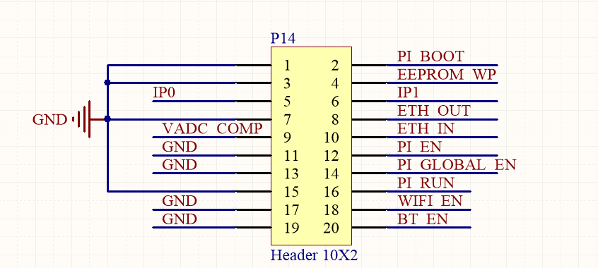
| Name | Description | |
| 1 | PI BOOT | Low level, Pi booted from USB SLAVE port |
| 2 | EEPROM WP | Low level, prevents EEPROM from being overwritten |
| 3 | IP1/0 | CM4 board MXL7704 AN1/0 pin |
| 4 | VADC COMP | Composite video output |
| 5 | ETH IN | ETH simultaneous signal |
| 6 | PI_EN | Synchronized with PI_RUN signal |
| 7 | PI_GLOBAL_EN | CM4 onboard MXL7704 power enable pin, disabled for low level |
| 8 | PI_RUN | CM4 status indication, high means power on, force pull low to force restart CM4 |
| 9 | WIFI_EN | WIFI enable, low level disable, enabled when not connected |
| 11 | BT_EN | Bluetooth enable, low disable, enabled when not connected |
Note
Do not plug or unplug any device while the base board is powered on.
Writing Image
- Write Image for Compute Module Boards eMMC version
- Write Image for Compute Module Boards Lite version
RTC FAN
- Note: Please connect the fan before turning on the power of the baseboard and then complete the test. Please do not connect the fan after the baseboard is powered on, because the fan control chip has been powered on, otherwise, the chip will be burned!
- Note: Before connecting, please confirm whether the rated voltage of the fan is consistent with the voltage connected to the fan.
Please note that DSI and CSI are prohibited when using RTC.
I2C-10 is used by default.
RTC (PCF85063a) on i2c-10, address is 0 x 51 (7-bit address)
FAN (EMC2301) on i2c-10, address is 0 x 2f (7-bit address)
If you need to add it to your program instead of the kernel, you can refer to the C and Python demo reference click here
RTC
sudo nano /boot/config.txt
 #Add the following lines at the end
 dtparam=i2c_vc=on
 dtoverlay=i2c-rtc,pcf85063a,i2c_csi_dsi
 #Add # in front of dtparam=audio=on
 #dtparam=audio=on
 #Save and exit, restart
 sudo reboot
How to use Hwclock
Synchronize system clock to hardware clock:
sudo hwclock -w
Synchronize hardware clock to system clock:
sudo hwclock -s
 #The network or the NTP needs to be closed, otherwise it will be changed back.
Set the hardware clock time:
sudo hwclock --set --date="9/8/2021 16:45:05"View hardware clock:
sudo hwclock -r
Display version information:
sudo hwclock --verbose
Fan
1: Check if the kernel version is higher than or equal to 6.1.31.
uname --all
2: Add the following content at config.txt:
dtoverlay=i2c-fan,emc2301,i2c_csi_dsi,midtemp=45000,maxtemp=650003: For more parameters, you can refer to this link
Troubleshooting
1: After configuration, you can use the command "i2cdetect -y 10" to check whether the configuration is valid, and the valid I2C address should be UU without digits.
2: RTC value is not accurate, or an invalid prompt appears, check whether the RTC battery is connected and whether the voltage of the RTC battery is normal.
3: All configurations need to be rebooted after being added to take effect.
4: If the fan does not rotate after adding the fan driver, you can press "1" to troubleshoot and check whether the configuration is effective. If it is valid, then you can check whether the kernel version is higher or equal to 6.1.31 (uname --all). If the version is lower than 6.1.31, this kernel cannot work. For more details, you can refer to this link.
CSI DSI
Configuration file
CSI and DSI are disabled by default. When using the camera and DSI, it will occupy three I2C devices: I2C-10, I2C-11, and I2C-0.
- Open a terminal and run the following commands:
sudo apt-get install p7zip-full -y
wget https://files.waveshare.com/upload/7/75/CM4_dt_blob.7z
7z x CM4_dt_blob.7z -O./CM4_dt_blob
sudo chmod 777 -R CM4_dt_blob
cd CM4_dt_blob/
# If using two cameras and DSI1, please execute:
sudo dtc -I dts -O dtb -o /boot/dt-blob.bin dt-blob-disp1-double_cam.dts
# When using any DSI, there is no image output on HDMI1. Even if you do not connect a DSI screen, as long as the corresponding file is compiled, there will be no output on HDMI1.
# To restore it, simply delete the corresponding dt-blob.bin file: sudo rm -rf /boot/dt-blob.bin
#Execution is complete, power off and reboot CM4
New Version (Bullseye)
Camera Config
- Execute the following commands to edit "/boot/config.txt" file.
sudo nano /boot/config.txt
- Block or remove the automatic camera detection statement:
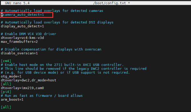
- Add the driver of the camera you are using, here I take IMX219 as an example and connect it to CAM0, and attach the adapter.
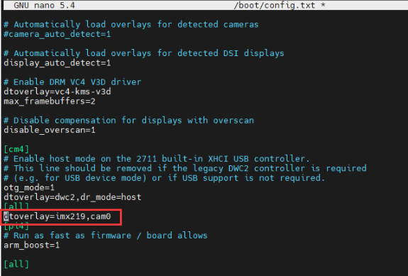
Model CAM0 Set Sentence CAM1 Set Sentence OV9281 dtoverlay=ov9281,cam0 dtoverlay=ov9281,cam1 IMX290/IMX327 dtoverlay=imx290,clock-frequency=37125000,cam0 dtoverlay=imx290,clock-frequency=37125000,cam1 IMX378 dtoverlay=imx378,cam0 dtoverlay=imx378,cam1 IMX219 dtoverlay=imx219,cam0 dtoverlay=imx219,cam1 IMX477 dtoverlay=imx477,cam0 dtoverlay=imx477,cam1 IMX708 dtoverlay=imx708,cam0 dtoverlay=imx708,cam1 - If you are using the official Raspberry Pi camera and only one camera is connected, there is no need to set the config file. If it is not an official camera, set the "dtoverlay" statement without the "cam" suffix.
- CM4-NANO - only CAM0 is used, so you only need to add "dtoverlay=imx219,cam0".

5. Ctrl+x to exit the editor.
6. Reboot the Raspberry Pi.
sudo reboot
Camera Test
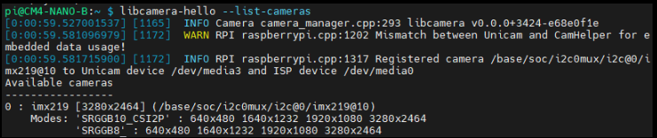
- Enter the camera detection command, you can see that the camera is detected by now.
libcamera-hello --list-cameras
- Display the camera screen on the desktop.
- Taking photos.
libcamera-jpeg -o test.jpg
- Record a video of 10s.
libcamera-vid -t 10000 -o test.h264
Other Commands:
libcamera-hello -t
Check whether the camera is detected:
libcamera-hello --list-cameras
Open the corresponding cameras:
libcamera-hello  --camera 1
libcamera-hello  --camera 0
Take a photo:
libcamera-jpeg -o test.jpg
#Add --camera to specify a camera
Old Version (Buster)
Camera Config
- 1. Execute the following command to enter the Raspberry Pi configuration.
- Test the recording function:
- Where -t 10000 means recording for 10 seconds, users can adjust according to their own needs.
- Please refer to CSI.
sudo raspi-config
2. Choose Interfacing Options and enter.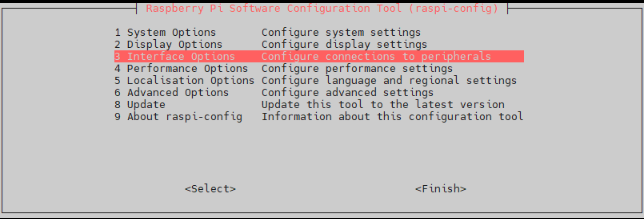
3. Choose Camera: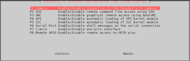
4. Choose to enable the camera interface.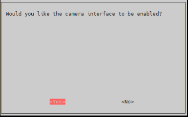
5. The system prompts as follows: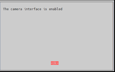
6. Back to the main interface, select Finish.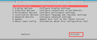
7. Reboot the system.
Camera Test
raspistill -o image.jpg
raspivid -o video.h264 -t 10000
Resource
Document
- Schematic
- CSI Camera Reference
- DSI Display Reference
- Raspberry Pi Compute Module 4 IO Board Brief
- Raspberry Pi Compute Module 4 IO Board Datasheet
3D Drawing
Demo codes
Software
FAQ
Question:What if I cannot search for the I2C address of the RTC/FAN controller using i2cdetect -y 10?
a) Check if dtparam -audio -on is blocked in /boot/config.txt.
b) Check if the /boot/dt-blob.bin file exists, if it does, please delete it.
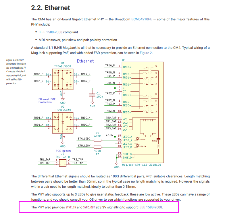
Question:At the location of the special function pins (close to the top of the board at the disp0 and disp1 connectors) two pins are called "SYNC_OUT" and "SYNC_IN". Which pin is used to receive incoming pulses from extern modules (these extern modules would send pulses to the Raspberry Pi CM4)?
Support
Monday-Friday (9:30-6:30) Saturday (9:30-5:30)
Email: services01@spotpear.com
[Tutorial Navigation]
- Overview
- Resource
- FAQ
- Question:What if I cannot search for the I2C address of the RTC/FAN controller using i2cdetect -y 10?
- Question:At the location of the special function pins (close to the top of the board at the disp0 and disp1 connectors) two pins are called "SYNC_OUT" and "SYNC_IN". Which pin is used to receive incoming pulses from extern modules (these extern modules would send pulses to the Raspberry Pi CM4)?
- Support