


- sales/support
Google Chat:---
- sales
+86-0755-88291180
- sales01
sales@spotpear.com
- sales02
dragon_manager@163.com
- support
tech-support@spotpear.com
- CEO-Complaints
zhoujie@spotpear.com
- Only Tech-Support
WhatsApp:13246739196
- Purchase/Shipping/Refund
WhatsApp:13424403025
Raspberry Pi 2-Channel Isolated CAN Bus Expansion User Guide
Overview
Introduction
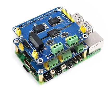
2-CH CAN HAT+ is an isolated expansion board for Raspberry Pi, supports dual-channel CAN communication, and features multi-protection circuits, wide voltage input, and so on.
Features
- Designed for Raspberry Pi, support Raspberry Pi Zero/Zero W/Zero WH/2B/3B/3B+/4B/5.
- Standard HAT+ design, with onboard EEPROM chip.
- Adopts MCP2515 and SN65HVD230 dual-chip solution, allowing 2-channel CAN communication.
- Integrated power isolation, providing stable isolated voltage, requires no extra power supply for the isolated terminal.
- Onboard digital isolation chip, signal isolation communication is safer, more stable, and better anti-interference.
- Onboard SM24CANB (transient voltage suppressor), provides ESD protection and transient peak voltage protection.
- Onboard voltage conversion circuit, select 3.3V/5V operating voltage by jumper.
- Onboard 120Ω terminal resistor, enable through the jumper cap.
- Elicits the SPI control interface, for connecting with host control boards like STM32/Arduino.
- Provides online supporting information manuals and demos.
Parameters
- Input voltage: 5V, 7~36V
- Logic level: 3.3V/5V
- CAN controller: MCP2515
- CAN receiver: SN65HVD230
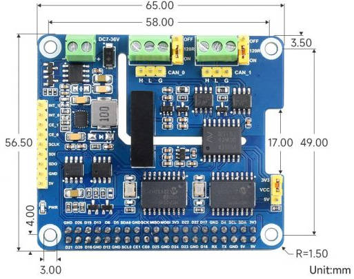
- Dimensions: 65.0x56.5mm
- Mounting hole diameter: 3.0mm
Interface Description
CAN Interface Bus
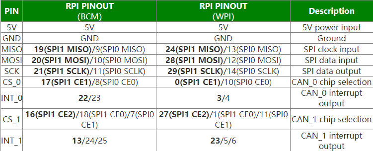
Note: The bolded are the default connection pins.
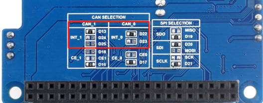
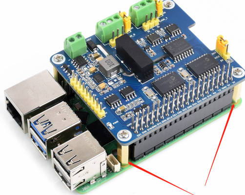
NOTE
INT_0 is soldered by PIN22 by default, and INT_1 is soldered by PIN13 by default.

If you need to modify the pins, you need to modify the soldering pad of the PCBA board, and modify the corresponding setting of /boot/config.txt (Pi5 is /boot/firmware/config.txt).

For example. if you need to change INT_1 from the default PIN13 to PIN24, you need to solder the 0 ohm at the arrow of PIN13 to PIN24.
CAN bus
CAN module could process packets transmitted/received on the CAN bus. When the packet is sent, the packet is first loaded into the correct packet buffer and control register. Use the SPI interface to set the corresponding bits on the control register or enable the transmit pin for transmitting. Registers could be read to detect communication states and errors. It will first check if there are any errors of packets detected on the CAN bus, then match it with a filter that is defined by the user to determine whether to move the message to one of the two receive buffers.
Since the Raspberry Pi itself does not support the CAN bus, you can use a CAN controller with an SPI interface along with a transceiver for CAN functionality.
Microchip’s MCP2515 is a stand-alone Controller Area Network (CAN) protocol controller that implements the CAN specification, version 2.0B. It is capable of transmitting and receiving both standard and extended data and remote frames. The MCP2515 has two acceptance mask registers and six acceptance filter registers to filter out unwanted packets, thereby reducing the host MCUs overhead. The MCP2515 interfaces with microcontrollers (MCUs) via an industrial standard Serial Peripheral Interface (SPI). Also, the Raspberry Pi connects to the chip through the SPI interface, for the Raspberry Pi to use the chip does not need to write a driver, only needs to open the kernel driver in the device tree.
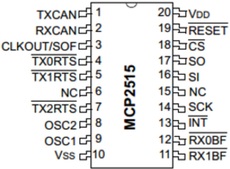
Refer to the datasheet for more details.
Dimensions
Raspberry Pi Guide
The working voltage level of Raspberry Pi is 3.3V, therefore we need to jump the logical voltage pin of the 2-CH CAN HAT+ to 3.3V as below:
Note: When connecting to the Raspberry Pi 2b/3b/4b/5 boards, please fix it with copper standoffs to avoid the back of the CAN terminal touching the HDMI interface causing a short circuit, and avoid wrong connection or poor contact:
Install libraries
- Install BCM2835, open the Raspberry Pi terminal, and run the following commands:
wget http://www.airspayce.com/mikem/bcm2835/bcm2835-1.60.tar.gz
tar zxvf bcm2835-1.60.tar.gz
cd bcm2835-1.60/
sudo ./configure
sudo make
sudo make check
sudo make install
# For More: http://www.airspayce.com/mikem/bcm2835/
- Install wiringPi
wiringPi
32-bit Raspberry Pi System
#Open the Raspberry Pi terminal and run the following command
cd
sudo apt-get install wiringpi
#For Raspberry Pi systems after May 2019 (earlier than that can be executed without), an upgrade may be required:
wget https://project-downloads.drogon.net/wiringpi-latest.deb
sudo dpkg -i wiringpi-latest.deb
gpio -v
# Run gpio -v and version 2.52 will appear, if it doesn't it means there was an installation error

# Bullseye branch system using the following command:
git clone https://github.com/WiringPi/WiringPi
cd WiringPi
./build
sudo gpio -v
# Run gpio -v and version 2.70 will appear, if it doesn't it means there was an installation error
64-bit Raspberry Pi System
Copy the resource package to the Raspberry Pi using the command:
wget https://files.waveshare.com/upload/8/8c/WiringPi-master.zip
(optional, you can skip this step if you have used the unzip command) Install the unzip environment:
sudo apt-get install unzip
Go to the file location and execute the unzip command:
unzip WiringPi-master.zip
Go to the file directory (go to the "WiringPi-master" folder):
cd WiringPi-master/
Execute sudo ./build
sudo ./build
(optional, see point 4 for errors) If ./build does not work, execute "chmod +x ./build" and then execute"sudo ./build":
chmod +x ./build
E
- Install Python Function library:
#python2
sudo apt-get update
sudo apt-get install python-pip
sudo apt-get install python-pil
sudo apt-get install python-numpy
sudo pip install RPi.GPIO
sudo pip install spidev
sudo pip install python-can
#python3
sudo apt-get update
sudo apt-get install python3-pip
sudo apt-get install python3-pil
sudo apt-get install python3-numpy
sudo pip3 install RPi.GPIO
sudo pip3 install spidev
sudo pip3 install python-can
- Find the corresponding product on the official website, open the download path in the product information, and download the sample demo in the wiki:
- Get the unzipped package, unzip it, and copy the demo to the Raspberry Pi.
Preparation
Enable SPI Interface
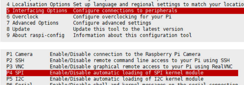
- Open the Raspberry Pi terminal, and input the following commands to enter the configure interface:
sudo raspi-config
Select Interfacing Options -> SPI -> Yes to enable SPI interface
And then reboot the Raspberry Pi:
sudo reboot
Make sure that the SPI is not occupied by other devices, you can check in /boot/config.txt.
Modify Script config.txt
Insert the module into Raspberry Pi, and then modify the boot script config.txt:
sudo nano /boot/config.txt #pi5 is /boot/firmwave/config.txt
Add these statements at the last line:
dtparam=spi=on
dtoverlay=i2c0
dtoverlay=spi1-3cs
dtoverlay=mcp2515,spi1-1,oscillator=16000000,interrupt=22
dtoverlay=mcp2515,spi1-2,oscillator=16000000,interrupt=13
- Reboot the Raspberry PI to apply all Settings:
sudo reboot
- After rebooting the Raspberry Pi, and view SPI information:
dmesg | grep spi1
- Enable CAN:
sudo ip link set can0 up type can bitrate 1000000
sudo ip link set can1 up type can bitrate 1000000
sudo ifconfig can0 txqueuelen 65536
sudo ifconfig can1 txqueuelen 65536
- For more commands about CAN kernel:
https://www.kernel.org/doc/Documentation/networking/can.txt
- Run ifconfig:
ifconfig
- Turn off CAN:
sudo ifconfig can0 down
sudo ifconfig can1 down
Test
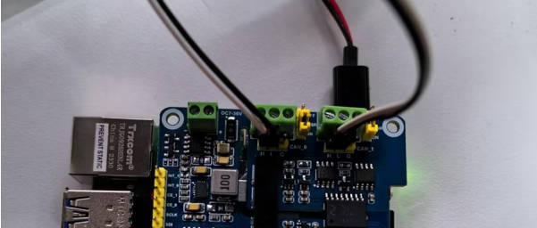
If you only have one 2-CH CAN HAT+, you can connect CAN0_H to CAN1_H, and CAN0_L to CAN1_L of the module as shown in the following figure:
- Install can-utils:
sudo apt-get install can-utils
- Open two terminal windows:
One inputs commands to receive CAN0 data:
candump can0
Another one inputs commands to send CAN1 data:
cansend can1 000#11.22.33.44
- The demonstration effect is as follows: (receiving on the left, sending on the right.)
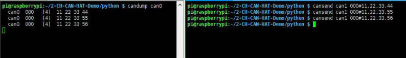
If you have two 2-CH CAN HAT+s, you can directly connect CAN_H and CAN_L between them. The effect is the same as the above, pay attention to match the communication rate, identify the ID, and output the interface serial number.
Python Example
- Browse the catalog:
- Run receive.py on the receiving terminal:
sudo python reveive.py
- Run send.py on the sending terminal:
sudo python send.py
It should be noted that the sender here is using CAN1 to send, the receiver is CAN0, the specific modifications can refer to the following code analysis.
Demo Analysis
【Python Demo】
The demo codes provided are based on Python, please check that you installed the python-can library.
Before you send data, you should create a CAN device first as only the MCP2515 kernel is booted earlier:
os.system('sudo ip link set can0 type can bitrate 100000')
os.system('sudo ifconfig can0 up')
The above code initializes the CAN0 configuration, and specify the CAN0 as the receiver/sender. If you want to change it to CAN1, you can use this one:
os.system('sudo ip link set can1 type can bitrate 100000')
os.system('sudo ifconfig can1 up')
Step 1: Connect to CAN Bus
can0 = can.interface.Bus(channel = 'can0', bustyp = 'socketcan_ctypes')
- Change to CAN1 as shown below:
can0 = can.interface.Bus(channel = 'can1', bustyp = 'socketcan')
Step 2: Create Message
msg = can.Message(arbitration_id=0x123, data=[0, 1, 2, 3, 4, 5, 6, 7], extended_id=False)
Step 3: Send Message
can0.send(msg)
- Change to CAN1 as shown below:
can1.send(msg)
- Finally, close the CAN device:
os.system('sudo ifconfig can0 down')
- Change to CAN1 as shown below:
os.system('sudo ifconfig can1 down')
- Receive data:
msg = can0.recv(10.0)
The variable of "recv()" function is the timeout of receiving.
For more information, please refer to: https://python-can.readthedocs.io/en/stable/interfaces/socketcan.html
【WringPi Demo】
- Blocking the reception, the Raspberry Pi opens the terminal and runs:
cd 2-CH_CAN_HAT_Code/wiringPi/receive/
make clean
sudo make
sudo ./can_receive
- Sending, the Raspberry Pi opens the terminal and runs:
cd 2-CH_CAN_HAT_Code/ wiringPi/receive/
make clean
sudo make
sudo ./can_send
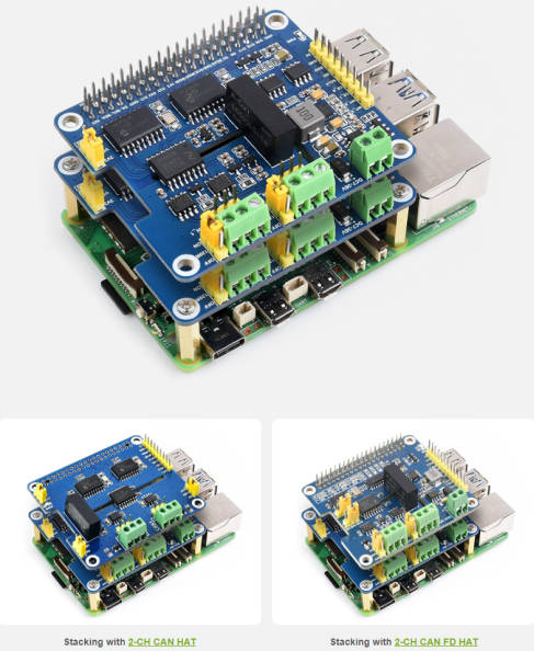
Stackable Usage
- 2-CH CAN HAT+ cannot be stacked directly with itself, it needs to be adjusted to the backside SPI chip selection before it can be stacked.
- Stack with 2-CH CAN HAT: only need to modify config.txt.
dtparam=spi=on
dtoverlay=i2c0
dtoverlay=spi1-3cs
dtoverlay=mcp2515,spi1-1,oscillator=16000000,interrupt=22
dtoverlay=mcp2515,spi1-2,oscillator=16000000,interrupt=13

dtoverlay=mcp2515,spi0-0,oscillator=16000000,interrupt=23
dtoverlay=mcp2515,spi0-1,oscillator=16000000,interrupt=25
- Stack with 2-CH CAN FD HAT: only need to modify config.txt.
dtparam=spi=on
dtoverlay=i2c0
dtoverlay=spi1-3cs
dtoverlay=mcp2515,spi1-1,oscillator=16000000,interrupt=22
dtoverlay=mcp2515,spi1-2,oscillator=16000000,interrupt=13

dtoverlay=mcp251xfd,spi0-0,interrupt=25
dtoverlay=mcp251xfd,spi1-0,interrupt=24
Resource
Document
Demo
Related Resource
FAQ
Question:Does the 2-CH CAN HAT+ support stacking multiple 2-CH CAN HATs, or stacking other HAT expansion boards?
Stacking multiple 2-CH CAN HAT+ expansion boards is supported, interfaces and drivers can be selected via the back resistor; if other HAT are stacked, if the interfaces and drivers do not conflict, theoretically it's stackable,for example, 2-CH CAN HAT, 2-CH CAN FD HAT, and 2-CH RS485 HAT are stackable with 2-CH CAN HAT+.
Question:Can multiple devices be connected to one CAN interface?
Yes. CAN bus can be connected to multiple CAN slaves in parallel, but the addresses should not conflict, and the actual data communication volume and interference should be considered, subject to the actual measurement.
Question:In addition to CAN_H, CAN_L, and GND of the CAN interface of the module, what is the purpose of the GND?
Ground pin, common ground can ensure the stability and reliability of the signal, to avoid signal interference and noise. The CAN itself is a differential signal line, if the customer's CAN device does not have a GND pin, it can also be left unconnected.
Question:Why does CAN driver install configuration fail?
You can try to update the kernel version, the commands are as follows::
sudo apt update
sudo apt upgrade
uname --all
Question:Why does CAN initialization fail?
If the initialization fails, you can restart the Raspberry Pi or other main control platform development boards to ensure that the connection is correct, refer to the wiki to carefully check whether there is any leakage in the configuration and whether the logic voltage jumper pin is selected correctly.
Question:Is pin G of the CAN interface connected?
G is the signal ground, also called isolated ground. In the industrial environment, CAN is subject to changeable surroundings and to ensure stability, the G of the two communication modules need to be connected.
Question:The CAN communication speed cannot reach the maximum value?
The chip is affected by many factors such as the surrounding environment, communication distance, wires, software, and so on. During high-speed communication, the data baud rate may not reach the nominal maximum rate. Users need to ensure stability and select a suitable communication speed according to actual measurements.
Support
Monday-Friday (9:30-6:30) Saturday (9:30-5:30) -China time
Email: services01@spotpear.com
Raspberry Pi 2-Channel Isolated CAN Bus Expansion HAT Dual Chips Solution Built-In Multi Protections
[Tutorial Navigation]
- Overview
- Raspberry Pi Guide
- Resource
- FAQ
- Question:Does the 2-CH CAN HAT+ support stacking multiple 2-CH CAN HATs, or stacking other HAT expansion boards?
- Question:Can multiple devices be connected to one CAN interface?
- Question:In addition to CAN_H, CAN_L, and GND of the CAN interface of the module, what is the purpose of the GND?
- Question:Why does CAN driver install configuration fail?
- Question:Why does CAN initialization fail?
- Question:Is pin G of the CAN interface connected?
- Question:The CAN communication speed cannot reach the maximum value?
- Support