


- sales/support
Google Chat:---
- sales
+86-0755-88291180
- sales01
sales@spotpear.com
- sales02
dragon_manager@163.com
- support
tech-support@spotpear.com
- CEO-Complaints
zhoujie@spotpear.com
- Only Tech-Support
WhatsApp:13246739196
- Purchase/Shipping/Refund
WhatsApp:13424403025
- HOME
- >
- ARTICLES
- >
- LuckFox
- >
- Luckfox PICO
RGB Screen User Guide
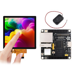
RGB screen
The LuckFox Pico Ultra and LuckFox Pico Ultra W now support RGB screens with a parallel RGB LCD interface. The image data is transmitted in RGB666 format, utilizing 6 bits per pixel. Currently, the supported resolutions are 720x720 and 480x480. The provided image supports a default resolution of 720x720. If users are using a screen with a 480x480 resolution, they can switch the resolution by pressing the BOOT button on the development board after it has booted up.To aid in understanding the working principles, this section will introduce from the application layer to the driver layer. Due to the variety of screen types, adaptations for other resolutions will need to be researched independently.
Compatible Platforms
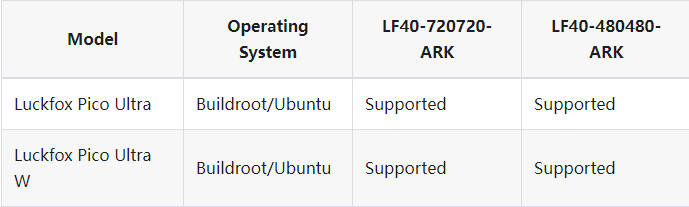
Note: The current development board's Ubuntu 22.04 and Buildroot systems both have screen drivers. However, the lvgl example program currently only supports the Buildroot system.
1. Example Program
Obtain the LVGL example program source code (on a virtual machine or Ubuntu host).
git clone https://github.com/luckfox-eng29/luckfox_lvgl.gitCross-compile the example program.
# Compilation environment: WSL2 Ubuntu 22.02
mkdir build
cd build
export LUCKFOX_SDK_PATH=<absolute path to Luckfox Pico SDK>
cmake ..
make -j- The final compiled executable:
luckfox_lvgl_demo
- The final compiled executable:
Hardware Connection
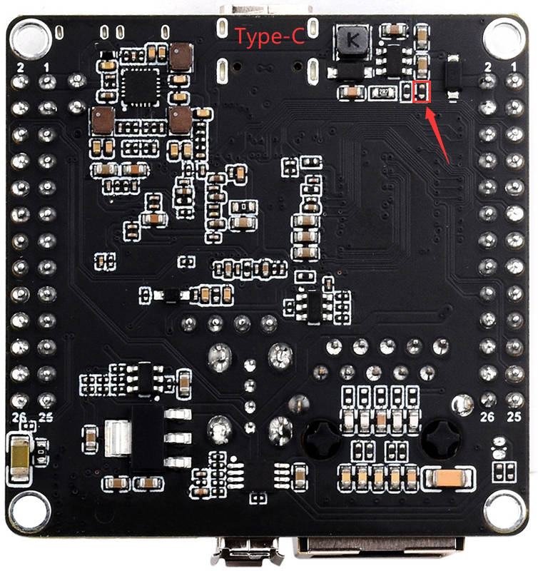
Luckfox Pico Ultra: If connecting to LP40-720720-ARK, check if a resistor is soldered at the following position. If it is, it must be removed. LP40-480480-ARK does not require checking for this resistor. (For versions shipped after July 5, 2024, this resistor will not be soldered by default.)
The screen is not connected to the FFC cable, and the specific connection steps are as follows:
① Lift the black latch on the adapter board upward.
②Insert the FFC ribbon cable with the metal side facing down into the adapter board.
③Lock the latch.
Note: If the screen cannot display properly (e.g., with ripples), check if the FFC cable connection is secure. You may need to reinsert it to ensure proper contact.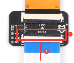
Screen: Connect the screen to Luckfox Pico Ultra as shown in the diagram.
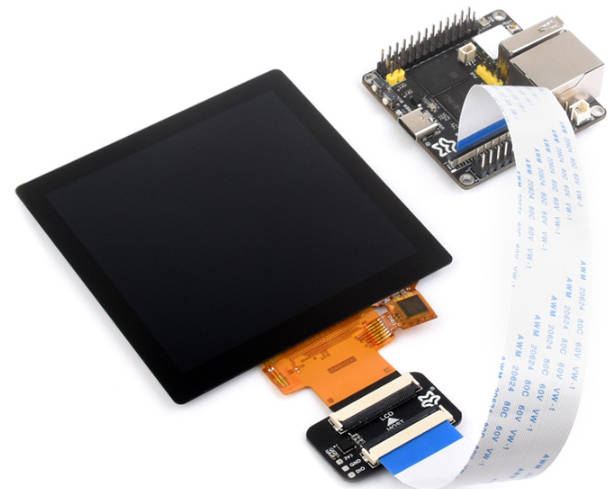
Note: Ensure power is off when connecting the screen. Before powering on, double-check the connection. Incorrect connections may damage the screen or Luckfox Pico Ultra.
Antenna: The LVGL example program can connect to WIFI (Luckfox Pico Ultra W only). A WIFI antenna is required for proper functionality.
- Speaker: The LVGL example program can play music. A speaker is required for audio playback.
- Uploading and running the executable
Use the
adborscpcommand to upload the file to Luckfox Pico Ultra. If you plan to play music, place the.mp3audio files in the/musicfolder (create the folder using themkdircommand if it doesn't exist). The music playback function will not work without the folder or if the folder lacks.mp3files. Due to the defaultRKIPCprogram running on startup occupying the audio, you must force it to close before running the test program.RkLunch-stop.sh
chmod a+x ./luckfox_lvgl_demo
./luckfox_lvgl_demo- Luckfox Pico Ultra LVGL example program main interface
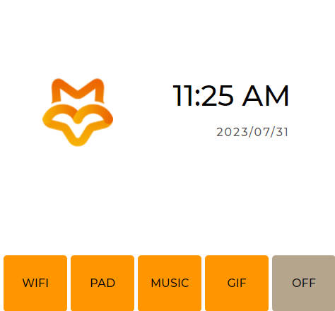
- Luckfox Pico Ultra LVGL example program main interface
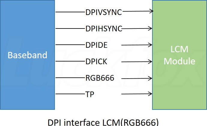
2. MIPI DPI Interface
The RGB interface, also known as DPI (Display Pixel Interface), uses standard synchronization, clock, and signal lines to transmit specific data, with control lines like IIC for command control. The DPI interface signal lines include:
- DPIVSYNC (Vertical Sync): Indicates the start of a frame.
- DPIHSYNC (Horizontal Sync): Indicates the start of a line of pixels.
- DPIDE (Data Enable): Indicates that the currently transmitted data is valid pixel data.
- DPICK (Clock): Pixel clock signal used for synchronizing data transmission.
- Data Lines: Multiple parallel data lines (e.g., DPI_DATA0, DPI_DATA1, ...) for transmitting pixel data.
3. Rockchip Platform Display Subsystem (DSS)
The display subsystem on the Rockchip platform encompasses the hardware and software related to display output. The Linux kernel uses the component framework to build the display subsystem. It includes the video output processor (VOP), interface controllers (MIPI, LVDS, HDMI, eDP, DP, RGB, BT1120, BT656, I8080), LCD backlight, power, and other modules. The RV1106 utilizes VOP1.0, with the hardware framework of the display system illustrated as follows: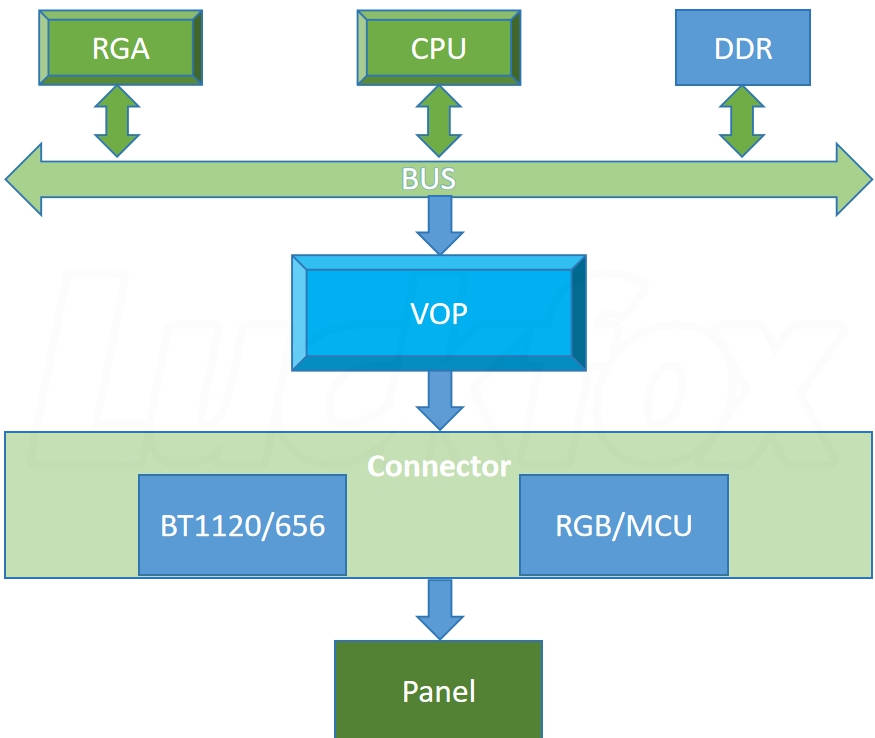
4. FBDEV Introduction
Linux kernel uses two main types of graphics display device driver frameworks: DRM (Direct Rendering Manager) and FBDEV (Framebuffer Device). In the Framebuffer framework, users can directly manipulate the display memory via the /dev/fbX interface for standard file operations (read, write, ioctl). It provides basic 2D graphics operations but lacks support for advanced hardware features like 3D rendering.
5. DRM Introduction
DRM, short for Direct Rendering Manager, manages display output, buffer allocation, and framebuffer. The userspace library libdrm provides user-friendly control and buffer allocation interfaces. The DRM device node is /dev/dri/cardX, with X ranging from 0 to 15.
5.1 Differences between DRM and Framebuffer
The following diagram compares the connection process to the device endpoint for FBDEV and DRM: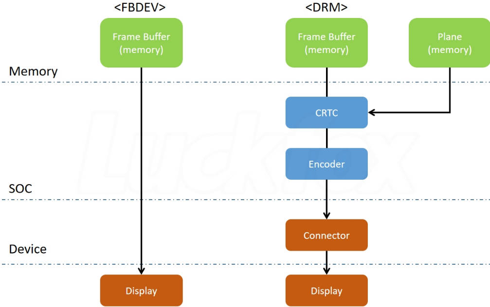
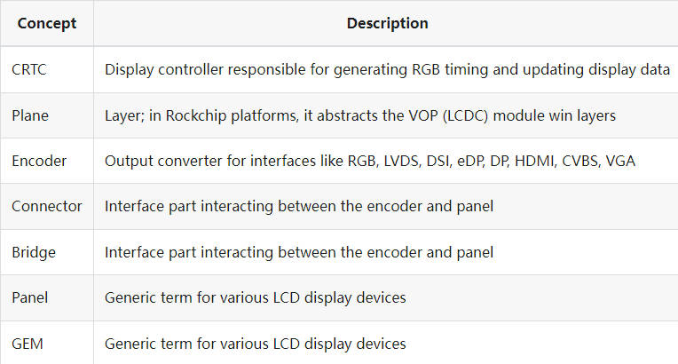
6. Basic DRM Concepts
DRM defines several concepts to manage various hardware modules in the display path:
7. DRM Framework Introduction
Interaction between DRM driver and libdrm: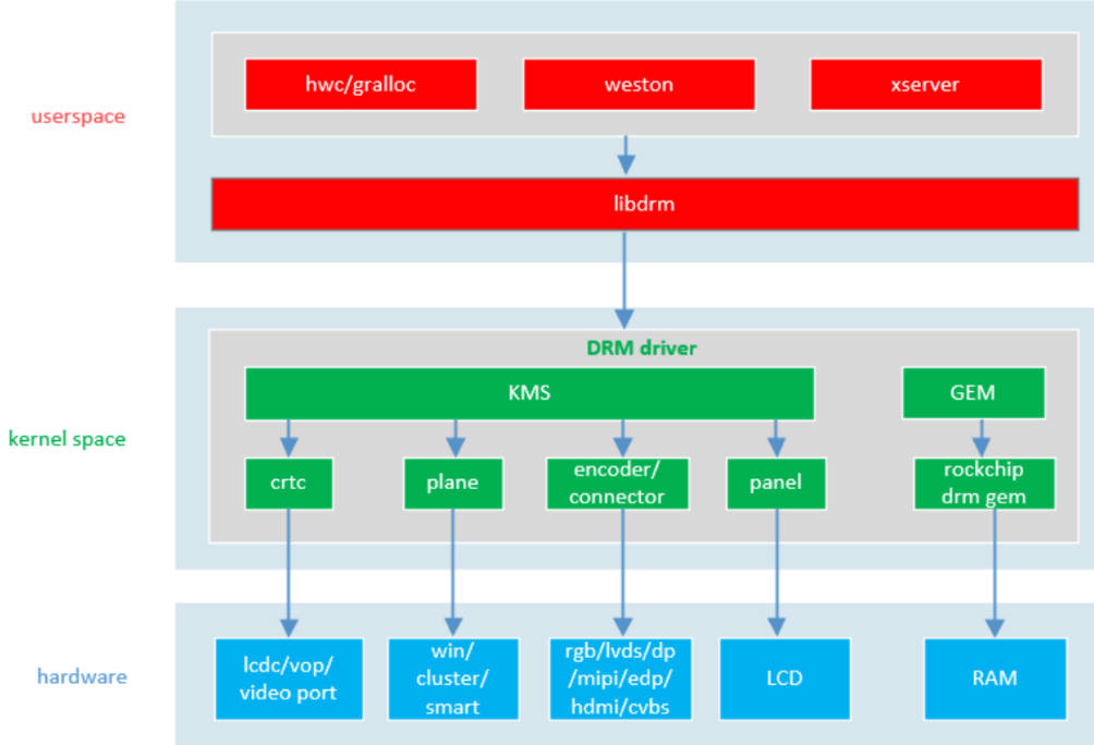
7.1 Libdrm
Libdrm is a userspace library in the DRM framework, providing an interface to the DRM drivers by wrapping various ioctl interfaces.
7.2 KMS
KMS (Kernel Mode Setting) allows the kernel to manage display modes and resolutions directly, improving stability and performance. It includes components like CRTC, Plane, Encoder, and Connector.
7.3 GEM
GEM (Graphics Execution Manager) handles memory allocation and management, ensuring efficient memory operations for graphics data.
7.4 drm_panel
Drm_panel is a set of callback functions that reduce coupling between LCD drivers and encoder drivers, allowing display drivers to interact with display panels.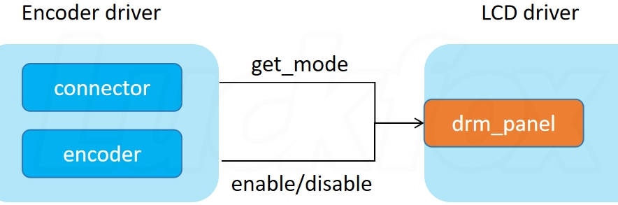
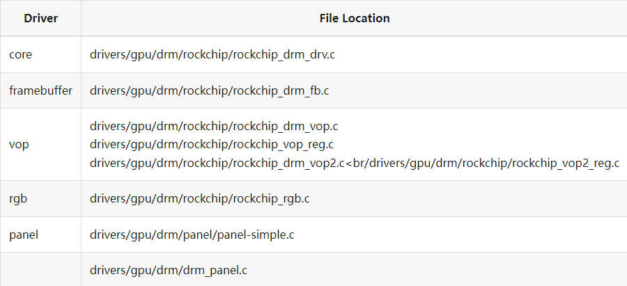
8. Driver Module Path
The Linux kernel places DRM driver-related code in the drivers/gpu/drm directory. The main components include:
9. DRM Driver Entry
Platform driver and device matching is done by comparing the fields in the driver and device to see if they match. Through the
compatibleproperty, the kernel will match thesimple-paneldriver with thepanelnode in the device tree.static struct platform_driver panel_simple_platform_driver = {
.driver = {
.name = "panel-simple",
.of_match_table = platform_of_match,
},
.probe = panel_simple_platform_probe,
.remove = panel_simple_platform_remove,
.shutdown = panel_simple_platform_shutdown,
};The
probefunction of the driver will check thedisplay-timingsnode and parse its timing parameters. Based on the parsed timing parameters, the driver will configure the display controller to ensure the panel can display correctly.static int panel_simple_of_get_desc_data(struct device *dev,
struct panel_desc *desc)
{
struct device_node *np = dev->of_node;
u32 bus_flags;
const void *data;
int len;
int err;
if (of_child_node_is_present(np, "display-timings")) {
struct drm_display_mode *mode;
mode = devm_kzalloc(dev, sizeof(*mode), GFP_KERNEL);
if (!mode)
return -ENOMEM;
if (!of_get_drm_display_mode(np, mode, &bus_flags,
OF_USE_NATIVE_MODE)) {
desc->modes = mode;
desc->num_modes = 1;
desc->bus_flags = bus_flags;
}The panel node defined in the device tree will be detected by the
panel-simpledriver. Thepanel_simple_platform_probefunction reads the panel description from the device tree, and thepanel_simple_probefunction initializes and registers the panel.static int panel_simple_platform_probe(struct platform_device *pdev)
{
struct device *dev = &pdev->dev;
const struct of_device_id *id;
const struct panel_desc *desc;
struct panel_desc *d;
int err;
id = of_match_node(platform_of_match, pdev->dev.of_node);
if (!id)
return -ENODEV;
if (!id->data) {
d = devm_kzalloc(dev, sizeof(*d), GFP_KERNEL);
if (!d)
return -ENOMEM;
err = panel_simple_of_get_desc_data(dev, d);
if (err) {
dev_err(dev, "failed to get desc data: %d\n", err);
return err;
}
}
desc = id->data ? id->data : d;
return panel_simple_probe(&pdev->dev, desc);
}During registration, the
drm_panel_initanddrm_panel_addfunctions initialize the panel and register it with the DRM framework, making it a part of the DRM subsystem for use by other DRM components.void drm_panel_init(struct drm_panel *panel, struct device *dev,
const struct drm_panel_funcs *funcs, int connector_type)
{
INIT_LIST_HEAD(&panel->list);
panel->dev = dev;
panel->funcs = funcs;
panel->connector_type = connector_type;
}
EXPORT_SYMBOL(drm_panel_init);
/**
* drm_panel_add - add a panel to the global registry
* @panel: panel to add
*
* Add a panel to the global registry so that it can be looked up by display
* drivers.
*/
void drm_panel_add(struct drm_panel *panel)
{
mutex_lock(&panel_lock);
list_add_tail(&panel->list, &panel_list);
mutex_unlock(&panel_lock);
}
EXPORT_SYMBOL(drm_panel_add);
The DRM driver module entry function is
rockchip_drm_init, located indrivers/gpu/drm/rockchip/rockchip_drm_drv.c:#define ADD_ROCKCHIP_SUB_DRIVER(drv, cond) { \
if (IS_ENABLED(cond) && \
!WARN_ON(num_rockchip_sub_drivers >= MAX_ROCKCHIP_SUB_DRIVERS)) \
rockchip_sub_drivers[num_rockchip_sub_drivers++] = &drv; \
}
static int __init rockchip_drm_init(void)
{
int ret;
num_rockchip_sub_drivers = 0;
#if IS_ENABLED(CONFIG_DRM_ROCKCHIP_VVOP)
ADD_ROCKCHIP_SUB_DRIVER(vvop_platform_driver, CONFIG_DRM_ROCKCHIP_VVOP);
#else
ADD_ROCKCHIP_SUB_DRIVER(vop_platform_driver, CONFIG_ROCKCHIP_VOP);
...
ADD_ROCKCHIP_SUB_DRIVER(rockchip_rgb_driver, CONFIG_ROCKCHIP_RGB);
...
#endif
ret = platform_register_drivers(rockchip_sub_drivers,
num_rockchip_sub_drivers);
if (ret)
return ret;
ret = platform_driver_register(&rockchip_drm_platform_driver);
if (ret)
goto err_unreg_drivers;
rockchip_gem_get_ddr_info();
return 0;
err_unreg_drivers:
platform_unregister_drivers(rockchip_sub_drivers,
num_rockchip_sub_drivers);
return ret;
}- In the earlier kernel configuration, we enabled
CONFIG_ROCKCHIP_VOPandCONFIG_ROCKCHIP_RGB, so this step adds thevop_platform_driverandrockchip_rgb_driverdrivers to therockchip_sub_driversarray. - Register multiple drivers using
platform_register_driversand registerrockchip_drm_platform_driver.
- In the earlier kernel configuration, we enabled
Platform driver and device matching directly compare driver and device fields to see if they are identical. The
rockchip-drmplatform driver is a DRM driver for Rockchip chips, mainly used to manage and control the display subsystem.static struct platform_driver rockchip_drm_platform_driver = {
.probe = rockchip_drm_platform_probe,
.remove = rockchip_drm_platform_remove,
.shutdown = rockchip_drm_platform_shutdown,
.driver = {
.name = "rockchip-drm", //This field matches the device and driver
.of_match_table = rockchip_drm_dt_ids,
.pm = &rockchip_drm_pm_ops,
},
};of_match_tableis used for device tree matching, matching device nodes withcompatible = "rockchip,display-subsystem":static const struct of_device_id rockchip_drm_dt_ids[] = {
{ .compatible = "rockchip,display-subsystem", },
{ /* sentinel */ },
};The
rockchip_drm_platform_probefunction is called when a platform device matches the platform driver:static int rockchip_drm_platform_probe(struct platform_device *pdev)
{
struct device *dev = &pdev->dev;
struct component_match *match = NULL;
int ret;
ret = rockchip_drm_platform_of_probe(dev);
#if !IS_ENABLED(CONFIG_DRM_ROCKCHIP_VVOP)
if (ret)
return ret;
#endif
match = rockchip_drm_match_add(dev);
if (IS_ERR(match))
return PTR_ERR(match);
ret = dma_coerce_mask_and_coherent(dev, DMA_BIT_MASK(64));
if (ret)
goto err;
ret = component_master_add_with_match(dev, &rockchip_drm_ops, match);
if (ret < 0)
goto err;
return 0;
err:
rockchip_drm_match_remove(dev);
return ret;
}ret = rockchip_drm_platform_of_probe(dev);: Verifies theportsproperty of the display-subsystem device node.match = rockchip_drm_match_add(dev);: Constructs acomponent_matchwith a release function.ret = component_master_add_with_match(dev, &rockchip_drm_ops, match);: Registers an aggregate device and triggersrockchip_drm_ops.bind, i.e.,rockchip_drm_bind, which binds the device and initializes theDRMdriver.
Summary:
- Device Tree Matching: The panel node defined in the device tree is associated with the
panel-simpledriver through device tree matching. At kernel startup, therockchip-drmplatform driver also matches the device tree node. The driver looks for and parses theportsandiommusnodes in the device tree to obtain information about the display pipeline and memory management unit. - Panel Driver Initialization: The
panel_simple_platform_probefunction reads the panel description from the device tree and initializes and registers the panel through thepanel_simple_probefunction. During this process,drm_panel_initanddrm_panel_addare called to initialize and register the panel with the DRM framework. - Registering Components: The
rockchip-drmdriver usescomponent_master_add_with_matchto register itself with the component framework. Therockchip_drm_opsdefines thebindandunbindoperations, which are called during component initialization and unregistration. - Adding Subcomponents: Each subcomponent (e.g., VOP, HDMI, MIPI DSI) is added to the component framework using
component_add. Each subcomponent has a correspondingcomponent_opsstructure defining its ownbindandunbindoperations. - Binding Components: When the master component (
rockchip-drm) matches all subcomponents, it calls itsbindcallback function. This function initializes and configures each subcomponent. - Registering with DRM Core: The
rockchip-drmdriver registers the DRM device when the kernel module loads through thedrm_dev_registerfunction. This function callsdrm_minor_register, which creates character devices and adds them to the/dev/dridirectory, ultimately creating device nodes like/dev/dri/card0.
For more detailed content, enter the source code directory (drivers/gpu/drm) and read the code.
10. RGB Screen System Configuration
10.1 Kernel Configuration
The Luckfox Pico Ultra requires enabling VOP driver support and RGB driver support in the kernel configuration for RGB screen operation (enabled by default).
Open the kernel's menuconfig page under the luckfox-pico SDK root directory
# Ubuntu system
./build.sh kernelconfig
# Ubuntu system
sudo ./build.sh kernelconfig
Search for
CONFIG_DRM_ROCKCHIPby entering "/" and select the first option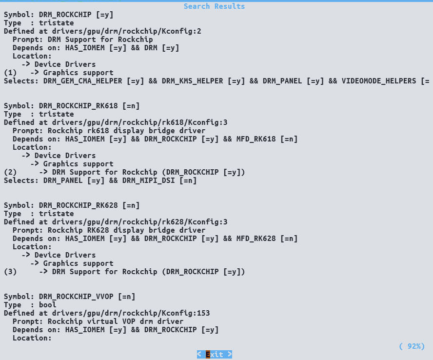
Configure DRM Support for Rockchip, enter "y" to enable
Rockchip VOP driverandRockchip RGB supportDevice Drivers --->
Graphics support --->
<*> Direct Rendering Manager (XFree86 4.1.0 and higher DRI support) --->
<*> DRM Support for Rockchip (DRM_ROCKCHIP [=y])
[ ] Support 3D cubic LUT
[ ] Rockchip DRM debug
[ ] Rockchip DRM direct show
[*] Rockchip VOP driver
[ ] Rockchip VOP2 driver
[ ] Rockchip specific extensions for Analogix DP driver
[ ] Rockchip cdn DP
[ ] Rockchip TVE support
[ ] Rockchip specific extensions for Synopsys DW HDMI
[ ] Rockchip specific extensions for Synopsys DW MIPI DSI
[ ] Rockchip specific extensions for Synopsys DW DPTX
[ ] Rockchip specific extensions for Innosilicon HDMI
[ ] Rockchip LVDS support
[*] Rockchip RGB support
[ ] Rockchip specific extensions for RK3066 HDMI
[ ] Rockchip Virtual connector driver for HDMI/DP/DSI
[ ] Rockchip virtual VOP drm driver< > Synopsis Designware HDCP2 interface
Compile
boot.imgby executing the following command in the luckfox-pico SDK root directory# Ubuntu system
./build.sh kernel
# Ubuntu system
sudo ./build.sh kernelNote: It is recommended to compile and burn
boot.imgafter modifying the device tree for the RGB screen and capacitive touchscreen.
10.2 Device Tree Settings
RGB and VOP Configuration
Relevant device tree settings for RGB display on the Luckfox Pico Ultra are already enabled by default in
<Luckfox Pico Sdk Path>/sysdrv/source/kernel/arch/arm/boot/dts/rv1106-luckfox-pico-ultra-ipc.dtsi.&display_subsystem {
status = "okay";
logo-memory-region = <&drm_logo>;
};
&rgb {
status = "okay";
pinctrl-names = "default";
pinctrl-0 = <&lcd_pins>;
ports {
rgb_out: port@1 {
reg = <1>;
#address-cells = <1>;
#size-cells = <0>;
rgb_out_panel: endpoint@0 {
reg = <0>;
remote-endpoint = <&panel_in_rgb>;
};
};
};
};
&rgb_in_vop {
status = "okay";
};
&route_rgb {
status = "okay";
};
&vop {
status = "okay";
};Note: To disable the use of the RGB screen, change the
statusproperty of the&rgbnode to "disabled" to prevent intended peripheral pins from being reused as LCD pins. When enabling the RGB screen, do not reuse related pins for other functions or connect to other peripherals.CMA Configuration
When using
LF40-720720-ARK, additional10MBmemory needs to be allocated as CMA to display images normally due to insufficient default allocation size of CMA. CMA is allocated from memory, which reduces the available memory size. When not usingLF40-720720-ARK, comment out thereserved-memory/linux,cmanode under<luckfox-pico SDK>/ sysdrv/source/kernel/arch/arm/boot/dts/rv1106-luckfox-pico-ultra-ipc.dtsito release memory resources.
    reserved-memory {
        #address-cells = <1>;
        #size-cells = <1>;
        ranges;
        drm_logo: drm-logo@00000000 {
            compatible = "rockchip,drm-logo";
            reg = <0x0 0x0>;
        };
        //linux,cma {
        //    compatible = "shared-dma-pool";
        //    inactive;
        //    reusable;
        //    size = <0xA00000>;
        //    linux,cma-default;
        //};
    };
Panel Configuration In addition to the default device tree configuration, additional configuration is mainly for the panel node of the screen.
In the latest luckfox-pico SDK, the top-level
dtsfile is already soft-linked toconfig/dts_configunder the luckfox-pico SDK root directory, so modifying it can overwrite the settings indtsiaccording to the model.
LF40-720720-ARKDevice Tree Configuration/**********RGB**********/
&panel {
status = "okay";
reset {
status = "okay";
};
enable {
status = "disabled";
};
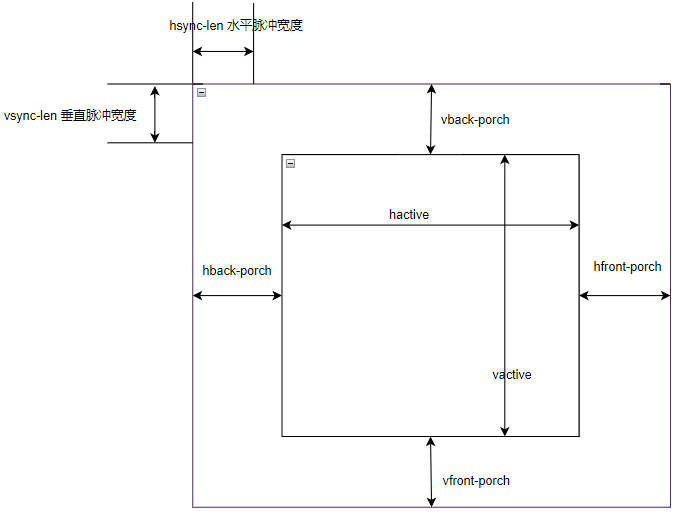
display-timings {
timing0: timing0 {
clock-frequency = <30000000>;
hactive = <720>;
vactive = <720>;
hback-porch = <44>;
hfront-porch = <46>;
vback-porch = <18>;
vfront-porch = <16>;
hsync-len = <2>;
vsync-len = <2>;
hsync-active = <0>;
vsync-active = <0>;
de-active = <0>;
pixelclk-active = <0>;
};
};
};LF40-480480-ARKDevice Tree Configuration/**********RGB**********/
&panel {
status = "okay";
reset {
status = "okay";
};
enable {
status = "disabled";
};
display-timings {
timing0: timing0 {
clock-frequency = <16500000>;
hactive = <480>;
vactive = <480>;
hback-porch = <10>;
hfront-porch = <50>;
vback-porch = <8>;
vfront-porch = <8>;
hsync-len = <4>;
vsync-len = <10>;
hsync-active = <0>;
vsync-active = <0>;
de-active = <0>;
pixelclk-active = <1>;
};
};
};
10.2 DRM Testing
The RGB screen can be controlled using the Framebuffer framework or DRM framework. Use the modetest tool included in the buildroot system to obtain Connector ID and CRTCS ID for DRM display testing.
Luckfox Pico Ultra requires the installation of the modetest tool when using the Ubuntu system (the tool is pre-installed in the buildroot system).
# Ensure that Luckfox Pico Ultra is successfully connected to the network
sudo apt-get update
sudo apt-get install libdrm-dev
sudo apt-get install libdrm-tests
modetest obtains
Connector ID
modetest obtains
CRTCS ID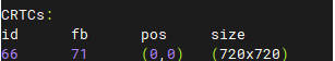
Execute test program to display color blocks.
modetest -M rockchip -s <Connector ID>@<CRTCS ID>:<显示分辨率>Example:
LF40-480480-ARKmodetest -M rockchip -s 70@66:720x720LF40-720720-ARKmodetest -M rockchip -s 70@66:480x480
11. Capacitive Touchscreen System Configuration
Both LF40-720720-ARK and LF40-480480-ARK are equipped with GT911 capacitive touchscreens controlled via I2C.
11.1 Kernel Configuration
When controlling the touchscreen, Luckfox Pico Ultra sets the GT911 touchscreen connected via I2C as an input device, requiring the corresponding driver to be enabled in the kernel.
Enter kernel menuconfig interface under luckfox-pico SDK root directory
# Buildroot system
./build.sh kernelconfig
# Ubuntu system
sudo ./build.sh kernelconfig
Use "/" to search for
TOUCHSCREEN_GOODIX, select the first item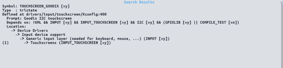
Select
Goodix I2C touchscreen, press "y" to enable it, and save and exit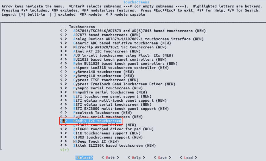
Execute command to compile
boot.imgunder the luckfox-pico SDK root directory.# Buildroot system
./build.sh kernel
# Ubuntu system
sudo ./build.sh kernelNote: It is recommended to compile and burn
boot.imgafter modifying the device tree of RGB screen and capacitive touchscreen.
11.2 Device Tree Settings
GT911 touchscreens will configure different I2C addresses according to power-on timing. After the driver is successfully loaded, communication with GT911 obtains resolution data of the capacitive touchscreen, so the device tree configuration of LF40-720720-ARK and LF40-480480-ARK is consistent.
GT911 Device Tree Configuration
/**********TouchScreen**********/
&i2c3 {
    status="okay";
    clock-frequency = <100000>;
    pinctrl-names = "default";
    pinctrl-0 = <&i2c3m2_xfer &tp_rst &tp_irq>;
    GT911:touchscreen {
      compatible = "goodix,gt911";
      reg = <0x14>;

      interrupt-parent = <&gpio0>;
      interrupts = <RK_PA3 IRQ_TYPE_EDGE_FALLING>;

      reset-gpios = <&gpio0 RK_PA4 GPIO_ACTIVE_LOW>;

  };
};

&pinctrl {
    Touchscreen{
        tp_rst:tp-rst {
            rockchip,pins = <0 RK_PA4 RK_FUNC_GPIO &pcfg_pull_up>;
        };

        tp_irq:tp-irq {
            rockchip,pins = <0 RK_PA3 RK_FUNC_GPIO &pcfg_pull_none>;
        };
    };

};
Note: GT911 touchscreen will occupy
I2C3M2, ensure no other groups of I2C3 are in use.
11.3 Touchscreen Testing
11.3.1 I2C Testing
If the power-on timing is correct, the GT911 touchscreen will be recognized at address 0x14 on I2C3, and the GT911 driver will occupy this address.
Use the i2cdetect command to check the device mounting status of I2C3.
i2cdetect -y 3You can observe that the address
0x14of I2C3 is marked as "UU".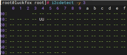
Note: If address
0x14of I2C3 is not recognized, it may be due to incorrect power-on timing or poor contact. Check whether the FPC soft ribbon is installed stably.
11.3.2 hexdump Testing
During GT911 touchscreen driver loading, an event node will be created under /dev/input to transmit touch information. If no other input devices are added to Luckfox Pico Ultra, the GT911 touchscreen node is typically /dev/input/event0.
Luckfox Pico Ultra requires the installation of the hexdump tool when using the Ubuntu system (the tool is pre-installed in the buildroot system
# Ensure that Luckfox Pico Ultra is successfully connected to the network
sudo apt-get update
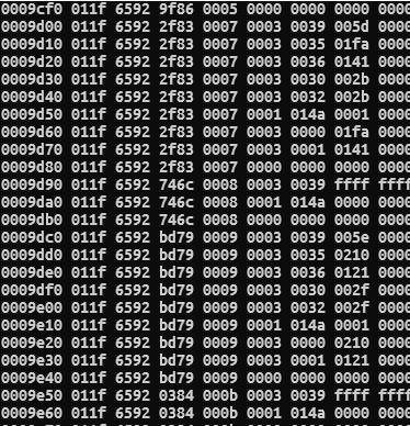
sudo apt-get install bsdmainutilsUse the hexdump command to retrieve GT911 transmission information.
hexdump /dev/input/event0Trigger interrupt by touching the screen with your finger. The printed information is the initial information transmitted by GT911 to the input subsystem, and further processing is required to obtain actual coordinate values.
Note: The adc-key (corresponding to the BOOT button) on Luckfox Pico Ultra is also registered as an event node. If the GT911 touchscreen driver fails to load,
/dev/input/event0corresponds to adc-key; if other input devices are loaded earlier, the GT911 touchscreen may be loaded onto/dev/input/event1or another node.
11.3.3 evtest Testing
If you need to observe actual touch coordinate data and more detailed information about input devices, add the evtest tool to buildroot for testing, making it easier to differentiate between multiple input devices.
Enter the buildroot menuconfig interface under the luckfox-pico SDK root directory.
./build.sh buildrootconfigUse "/" to search for
BR2_PACKAGE_EVTEST, select the first item.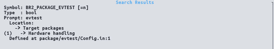
Press "y" to enable
evtest, save and exit.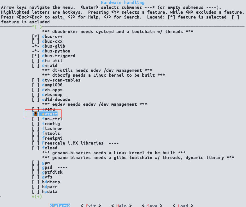
Execute commands to recompile and generate
rootfs.img../build.sh rootfs
./build.sh firmwareBurn the newly generated
rootfs.imginto Luckfox Pico Ultra to use evtest to test input devices.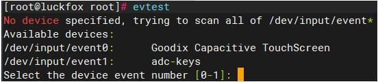
Goodix Capacitive TouchScreencorresponds to the GT911 touchscreen. Select 0 and press Enter to see related information of the GT911 touchscreen device, and touch the screen to observe the triggered event information and coordinate data (ABS_X and ABS_Y).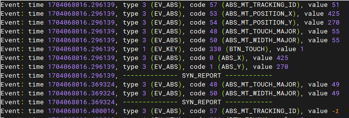
[Tutorial Navigation]
- RGB screen
- Compatible Platforms
- 1. Example Program
- 2. MIPI DPI Interface
- 3. Rockchip Platform Display Subsystem (DSS)
- 4. FBDEV Introduction
- 5. DRM Introduction
- 6. Basic DRM Concepts
- 7. DRM Framework Introduction
- 8. Driver Module Path
- 9. DRM Driver Entry
- 10. RGB Screen System Configuration
- 11. Capacitive Touchscreen System Configuration