


- sales/support
Google Chat:---
- sales
+86-0755-88291180
- sales01
sales@spotpear.com
- sales02
dragon_manager@163.com
- support
tech-support@spotpear.com
- CEO-Complaints
zhoujie@spotpear.com
- Only Tech-Support
WhatsApp:13246739196
- Purchase/Shipping/Refund
WhatsApp:13424403025
LicheeRV Nano User Guide
】Introduction
1. Introduction
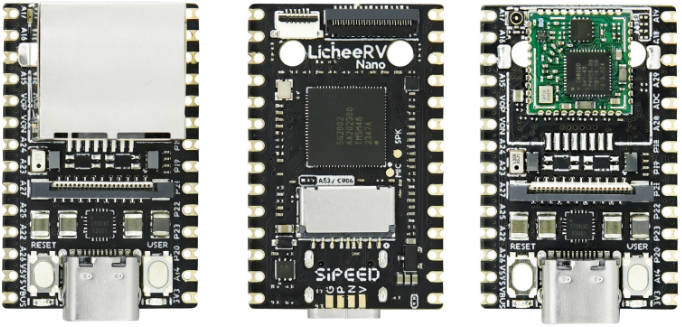
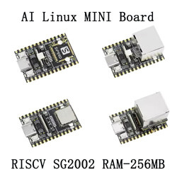
The LicheeRV Nano is a mini-sized development board (measuring only 22.86*35.56mm), equipped with the SG2002 processor. It features a powerful core running at 1GHz (RISC-V/ARM options available) and a smaller core at 700MHz RISC-V, along with 256MB DDR3 memory, and an integrated 1Tops NPU. The board includes a wealth of interfaces such as MIPI-CSI, MIPI-DSI, SDIO, ETH, USB, SPI, UART, I2C, etc., allowing for the expansion of a wide variety of applications. Its through-hole/half-hole design facilitates easy mass production and soldering.
2. Specifications
| Item | Specification |
|---|---|
| CPU | SOPHGO SG2002; Major core: 1GHz RISC-V C906 / ARM A53 (selectable); Minor core: 700MHz RISC-V C906; Low-power core: 25~300M 8051 |
| NPU | 1TOPS INT8, supports BF16 |
| Memory | Integrated 2Gbit (256MByte) DDR3 |
| Storage | Bootable from either TF card / SD NAND (SD NAND pads under TF card slot) |
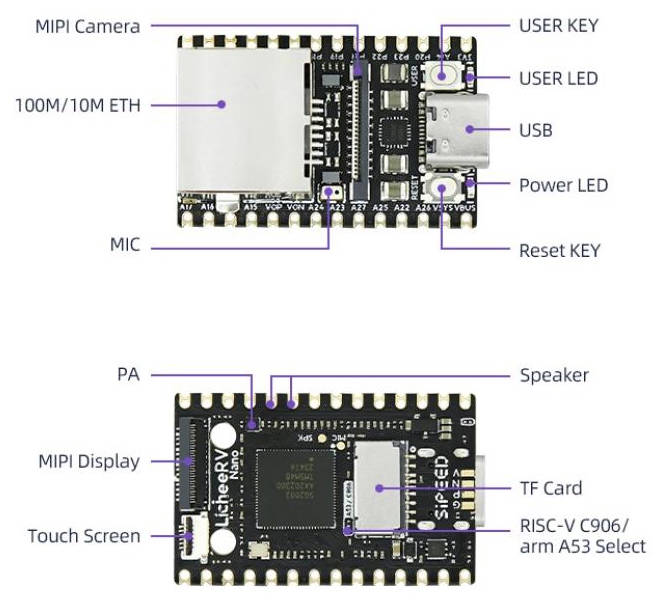
| Video Interface | Video Output: 2 lane MIPI DSI output, standard 31pin interface, supports 6pin capacitive touchscreen Video Input: 4 lane MIPI CSI input, 22Pin interface, supports dual CSI split |
| Audio Interface | Audio Output: Onboard PA amplifier, can directly connect speakers under 1W Audio Input: Onboard analog silicon microphone, capable of direct sound reception |
| Wired Connection | E suffix version supports 100M RJ45 connector |
| Wireless Connection | W suffix version supports 2.4G / 5.8G dual-band WiFi6 + BLE5.4 |
| USB | 1 x USB2.0 OTG Type-C |
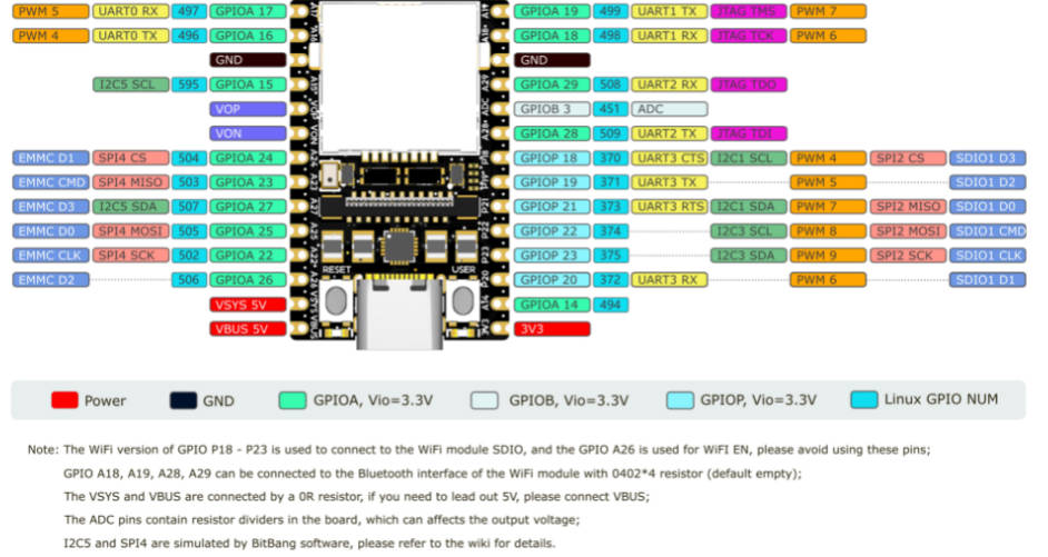
| IO Interface | 2 x 14pin 2.54 pin headers, 800mil spacing, breadboard-friendly |
| Buttons | 1 x RST button + 1 x BOOT button |
| LEDs | 1 x Power LED, 1 x User LED |
| Operating System | Buildroot Linux / Debian |
| Dimensions | 22.86*35.56mm |
3. Version Comparison
| Specification | Basic System | Microphone/Speaker | Ethernet | WiFi6/BT5 |
|---|---|---|---|---|
| LicheeRV-Nano-B | Yes | Yes | No | No |
| LicheeRV-Nano-E | Yes | Yes | Yes | No |
| LicheeRV-Nano-W | Yes | Yes | No | Yes |
| LicheeRV-Nano-WE | Yes | Yes | Yes | Yes |
4. Hardware Resources
Datasheets, schematic diagrams, dimension drawings, and more can be found here: Click
- Board Specification
- Board Schematic
- Board Designator Drawing
- Board Dimensional Drawing
- 3D Model Files
- Core Board Packaging
- Board Chip Information
- http://cn.dl.sipeed.com/shareURL/LICHEE/LicheeRV_Nano/07_Datasheet)
5. Software Resources
6. SOPHGO Resources Summary
- Datasheet
- Compiler Toolchain Download
- Software SDK Download
- SDK Development Documentation Summary
- HDK Development Documentation Summary
- TPU SDK Development Resources Summary
- TDL SDK Development Guide: (Provides common AI model algorithms, application packaging based on TPU SDK)
- TDL SDK Development Resources Summary
- https://developer.sophgo.com/thread/556.html)
- Precautions
】The beta version hardware (70405) NPU only supports operation at 0.5T, running at 1.0T does not guarantee the stability of the board.
】The WIFI of the beta version hardware (70405) has not been fully optimized yet, resulting in lower speeds. We appreciate your understanding.
】If purchasing a camera accessory or the WE version package, screws, soldering pillars, and a screwdriver are included in the package. To avoid burns during soldering, please refer to the Camera & WE Ethernet Module Installation Guide.
】If purchasing 3-inch, 4-inch, or 10.1-inch screen accessories, a screen adapter board and ribbon cable are included in the package. Please refer to the Screen Installation Guide
】Unboxing Experience
1. LicheeRV Nano Package Introduction
The LicheeRV Nano is available in four versions based on networking capabilities:
- Standard Version (B): Comes without any networking accessories.
- Ethernet Version (E): Features an onboard 100M Ethernet port for wired network connections.
- WiFi Version (W): Equipped with an onboard WiFi6/BT5.2 module. By default, the BT5.2 functionality is not enabled. To activate Bluetooth capabilities, it's necessary to solder four 0201 resistors in the specified location or use a 2B pencil to create a short circuit in the designated area.
The WiFi Ethernet (WE) version features an onboard WiFi 6/BT 5.2 module and comes with an Ethernet module that connects to the development board via standoffs and ribbon cables.
We also offer the following accessory:
- Camera
The camera (model 3754) features non-short-circuiting screw holes on both sides for secure mounting. It is recommended to fix the standoffs to the fifth pad for optimal stability.
3-inch Display Screen
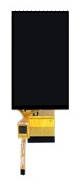
- The display features a resolution of 480*845 and supports touch functionality. The package includes a touch screen adapter board and a ribbon cable for easy integration.
- 5-inch Display Screen
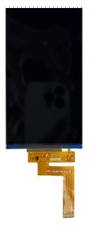
- This display boasts a resolution of 480*845 and does not support touch functionality. The ribbon cable can be directly connected to the LicheeRV Nano 31Pin screen interface for seamless integration.
- 7-inch Display Screen
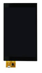
- The display features a resolution of 800*1280 and supports touch functionality. The ribbon cable can be directly connected to both the LicheeRV Nano 31Pin screen interface and the 6Pin touch interface, ensuring easy setup and integration.
- 10-inch Display Screen
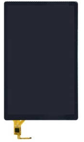
- The display features a resolution of 800*1280 and supports touch functionality. The package includes a touch adapter board and a ribbon cable for easy setup. The screen ribbon cable can be directly connected to the LicheeRV Nano 31Pin screen interface, ensuring seamless integration.
- Raspberry Pi Camera Adapter Ribbon Cable (Coming Soon)
- Raspberry Pi Standard 15Pin Camera to LicheeRV 22Pin CSI Camera Interface Adapter
Installation Guide
1.1. Installing the WE Module
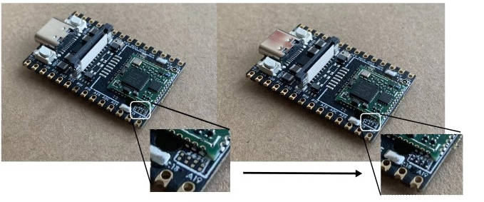
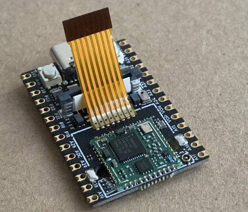
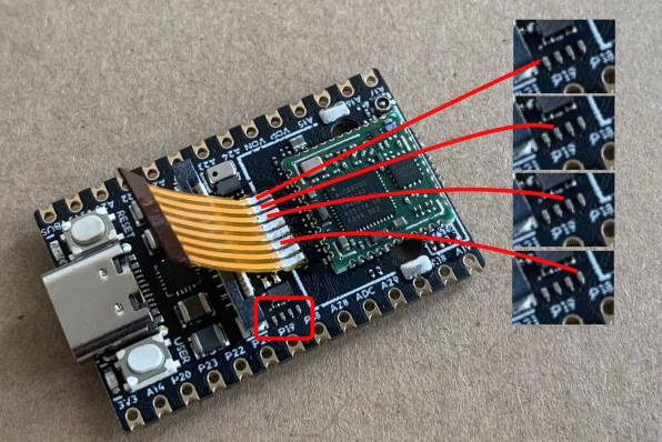
- Soldering the Ribbon Cable
- Solder the ribbon cable following the direction shown in the diagram below.
- Use a Multimeter to Test for Continuity
●Securing the Standoffs
- To avoid burns while soldering the standoffs, you can first screw them onto the Ethernet module.
- Insert the standoff into the fifth pad. It is advisable to apply solder paste to the pad beforehand to enhance the stability of the standoff after soldering.
- Use a soldering iron from the bottom side to solder.
Assembly
- Insert the ribbon cable into the FPC connector of the Ethernet module and secure it.
- Secure the Ethernet module to the standoffs using screws.
1.2. Installing the Camera
- Securing the Standoffs
- Similar to the method mentioned above: first, screw the standoffs and screws onto the camera module.
- Insert the standoff into the fifth pad. To enhance the stability of the standoff after soldering, it is recommended to apply solder paste to the pad beforehand.
- Solder from the bottom side using a soldering iron.
Assembly
- Connect the camera ribbon cable as shown in the diagram below.
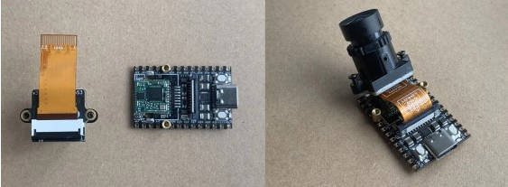
- Secure with screws.
- Connect the camera ribbon cable as shown in the diagram below.
】Image Collection
1. Images Based on the Official SDK
2. Images Based on the Mainline Buildroot SDK (WORK-IN-PROGRESS)
3. Debian Sid Based image
Image Infomation and Downloads
】Flashing the Image
1. Linux
2. Windows
Use 7zip for extraction:
https://www.7-zip.org/download.html
Use Rufus or Win32 Disk Imager to write to the SD card:
https://sourceforge.net/projects/win32diskimager/
】Peripheral
1. Connecting to the Board
1.1. UART0
Connect the UART port to the board at:
A17 A16 GND
Then use terminal software to connect to the serial port, with a baud rate of 115200.
1.2. USB CDC ACM Serial Port
When the board's USB Type-C port is connected to a computer, it will provide a USB CDC ACM serial port device (provided by Linux gadget).
Linux:
Windows:
Press Win + R, enter devmgmt.msc, and press Enter.
Find the new device's serial port number under the serial port devices.
Then use PuTTY or HyperTerminal to connect.
1.3. USB RNDIS Network Port
When the board's USB Type-C port is connected to a computer, it will provide a USB RNDIS network card device (provided by Linux gadget).
The PC will automatically obtain an address using DHCP.
Replace the last digit of the automatically obtained IPv4 address with 1 to get the board's IPv4 address:
Then use ssh to connect: ssh root@board's IP address
Username: root
Password: root
On Windows system, some configurations need to be made.
Open Device Manager and find the following option.
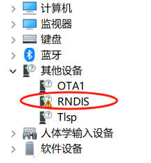
Select "Update driver".
Select "Browse my computer for driver software".
Select "Let me pick from a list of available drivers on my computer".
In the device type list, select "Network adapters".
For manufacturer, select "Microsoft"; for model, select "Remote NDIS Compatible Device".
If this warning pops up, please click "OK".
After the update is successful, it will show as follows.
Then you can find the "Remote NDIS Compatible Device" item under the Network adapters list in Device Manager.
1.4. Ethernet Connection
Connect the Ethernet cable to the board; the board will automatically obtain an address using DHCP upon boot.
The board's image defaults to enabling the MDNS service.
Use the command:
to list devices in the broadcast domain with lpirvnano in their domain names.
Then use:
to connect to the board.
2. Disabling the Boot Demo of the Image
3. Audio
The LicheeRV Nano supports recording and playback. Standard ALSA tools can be used for recording, playback, and other operations.
3.1. Recording
First, set the microphone volume, range: 0-24
After setting, start recording:
3.2. Playback
4. I2C
I2C1 and I2C3 are brought out on the pin header, and devices can be connected to them.
Before using, you need to correctly set the PINMUX:
Then you can use i2c-tools to operate the i2c peripherals. The image is already pre-installed.
5. ADC
An ADC route is brought out on the pin header, using ADC1.
First, select the ADC channel, here taking ADC1 as an example:
Read the value of ADC1:
6. LCD
Connect the screen's ribbon cable to the board's MIPI interface, paying attention to the wire order.
Create or edit the uEnv.txt file in the first partition of the sdcard, add or modify the panel field:
Note: The image will have the first partition already mounted in the /boot directory and can be used directly in the terminal:
7-inch screen:
5-inch screen:
3-inch screen:
2.3-inch screen:
If you want to use the framebuffer function, create a file named fb in the first partition of the sd card:
Then load the driver:
Adjusting the Backlight Brightness:
7. Touch Screen
Connect the touchscreen ribbon to the board's touchscreen interface, paying attention to the wire sequence.
Then execute:
Followed by:
Touching the screen will display specific coordinates in the terminal.
For reading coordinates and touch events, refer to the input section in /opt/src/vendortest.
8. WIFI
Install the antenna onto the WIFI module's antenna connector.
Then write the AP's SSID and password into the /etc/wpa_supplicant.conf file:
After that, execute:
To verify if the network is available:
If available, you can add it to the boot script:
9. Camera
Install the camera onto the camera mount, paying attention to the wire sequence.
Then execute:
When using the 70405 (beta) boards:
10. Button
To view button events, use the command:
Then press the USER button, and you will see the corresponding event report in the terminal.
11. HelloWorld
For information on compiling programs using the vendor's toolchain, visit:
】MMF Deveiopment Guide
1. Overview
This document is used to introduce the method of using SDK to develop MMF, to provide a development idea for developers who want to start developing MMF but can't get started.
MMF full name is Multimedia Framework, an framework that offers a unified API format for video input/output, audio input/output, image signal processing, and hardware encoding/decoding, allowing users to quickly implement multimedia-related functions by calling these APIs.
2. Build MMF development environment
Please refer to the method introduced in LicheeRV Nano->System Development->cvi_mmf_sdk to build the MMF development environment.
Or follow the instructions below:
The above instructions describe how to install the MMF-related compilation environment and how to compile the MMF examples provided by the SDK.
- Note: You may fail to compile sample_cvg. If you do not need this example, try again after deleting the
LicheeRV-Nano-Build/middleware/v2/sample/cvgfolder. If you need this demo, try compiling withbuild_all, which requires compiling the entire SDK, so the compilation time will be longer.
3. Development Document
Please refer to the LicheeRV Nano->Board Introduction to find most of the document.
For MMF applications, pay attention to the following document:
4. Connecting to the Development Board via Network
The purpose of connecting to the development board via network is to upload the firmware we compiled to the board.
Please refer to the methods in LicheeRV Nano->peripheral to get the IP address of the development board. Any one of the three methods can be implemented: Ethernet connection, WIFI connection, or USB RNDIS connection.
5. Compiling and Running an Example
MMF will use the hardware directly, so incorrect operation can lead to system crash, and you must be careful to pay attention to details when developing MMF. The suggestion is to modify your own program by using the examples.
Compile and run sample_vio example:
The instructions above explain how to compile a specific MMF example, and how to upload and run the example on the development board. Developers can modify the example based on their applications to eventually develop the functionality they desire.
6. Have an unsolvable problem?
- Please remain patient and carefully review the development document to see if anything was overlooked. For example, check if the input parameters are correct, whether resources have been properly released, etc.
- Post your problem on maixhub or GitHub. Please organize the functionality you want to achieve, the problems you encountered, the solutions you tried, and the ways to reproduce them, by the way, many times can be solved in the process of organizing your thoughts.
】Support
Monday-Friday (9:30-6:30) Saturday (9:30-5:30) -China time
Email: services01@spotpear.com
[Tutorial Navigation]
- 】Introduction
- 1. Introduction
- 2. Specifications
- 3. Version Comparison
- 4. Hardware Resources
- 5. Software Resources
- 6. SOPHGO Resources Summary
- 】Unboxing Experience
- 】Image Collection
- 1. Images Based on the Official SDK
- 2. Images Based on the Mainline Buildroot SDK (WORK-IN-PROGRESS)
- 3. Debian Sid Based image
- 】Flashing the Image
- 】Peripheral
- 1. Connecting to the Board
- 2. Disabling the Boot Demo of the Image
- 3. Audio
- 4. I2C
- 5. ADC
- 6. LCD
- 7. Touch Screen
- 8. WIFI
- 9. Camera
- 10. Button
- 11. HelloWorld
- 】MMF Deveiopment Guide
- 1. Overview
- 2. Build MMF development environment
- 3. Development Document
- 4. Connecting to the Development Board via Network
- 5. Compiling and Running an Example
- 6. Have an unsolvable problem?
- 】Support