- sales/support
Google Chat:---
- sales
+86-0755-88291180
- sales01
sales@spotpear.com
- sales02
dragon_manager@163.com
- support
tech-support@spotpear.com
- CEO-Complaints
zhoujie@spotpear.com
- Only Tech-Support
WhatsApp:13246739196
- Purchase/Shipping/Refund
WhatsApp:13424403025
Bus-Servo-Driver-HAT-(A) User Guide
Introduction
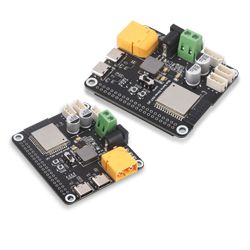
This is a driver board specifically designed for serial bus servos, integrating an ESP32 and serial bus servo control circuits. It features onboard RS485 and TTL serial bus servo interfaces. We have open-sourced the serial bus servo control demos and JSON communication interface. Users can connect via USB and use a host computer to send JSON formatted commands to control the serial bus servos and receive JSON formatted feedback (such as servo torque, speed, position, etc.).
Users can also perform secondary development on it, using it as a slave controller in their robotics projects.
Specification
- Controller: ESP32-WROOM-32
- Power Supply Port: XT60 connector, 5.5×2.5 mm DC jack
- Power Supply: 9~25V (the input voltage and the servo voltage must be matched)
- Communication Interface: UART, USB Type-C port × 2
- Wireless Communication: 2.4G WiFi
- Mounting Hole Diameter: 3 mm
- Mounting Hole Spacing: 58×49 mm
- PCB Size: 65×57 mm
Feature
- Allows controlling up to 253 ST/RSBL series serial bus servos at the same time.
- 9~25V wide voltage input (the input voltage and the servo voltage must be matched).
- Based on the ESP32-WROOM-32 module, supports wired and wireless communication.
- Provides multiple control demos for different host controllers.
- Supports controlling the serial bus servos directly via onboard USB Type-C port.
- Supports connecting to Raspberry Pi, powering the Pi via integrated 5V buck regulator circuit and communicating through GPIO UART interface, neat cable management.
Open-source Project
You can download the relevant open-source robot models in the product literature for building your projects.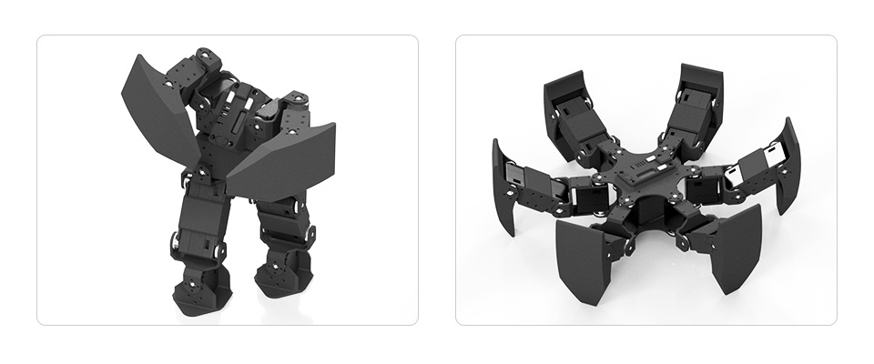
How to Use
Switch to USB Mode
When the driver board is in USB mode, you can use the Python example provided to control the bus servo directly. We will describe the steps to run the Python example in this section.
Python Environment Setup On Windows
First, download the latest installation package from the Python website. Please download it according to your OS. Here the package I downloaded is Python 3.11.5 for Windows.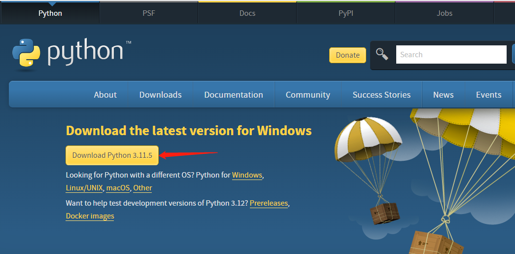
After downloading, double-click python-3.11.5-amd64 to install, and click "Customize installation" to enter "Optional Features". Keep clicking on "Next" to enter the "Advanced Options" interface. Be sure to keep "Add Python to environment variables" checked, and click "Browse" to modify the installation address. Here is the default installation address. Click "Install" after setting, and then just wait for the installation.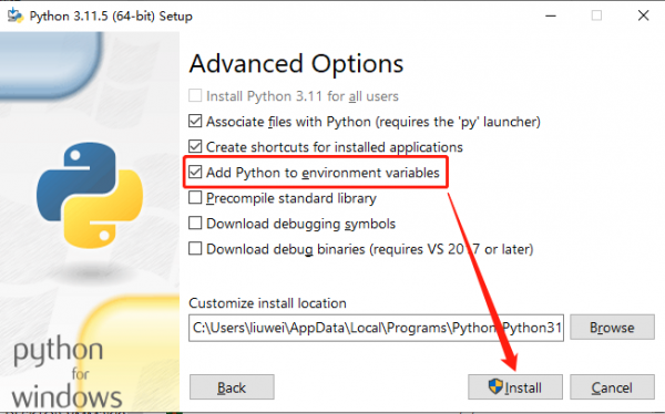
Once installed, let's move on to the Python project compilation example.
ST Series Servo Python Example
Download ST serial bus servo control library (Python) demo, unzip, and then input "cmd" in the start menu bar to open the Windows command prompt interface, type "cd folder path" to enter the STServo_Python project folder, where the virtual environment has been created, the name is stservo-env, and then enter:
stservo-env\Scripts\activate.bat
This command is to activate the virtual environment.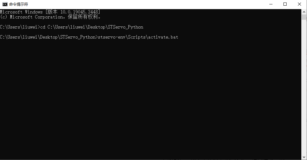
In the STServo_Python project, you can see the "requirements.txt" file, which is for storing the installation package list used in this project. After entering the virtual environment, input:
python -m pip install -r requirements.txt
This command can be used to install the package in this project, and you can see the package to be used only is "pyserial" and has been installed.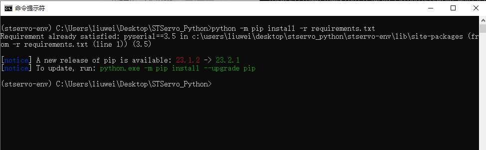
To connect the ST series servos to the serial bus servo interface on the driver board and provide power with a voltage range of 9 to 12.6V, you can search for 'Device Manager' in the Start menu to view the newly connected port number.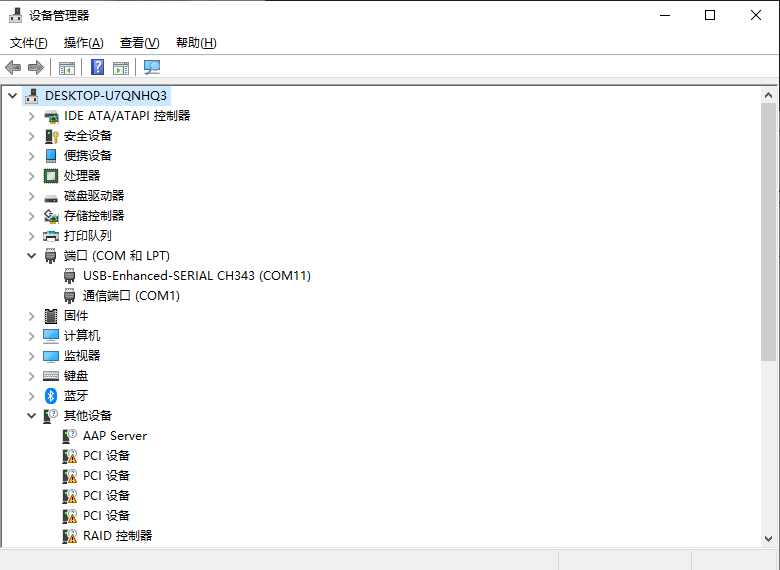
Next, change the name of the device in the demo you want to run to the access port number, in my case COM11 (different computers have different access port numbers).
Once modified you can run it, here is an example of the ping.py file, enter:
python ping.py
You can see it runs successfully and the servo with ID 1 is connected successfully.
These are simple tutorials for Python examples.
Switch to ESP32 Mode
When the driver board is in ESP32 mode, it can be directly controlled by the Web application. When the driver board is powered on, it automatically establishes a hotspot named ESP_DEV for users to connect to, with the password: "12345678", so that you can directly access the IP address of "192.168.4.1" by using the browsers of your cell phone, tablet, or PC to use the WEB application.
Resource
Schematics
Model
Demo
- ST serial bus servo control library (Python)
- ST/SC serial bus servo control library (Arduino IDE)
- ST/SC serial bus servo control library (Linux)
- ST series STM32F103 SDK
- SC series servo sample demo
- ST series servo sample demo
Software
Open-source Structure
Support
Monday-Friday (9:30-6:30) Saturday (9:30-5:30)
Email: services01@spotpear.com