


- sales/support
Google Chat:---
- sales
+86-0755-88291180
- sales01
sales@spotpear.com
- sales02
dragon_manager@163.com
- support
tech-support@spotpear.com
- CEO-Complaints
zhoujie@spotpear.com
- Only Tech-Support
WhatsApp:13246739196
- Purchase/Shipping/Refund
WhatsApp:13424403025
EyeLink-RC-S1 User Guide
Overview
Introduction
EyeLink-RC-S1 is a dual-channel high-definition video transmission mini handheld ground station with a communication distance of up to 15 kilometers, based on fully self-developed low-latency wireless high-definition image transmission technology and deeply integrated with Qualcomm octa-core CPU chip platform. It is feature-rich, performs powerfully, and is widely used in fields such as aircraft and robots.
Features
- 15km wireless digital image transmission range, dual full HD image real-time display
- 5.5inch HD display with 1000-nit high brightness
- Powerful octa-core CPU for high-speed computing
- Supports external HD cameras
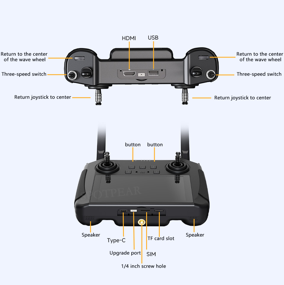
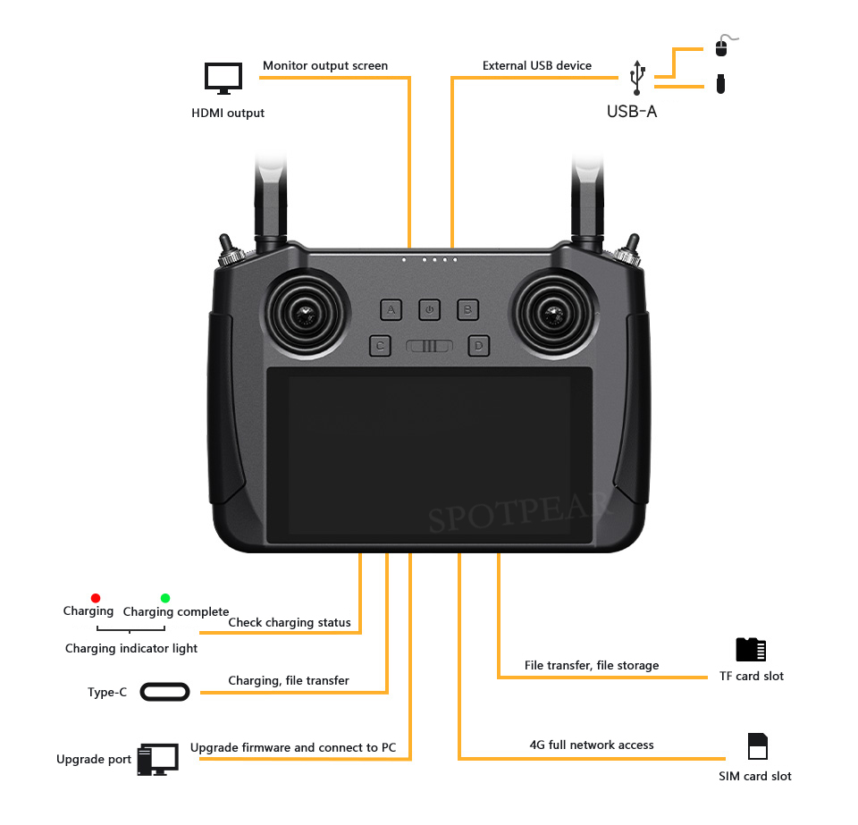
Interface Definition
Interface Definition For Data Stream Connection
Ground Unit Data Stream
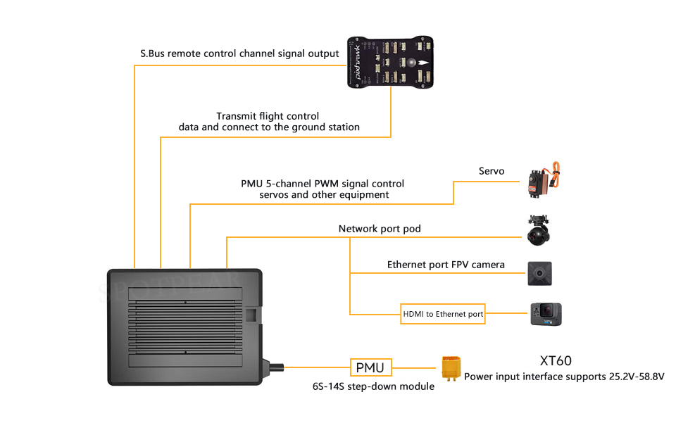
Air Unit Data Stream
Specifications
| Overall Performance | |
|---|---|
| Max Transmission Range (Unobstructed, free of interference) | 15 km |
| Channels | Physical channels: 13 Communication channels: 16 |
| Datalink Compatible Flight Controllers | Open-source flight controllers such as PIX, APM, etc. BOYING Paladin v2 JIYI K3A Pro / K++ VK V7AG |
| Video Stream Compatible GCS | QGroundControl MissionPlanner JIYI IFLY / Agri-Assistant BOYING Agriculture VK V7Pro |
| Ground Unit | |
| Monitor Display | 5.5inch 1080P high definition and high brightness LCD touchscreen |
| System | Android 9.0 OS, 2GB RAM, 16GB ROM |
| Dimensions (Antenna Overlapped) | 189 * 138 * 41 (mm) |
| Weight | 850 g |
| Battery Capacity & Type | 10200mAh, 7.4V 2S Li-ion battery |
| Fast Charging Protocol | PD 20W |
| Charging Time | 5h (PD 20W) |
| Battery Life | 13 H |
| Interface & Ports | Charging: Type-C Firmware upgrade: DATA (4PIN) Mobile network: SIM card slot External storage: TF card slot Tripod mount: 1/4 screw hole Video output: standard HDMI External RTK: DATA (4PIN) External USB Flash Drive: USB-A |
| Waterproof Level | IP53 |
| Working Temperature | -10℃~55℃ |
| Air Unit | |
| Signal Output | 16 channels of S.Bus 5 channels of PWM |
| Interface & Ports | S.Bus: 3PIN Datalink (to FC): UART 4PIN PWM channels 1-5: 6PIN Video input: 8PIN Firmware upgrade: Type-C |
| Dimensions (Antenna Excluded) | 70 × 55 × 16 (mm) (fan included) |
| Weight (Antenna Excluded) | 100g (buck module included) |
| Antenna Gain | 5 dBi |
| Working Voltage | 25.2 ~ 58.8 V (6S ~ 14S) |
| Working Temperature | -10℃~55℃ |
| R1M Recording FPV Camera | |
| Video Output | Ethernet port |
| Image Sensor | 1/2.9 inch 2MP |
| FOV | Diagonal: 90° Horizontal: 80° |
| Working Voltage | 12 V |
| Power Consumption | 2.5 W |
| Video Recording Resolution | 1080p (1920*1080) @ 30 fps 720p (1280*720) @ 30 fps |
| Video Recording Bitrate | 12 Mbps |
| Video Recording Format | MP4 |
| Supported Memory Card Type | MicroSD Class10 Less than 32GB |
| Supported File System | FAT32 |
| Dimensions | 42 x 42 x 25 (mm) |
| Weight | 23 g |
| Working Temperature | -10~50 ℃ |
Product Use
Remote Control
Power On and Off
- Power on: In the off state, short press the power button for about 1 second, the battery indicator light will turn on, then press and hold the power button for about 2 seconds, and when the battery indicator lights up sequentially, you can turn on the remote control and enter working mode.
- Power off: When the remote control is in the on state, press and hold the power button for about 2 seconds. A pop-up window will appear on the system interface. Tap the power off icon to turn off the remote control power.
- Force shutdown: When the power is on, press and hold the power button for about 8 seconds to force the remote power to turn off.
(Other)
- Screenshot: When the power is on, press and hold the power button for about 2 seconds. A pop-up window will appear on the system interface, and tap the screenshot icon to take a screenshot of the Android system interface.
- Screen off: When the power is on, short press the power button to turn off the remote screen and enter energy-saving mode.
Charge
The EyeLink-RC-S1 remote controller only supports charging with the original device manufacturer's standard PD fast charging head while the device is turned off.
1. Connect the EyeLink-RC-S1 remote controller to the PD fast-charging head using a Type-C fast charging cable.
2. If the red charging indicator light is constantly on, it indicates that the device is charging.
3. If the charging indicator light turns green and stays on, it indicates that the charging is complete.
Note
Using a 5V adapter cannot charge the EyeLink-RC-S1 remote controller, please use the original fast charging adapter.
The remote control cannot be charged while it is turned on. Please ensure the remote control is turned off before charging.
Charging Indicator Light Definition
● Red light constantly on: Charging
● Green light constantly on: Charging complete
Switch System Language
The EyeLink-RC-S1 Android system supports almost all available languages, and you can easily switch them in the system settings menu. The default language of the system is Chinese (Simplified).
Steps
1. Enter the Android system settings menu.
2. Scroll down the page to find the "System (Language, Time, Backup, Update)" menu and enter it.
3. Then enter the "Language and input" menu, select "Language", then "Add language".
4. For example, in American English, scroll down to find "English", then select "United States", and the page will automatically return to "Language & Preferences".
5. Drag the newly added "English (United States)" language field to the top position, and the system language will automatically switch to American English.
Important Notes on Enhancing Communication Distance and Video Smoothness
To maximize the range and video fluency of the EyeLink-RC-S1 link, it is important to read this manual carefully and follow the instructions for selecting and installing the antenna, and setting up the link.
Precautions for Use
1. Avoid using FPV applications and RTSP streaming software like QGroundControl simultaneously. Running streams in the background also consumes video transmission bandwidth, which may affect the operating range;
2. Only the power battery is allowed to power the XT60 interface of the EyeLink-RC-S1 air unit, because HD image transmission has high requirements for current, instantaneous current response, and ripple of the power supply. Do not modify the buck module without permission, otherwise it may affect the link stability and image transmission distance. If you do not need the voltage reduction module, it is recommended to use the HM30 air unit.
3. The default settings for FPV applications should be hard decoding, as soft decoding may increase latency.
Antenna Selection and Wireless Flight Mode Setting Methods Under Different Flight Distance Requirements
1. Flight distance within 10 km:
Install two standard omnidirectional antennas for the ground unit, select "5km" or "8km Low Latency FPV Flight Mode" under "System Settings - Wireless Mode" in the remote control application;
2. 10 to 15 km flight distance:
Install two standard omnidirectional antennas or two standard extended range antennas for the ground unit, select "15km Ground Station Flight Mode" under "System Settings - Wireless Mode" in the remote control application;
3. 15 to 30 km flight distance:
Install two standard extended range antennas or higher gain flat panel antennas on the ground unit, select "24km Ground Station Flight Mode" under "System Settings - Wireless Mode" in the remote control application. The flat panel antenna is a directional antenna with directionality, please ensure the flat antenna at the ground unit always faces the aircraft;
4. The top signal of a standard omnidirectional antenna is weak; when flying directly above the ground unit, the aircraft's flight altitude should be as low as possible below 100 meters;
5. When flying with an extended range antenna or flat panel antenna on the ground unit, the aircraft should always be in front of it, not directly above or in the opposite direction;
Installation and Placement of Standard Omnidirectional Antennas on Ground Unit
1. The antenna SMA connector must be tightened;
2. The antenna should be positioned vertically above the control panel on the ground unit, keeping the flat surface of the antenna always facing the aircraft. The antenna must not be stacked or crossed;
3. The recommended spacing between the two standard omnidirectional antennas at the ground unit should be more than 10cm, with a minimum of no less than 5cm; otherwise, it will affect the signal transmission.
Installation and Placement of Flat Panel Extended Range Antennas on Ground Unit
1. The antenna SMA connector must be tightened;
2. The flat panel antenna is a directional antenna with directionality, please ensure the flat antenna at the ground unit always faces the aircraft;
3. When using the original extended range antenna, the short side of the flat antenna shell must be placed parallel to the ground, and the long side must be placed vertically with the ground unit operation panel to achieve the farthest communication distance;
4. The recommended spacing between the two flat panel extended range antennas at the ground unit should be more than 10cm, with a minimum of no less than 5cm; otherwise, it will affect the signal transmission.
Installation and Placement of Standard Omnidirectional Antennas on Air Unit
1. The antenna SMA connector must be tightened;
2. On a multirotor aircraft, the standard omnidirectional antenna on the air unit should be installed vertically downward perpendicular to the airframe plane; on a fixed-wing aircraft, the antenna can be installed vertically upward perpendicular to the airframe plane. Keep the flat side of the antenna facing the ground unit as much as possible during flight;
3. The antenna feedline wiring should be kept away from devices with high-power currents and severe electromagnetic interference, such as electronic speed controllers (ESCs) and motors;
4. The standard 300mm long feedline on the air unit cannot cross. The antenna body, feedline, and SMA connectors should avoid direct contact with metal or carbon fiber structural components and maintain a minimum distance of 10mm;
5. The two antennas on the air unit should be placed as far apart as possible, with a minimum distance of 50mm between them; during flight, avoid obstacles blocking communication between the aircraft and the ground unit;
6. At the connection point between the air unit antenna feedline and the two ends, do not pull forcefully or bend excessively, otherwise it may cause antenna damage; if you need to adjust the antenna angle or orientation, try to bend only the middle part of the feedline.
Support
Monday-Friday (9:30-6:30) Saturday (9:30-5:30)
Email: services01@spotpear.com
[Tutorial Navigation]
- Overview
- Introduction
- Features
- Interface Definition
- Interface Definition For Data Stream Connection
- Specifications
- Product Use
- Remote Control
- Important Notes on Enhancing Communication Distance and Video Smoothness
- Precautions for Use
- Antenna Selection and Wireless Flight Mode Setting Methods Under Different Flight Distance Requirements
- Installation and Placement of Standard Omnidirectional Antennas on Ground Unit
- Installation and Placement of Flat Panel Extended Range Antennas on Ground Unit
- Installation and Placement of Standard Omnidirectional Antennas on Air Unit
- Support