


- sales/support
Google Chat:---
- sales
+86-0755-88291180
- sales01
sales@spotpear.com
- sales02
dragon_manager@163.com
- support
tech-support@spotpear.com
- CEO-Complaints
zhoujie@spotpear.com
- Only Tech-Support
WhatsApp:13246739196
- Purchase/Shipping/Refund
WhatsApp:13424403025
- HOME
- >
- ARTICLES
- >
- Common Moudle
- >
- ESP
ESP32-S3-Touch-LCD-4.3C User Guide
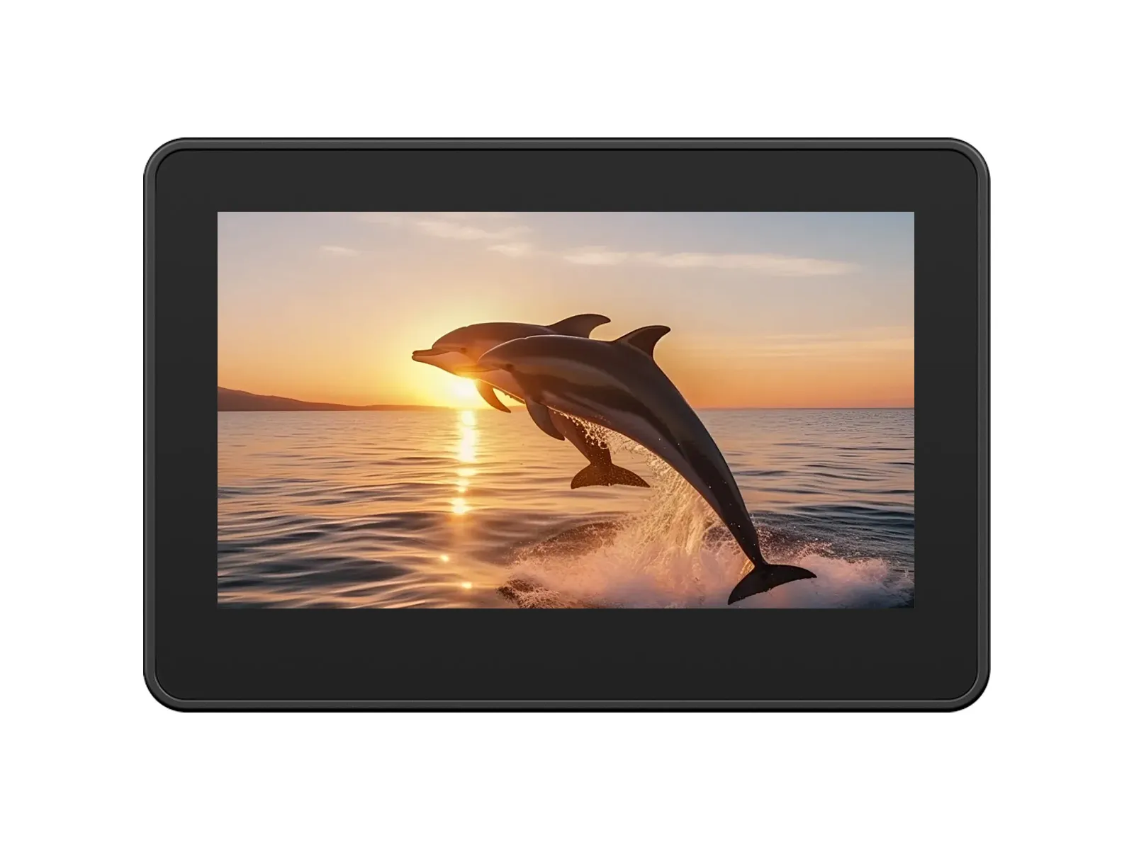
ESP32-S3-Touch-LCD-4.3C
The ESP32-S3-Touch-LCD-4.3C is a low-cost, high-performance development board from Waveshare. It integrates 2.4GHz WiFi, BLE5, large-capacity Flash and PSRAM, and features an onboard 4.3-inch capacitive touch LCD for smooth LVGL GUI operation. It is equipped with an ES8311 audio codec and an ES7210 quad-channel ADC, supporting voice capture and playback. It also provides rich interfaces like I2C and wide-voltage IOs, making it suitable for applications in IoT, mobile devices, and smart homes.
| SKU | Product |
|---|---|
| 33799 | ESP32-S3-Touch-LCD-4.3C (Without case) |
| 33630 | ESP32-S3-Touch-LCD-4.3C (With plastic case) |
Features
- Equipped with the high-performance ESP32-S3R8 featuring an Xtensa® 32-bit LX7 dual-core processor with a clock frequency up to 240 MHz
- Supports 2.4 GHz Wi-Fi (802.11 b/g/n) and Bluetooth® 5 (LE) with an integrated onboard antenna
- Built-in 512KB SRAM and 384KB ROM, with stacked 8MB PSRAM and external 16MB Flash storage
- Onboard 4.3inch wide capacitive touchscreen with 800 × 480 resolution, 65K color
- Supports I2C interface control for capacitive touch, with 5-point touch, and supports interrupts
Onboard Resources
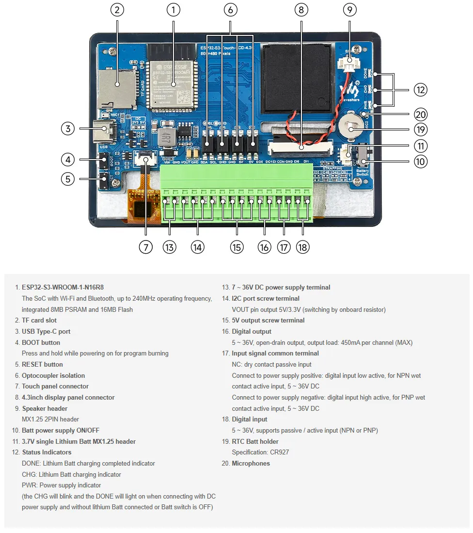
- Onboard PCF85063 RTC Real-Time Clock Chip: Enables timekeeping during power loss and alarm functionality.
- Onboard 4.3inch 800×480 Capacitive Touch LCD Screen: Supports LVGL graphical interface display.
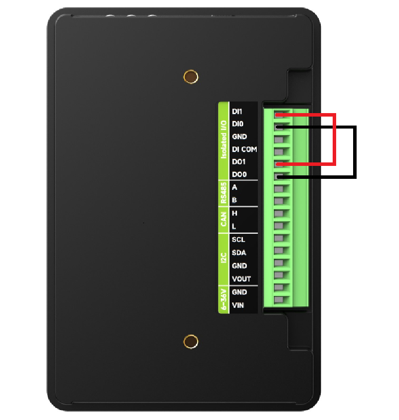
- Onboard Isolation I/O Interface: Provides 2 digital inputs (DI0, DI1) and 2 digital outputs (DO0, DO1) for safe, isolated interaction with external switch devices via the IO_EXTENSION.
- Onboard TF Card Slot: Uses the SD_MMC interface for accessing TF cards to store resources like images and music.
- Onboard ES8311 Audio Amplifier Codec and ES7210 Quad-Channel Audio ADC: Works in conjunction with the speaker and microphone interfaces.
- Onboard USB Type-C Port: Used for firmware downloading, serial log printing, and USB-related debugging. It is the main communication and download channel for Arduino and ESP-IDF examples.
- Onboard BOOT and RST Functional Buttons: Allow quick entry into download mode and resetting to run different firmware.
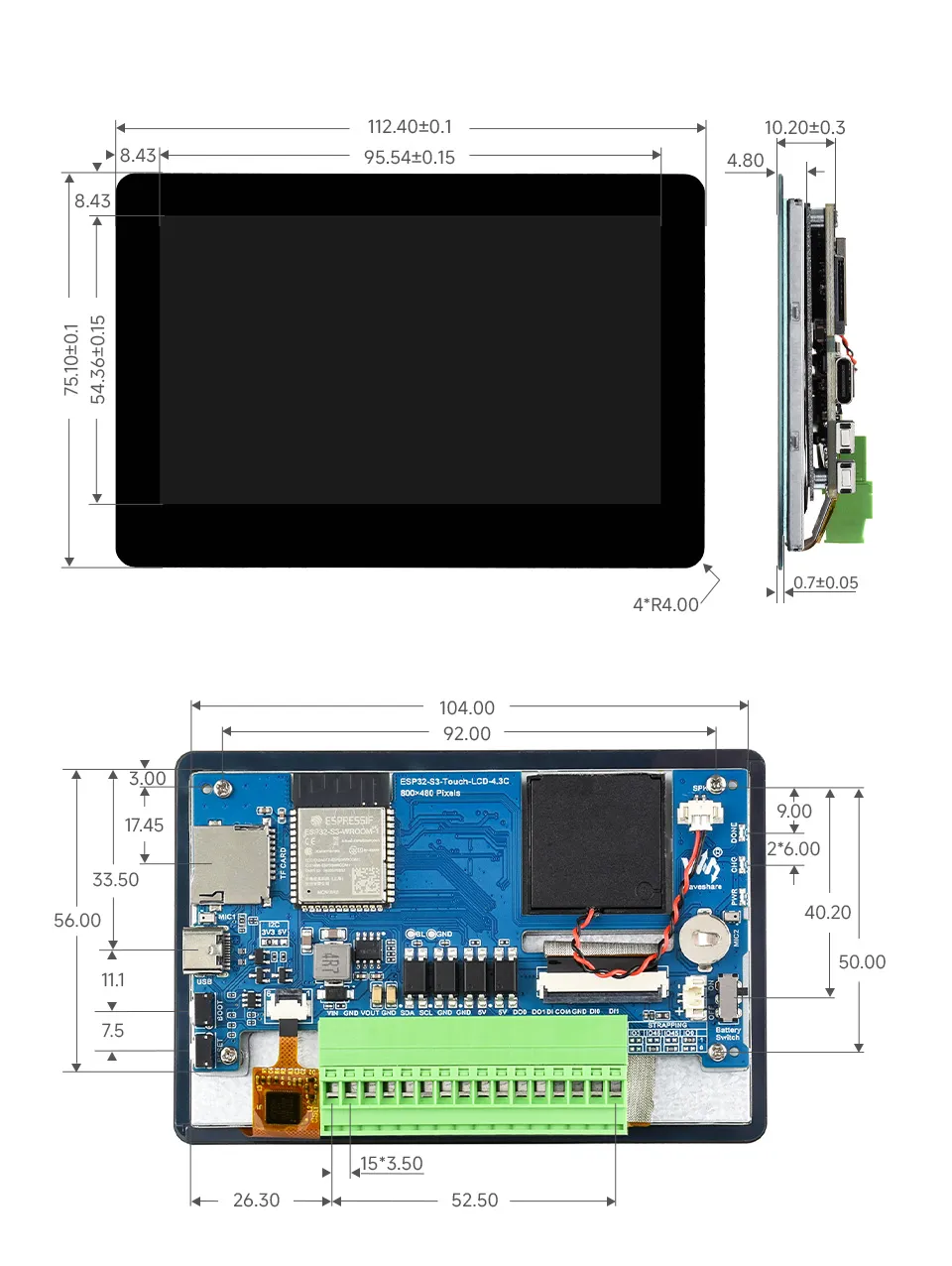
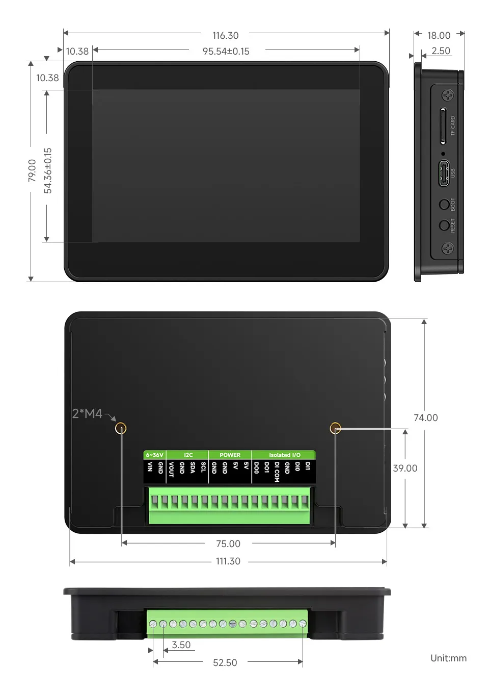
Dimensions
Without Case
With Case
Development Methods
The ESP32-S3-Touch-LCD-4.3C supports two development frameworks: Arduino IDE and ESP-IDF, providing developers with flexible choices. You can select the appropriate development tool based on project requirements and personal preference.
Each method has its advantages, and developers can select based on their needs and skill level. Arduino is simple to learn and easy to get started with, suitable for beginners and non-professionals; ESP-IDF provides more advanced development tools and stronger control capabilities, suitable for developers with professional backgrounds or those with higher performance requirements, and is more suitable for complex project development.
Arduino IDE is a convenient, flexible, and easy-to-use open-source electronics prototyping platform. It requires minimal foundational knowledge, allowing for rapid development after a short learning period. Arduino has a vast global community that provides a wealth of open-source code, project examples, tutorials, and rich libraries that encapsulate complex functionalities, enabling developers to implement various features quickly. You can refer to the Working with Arduino to complete the initial setup, and the tutorial also provides related demos for reference.
ESP-IDF (Espressif IoT Development Framework) is a professional development framework released by Espressif for its ESP series chips. It is developed based on the C language, including a compiler, debugger, and flashing tool, etc. It supports development via command line or an Integrated Development Environment (such as Visual Studio Code with the Espressif IDF plugin), which provides features like code navigation, project management, and debugging, etc. We recommend using VS Code for development. For the specific configuration process, please refer to the Working with ESP-IDF. The tutorial also provides relevant demos for reference.
Working with Arduino
Setting Up Development Environment
1. Installing and Configuring Arduino IDE
Please refer to the tutorial Installing and Configuring Arduino IDE Tutorial to download and install the Arduino IDE and add ESP32 support.
2. Installing Libraries
To run the demo, you need to install the corresponding library.
You can click this link to download the demo package for the ESP32-S3-Touch-LCD-4.3C development board. The
arduino\librariesdirectory within the package already includes all the library files required for this tutorial.Library/File Name Description Version Installation Method lvgl LVGL graphics library v8.4.0 Install via library manager or manually lv_conf.h LVGL configuration file —— Install manually VERSION COMPATIBILITY DESCRIPTIONThere are strong dependencies between versions of LVGL and its driver libraries. For example, a driver written for LVGL v8 may not be compatible with LVGL v9. To ensure stable reproduction of the examples, it is recommended to use the specific versions listed in the table above. Mixing different library versions may cause compilation failures or runtime exceptions.
Installation Steps:
Navigate to the downloaded demo package.
Copy all folders (such as lvgl and lv_conf.h) from the
arduino\librariesdirectory to the Arduino libraries folder.INFOThe path to the Arduino libraries folder is typically:
c:\Users\<Username>\Documents\Arduino\libraries.You can also locate it within the Arduino IDE via File > Preferences, by checking the "Sketchbook location". The library folder is the
librariesfolder under this path.For other installation methods, please refer to: Arduino Library Management Tutorial.
3. Arduino Project Parameter Settings
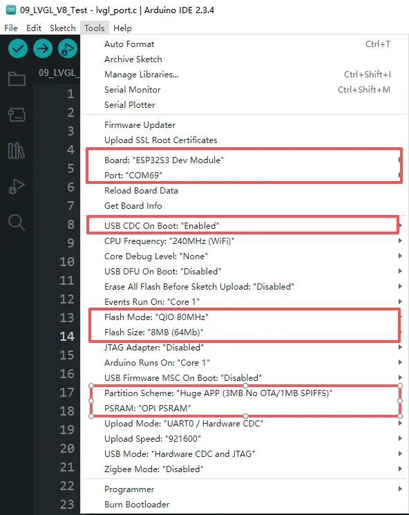
Demo
The Arduino demos are located in the
arduino/examplesdirectory of the demo package.Demo Basic Program Description Dependency Library 01_i2c Test I2C functionality - 02_rtc Test RTC functionality - 03_lcd Test LCD functionality - 04_isolation_io Test ISOLATION_IO functionality - 05_sd Test TF card functionality - 06_touch Test touch screen functionality - 07_display_bmp Display images from TF card - 08_wifi_scan Scan nearby Wi-Fi networks and display names - 09_wifi_sta Test STA mode - 10_wifi_ap Test AP mode - 11_speaker_microphone Test microphone input and speaker playback - 12_lvgl_transplant LVGL demo test LVGL 13_lvgl_btn Draw a button to control GPIO output LVGL 14_lvgl_slider Draw a slider to control backlight & GPIO, display battery voltage LVGL 15_udp_tcp_ntp Implement UDP/TCP communication and NTP time sync LVGL 01_i2c
This example demonstrates how to periodically control the LCD backlight's on/off state via I2C, creating a flashing effect, using an I/O expansion chip.
Hardware Connection
- Connect the board to the computer using a USB cable
Code
01_i2c.ino
Code Analysis
setup():- This function initializes the I2C communication and the I/O expansion chip, setting the IO_EXTENSION_IO_2 pin to output mode.
loop():- The IO_EXTENSION_Output function is used to toggle the IO_EXTENSION_IO_2 pin's state between high (1) and low (0), turning the LCD backlight on and off to create a periodic flashing effect once per second.
Operation Result
- The screen shows nothing, and the connected LED light flashes at a frequency of 1 Hz.
02_rtc
This example demonstrates how to use the onboard PCF85063 RTC chip to implement a real-time clock display and alarm reminder functionality.
Hardware Connection
- Connect the board to the computer using a USB cable
Code
02_rtc.ino
Code Analysis
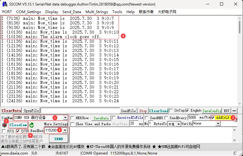
setup():- Initializes the serial port, I2C bus, and the RTC chip, sets the initial time and alarm, preparing the system for operation.
loop():- Continuously reads and prints the current time while checking if the alarm has been triggered, implementing the real-time clock and alarm reminder functionality.
Operation Result
Open the serial port debugging assistant to send a message to the ESP32-S3-Touch-LCD-4.3C device, and the device will return the received message to the serial port debugging assistant
03_lcd
This example demonstrates how to initialize the LCD and display various graphics, text, and images.
Hardware Connection
- Connect the board to the computer using a USB cable
Code
03_lcd.ino
Code Analysis
setup():- Completes LCD initialization, display memory allocation, and sequentially demonstrates the display of color gradients, points and lines, rectangles and circles, text and numbers, and finally images.
Paint_NewImage():- Canvas creation: Sets up memory as the drawing frame buffer.
Paint_DrawRectangle():- Rectangle drawing: Used to draw color stripes, etc.
Paint_DrawString_EN():- Text rendering: Used to draw English character strings. Each function draws different elements, and then wavesahre_rgb_lcd_display() is called to refresh the screen.
Operation Result
- The screen first displays a color gradient bar, followed sequentially by points, lines, rectangles, circles, text, numbers, and finally, two images displayed full-screen.
04_isolation_io
This example verifies the isolation I/O functionality using the display.
Hardware Connection
- Connect the board to the computer using a USB cable
- Connect DO0 -> DI0 and DO1 -> DI1 on the back of the development board.
Code
04_isolation_io.ino
Code Analysis
setup():- The
setup()function initializes the serial port, I2C bus, I/O expansion chip, and LCD screen. It then tests the DI/DO functionality by controlling the DO pins and reading the state of the DI pins. Based on the test result, it displays green (test passed) or red (test failed) on the RGB LCD screen.
- The
Serial.begin(115200):- Initializes serial communication (for printing debug information, baud rate 115200).
DEV_I2C_Init():- Initializes the I2C bus (typically used for connecting sensors, displays, etc.).
IO_EXTENSION_Init():- Initializes the I/O expansion chip (to extend more GPIOs, such as DI/DO).
Operation Result
- After successful flashing, the screen will display red or green depending on the wiring on the back.
- When wired correctly, the screen displays green.
- When wired incorrectly, the screen displays red.
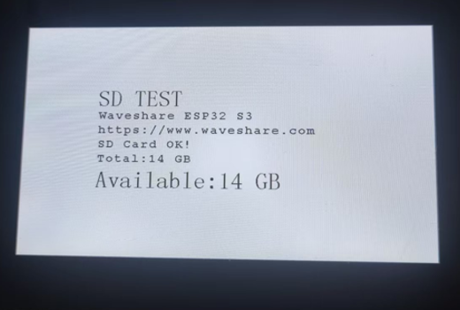
05_sd
This example displays the mounting status of the TF card on the screen.
Hardware Connection
- Connect the board to the computer using a USB cable
- Insert the TF card into ESP32-S3-Touch-LCD-4.3C
Code
05_sd.ino
Code Analysis
setup():- Responsible for initializing all necessary hardware and communication interfaces, including the serial port, I2C bus, I/O expansion chip, and LCD screen. It then performs the TF card test: attempts to mount the TF card, and if successful, reads, calculates, and displays its total and available capacity information on the LCD screen and serial port, before immediately unmounting the TF card.
sd_mmc_init():- Attempts to mount the TF card file system.
read_sd_capacity():- Reads the total and available storage space from the mounted TF card.
sd_mmc_unmount():- Unmounts the TF card file system, releasing related resources.
Operation Result
After successful flashing, the screen displays the TF card capacity. If no TF card is inserted, it displays* TF Card Fail!
06_touch
This example demonstrates how to use 5-point touch.
Hardware Connection
- Connect the board to the computer using a USB cable
Code
06_touch.ino
Code Analysis
setup():- Initializes the serial port, I2C bus, and I/O expansion chip, sets up the touchscreen and LCD screen, and configures double buffering.
touch_gt911_read_point():- Touch reading: Retrieves the coordinates and the number of all valid touch points currently on the screen.
waveshare_rgb_lcd_display():- Displays the content of the buffer onto the screen.
Operation Result
After successful flashing, five-point touch functionality can be achieved.
07_display_bmp
This example demonstrates how to read and display BMP images from a TF card.
Hardware Connection
- Connect the board to the computer using a USB cable
- Insert a TF card containing images into the ESP32-S3-Touch-LCD-4.3C.
Code
07_display_bmp.ino
Code Analysis
setup():- Initializes all hardware and communication interfaces, mounts the TF card, scans for BMP file paths, and contains an infinite loop for continuously reading touch operations and switching between displaying image files from the TF card.
list_files(const char *base_path):- Traverses the root directory of the TF card, finds all
.bmpfiles, and stores their full paths.
- Traverses the root directory of the TF card, finds all
sd_mmc_init():- Mounts the TF card file system.
touch_gt911_init():- Initializes the GT911 touchscreen controller.
GUI_ReadBmp():- Reads the specified BMP file from the TF card and draws it into the frame buffer.
Operation Result
After successful flashing, tapping the left/right navigation arrow areas switches the display to the previous or next BMP image and updates the navigation arrow graphics.

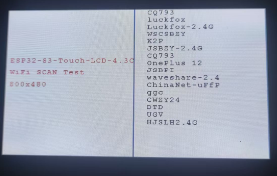
08_wifi_scan
This example demonstrates displaying the names of scanned Wi-Fi networks on the screen (Chinese SSIDs cannot be displayed).
Hardware Connection
- Connect the board to the computer using a USB cable
Code
08_wifi_scan.ino
Code Analysis
setup():- Responsible for initializing all communication interfaces and LCD/Wi-Fi hardware. - Prepares the graphics environment, allocates memory for the buffer. Draws the static UI and performs a single Wi-Fi scan (wifi_scan), directly displaying the list of all found network SSIDs in the right area of the LCD screen.
wifi_scan_init():- Initializes the Wi-Fi hardware and configuration.
wifi_scan():- Performs the actual Wi-Fi scan and directly draws the results onto the LCD screen.
Operation Result
After successful flashing, the scanned Wi-Fi names are displayed on the screen.
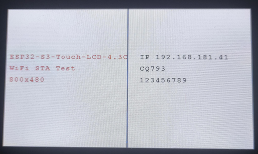
09_wifi_sta
This example demonstrates using the screen to display the IP information after connecting to a hotspot.
Hardware Connection
- Connect the board to the computer using a USB cable
Code
09_wifi_sta.ino
Code Analysis
setup():- Initializes all communication interfaces and LCD hardware, and checks the PSRAM status.
- Allocates the frame buffer, initializes the drawing canvas, and draws the static UI (title, separator line, and "Connecting..." prompt).
- Calls wifi_sta_init(USER_SSID, USER_PASS) to attempt connection to a predefined wireless access point.
wifi_sta_init(USER_SSID, USER_PASS):- Initializes the Wi-Fi module and attempts to connect to the specified SSID and password in Station (STA) mode. A side effect is updating the connection status on the LCD.
Operation Result
After successful flashing, the right side of the screen updates to display the IP address, Wi-Fi name, etc., or a connection failure message after a successful or failed connection.
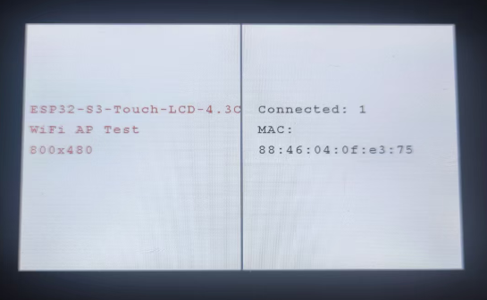
10_wifi_ap
This example demonstrates using the screen to display the status of a hotspot, showing the MAC addresses of connected devices.
Hardware Connection
- Connect the board to the computer using a USB cable
Code
10_wifi_ap.ino
Code Analysis
setup():- Initializes all hardware and the graphics environment, and configures the device as a Wireless Access Point (AP), broadcasting a network with preset SSID and password.
- This function contains an infinite loop: it continuously checks the number of devices connected to the AP. Upon detecting a device connection or disconnection, it clears the status area on the screen and updates the display to show the current connection count and a list of MAC addresses for each connected device.
wifi_ap_init(USER_SSID, USER_PASS):Initializes the Wi-Fi module and configures it into Access Point (AP) mode using the specified network name and password.
wifi_ap_StationNum():- Dynamically updates the right side of the LCD screen to show the number of connected devices.
wifi_ap_StationMac(station_mac, i):- Displays the MAC address of each connected device.
Operation Result
After successful flashing, the Wi-Fi connection count and MAC addresses of devices are displayed.
11_speaker_microphone
This example demonstrates implementing recording and playback functionality via the touchscreen.
Hardware Connection
- Connect the board to the computer using a USB cable
Code
11_speaker_microphone.ino
Code Analysis
setup():- This function initializes all hardware, the touchscreen, LCD, and audio codec, allocates audio buffers, then enters an infinite loop that continuously monitors touch operations to switch between recording and playing back a 5-second audio clip.
play_or_pause(bool play):- Toggles the program state based on the boolean parameter: if true, it reads 5 seconds of audio data from the microphone and stores it in a buffer (recording); if false, it reads data from the buffer and outputs it to the speaker (playback), updating the status and icon on the screen.
codec_init():- Initializes the audio codec (codec_init), sets speaker volume and microphone gain, and configures the audio path.
mic_i2s_read() / speaker_i2s_write():- Called inside the play_or_pause function, used for reading audio data from the microphone and writing audio data to the speaker, respectively.
Operation Result
After successful flashing, tapping the designated area switches between recording and playback operations, enabling both functions.
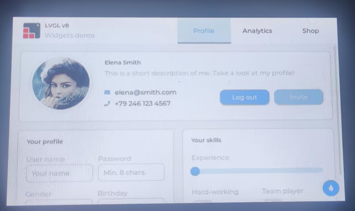
12_lvgl_transplant
This example demonstrates the porting of LVGL.
Hardware Connection
- Connect the board to the computer using a USB cable
Code
12_lvgl_transplant.ino
Code Analysis
setup():- It initializes all hardware (I2C bus, I/O expansion chip) and the GT911 touchscreen, then initializes the Waveshare RGB LCD screen and turns on the backlight. Core functionality: It integrates the LCD and touchscreen handles into the LVGL graphics library (lvgl_port_init), locks the LVGL mutex, and then launches the official LVGL Widgets demo interface (lv_demo_widgets).
lv_demo_widgets():- Starts the LVGL demo: loads and runs the official LVGL-provided Widgets example interface.
Operation Result
After successful flashing, the LVGL sample program is displayed.
Other Notes
- If screen drift occurs during use, please refer to the official ESP FAQ.
- The version of LVGL used is 8.4.0. You can refer to and use the LVGL API via the following documentation:
13_lvgl_btn
Hardware Connection
- Connect the board to the computer using a USB cable
Code
13_lvgl_btn.ino
Code Analysis
setup():- Initializes all hardware (serial port, I2C bus, I/O expansion, GT911 touchscreen) and the Waveshare RGB LCD screen. Core functionality: It integrates the LCD and touchscreen drivers into the LVGL graphics library (lvgl_port_init), then locks the LVGL mutex and calls lvgl_btn() to create and display an interactive button on the screen.
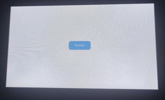
lvgl_btn():- Creates a button object at the center of the LVGL's current active screen. Sets the button's size, position, and label text ("Button"). Binds the btn_event_cb callback function to the button to respond to user interaction.
btn_event_cb(lv_event_t * e):- Triggered when the button is clicked (LV_EVENT_CLICKED). Prints the message "Button Pressed." to the serial port.
Operation Result
After successful flashing, a button will be displayed in the center of the screen. Open the Serial Monitor, and when interacting with the button, the monitor will output "Button Pressed.”.
14_lvgl_slider
Hardware Connection
- Connect the board to the computer using a USB cable
Code
14_lvgl_slider.ino
Code Analysis
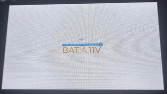
setup():- Initializes all hardware and the Waveshare RGB LCD screen. And integrates the LCD and touchscreen drivers into the LVGL graphics library (lvgl_port_init), then locks the LVGL mutex and calls lvgl_slider() to create and display a user interface containing a slider and voltage labels.
loop():- Takes 10 ADC readings in a loop and calculates their average to reduce noise. Voltage conversion: Converts the average ADC value to an actual voltage.
lvgl_slider():- Creates the main slider, a numeric label displaying the slider value, and a BAT label displaying the battery voltage on the LVGL screen. Simultaneously, it initializes the I/O expansion chip's PWM output to 0 brightness and binds the slider_event_cb to the slider's events.
slider_event_cb(lv_event_t * e):- Triggered when the user drags the slider. It updates the numeric label above the slider and sets the PWM duty cycle (IO_EXTENSION_Pwm_Output) of the I/O expansion chip based on the slider's current value, thereby controlling the LED brightness.
bat_cb(lv_timer_t * timer):- Triggered by the timer created in the loop() function. Updates the battery voltage label (BAT_Label) on the screen using lv_label_set_text.
Operation Result
After successful flashing, a slider control and battery information are displayed. The brightness of the image can be controlled by moving the slider component.
15_udp_tcp_ntp
Hardware Connection
- Connect the board to the computer using a USB cable
Code
15_udp_tcp_ntp.ino
Code Analysis
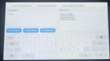
setup():- Initializes the serial port, I2C bus, I/O expansion chip, touchscreen, and LCD hardware, and initializes the LVGL graphics library. Then calls
ui_init()to load the user interface and creates thewifi_connect_tasktask to handle background network connection and time synchronization.
- Initializes the serial port, I2C bus, I/O expansion chip, touchscreen, and LCD hardware, and initializes the LVGL graphics library. Then calls
loop():- Periodically fetches the system's local time and uses
lvgl_port_lockto ensure thread-safe updating of the time display label on the screen.
- Periodically fetches the system's local time and uses
wifi_connect_task():- Responsible for connecting to the Wi-Fi network and synchronizing the system clock via an NTP server once the connection is successful.
Operation Result
After successful flashing, the screen displays system initialization information. After a successful network connection, it will retrieve and continuously update the display with the current date and time via NTP.
Working with ESP-IDF
Setting Up Development Environment
NOTEThe following instructions focus on Windows 10/11. For macOS / Linux, please refer to the official Espressif guide: https://docs.espressif.com/projects/esp-idf/en/latest/esp32/get-started/index.html
Install Visual Studio Code: https://code.visualstudio.com/
Install the
ESP-IDFextension in VS Code (open Extensions view with Ctrl+Shift+X, search for ESP-IDF and install).After installation, an Espressif icon will appear in the sidebar. Open it and select
Configure ESP-IDF Extensionto enter the configuration wizard.The Express configuration is recommended. Choose as needed:
- Download server: Espressif (domestic mirror) or GitHub
- ESP-IDF version: Select based on project requirements; if no specific requirement, choose the latest stable version. Note: Some examples have been tested on older/specific IDF versions.
- Install path: Use a path without spaces and containing only ASCII characters (e.g., C:\Users<Username>\esp) to avoid path-related issues.
Click
Installto begin the automatic download and installation of ESP-IDF, the toolchain, and the creation of a Python virtual environment. Wait for the installation completion prompt.
WARNINGIf installation fails or a reinstall is needed, you can try deleting the
C:\Users\%Username%\espandC:\Users\%Username%\.espressiffolders and then retry.Demo
The ESP-IDF demo package is located in examples/esp-idf.
Below is the purpose, key points, and operation effect for each example (for quick start).
Demo Basic Program Description Dependency Library 01_i2c Uses I2C to control an I/O expansion chip, periodically switching the LCD backlight on and off to create a flashing effect - 02_rtc Uses the onboard RTC chip to implement real-time clock display and alarm reminder functionality - 03_lcd Initializes the LCD and displays various graphics, text, and images - 04_isolation_io Verifies the isolation I/O functionality via the display - 05_sd Displays the TF card mounting status on the screen - 06_touch Demonstrates how to use 5-point touch - 07_display_bmp Shows how to read and display BMP images from a TF card. - 08_wifi_scan Scans nearby Wi-Fi networks and displays the SSID list on the screen - 09_wifi_sta Connects to an AP in STA mode and displays IP information - 10_wifi_ap Uses the screen to display hotspot status, showing the MAC addresses of connected devices - 11_speaker_microphone Recording and playback example (codec, I2S) - 12_lvgl_transplant Ports LVGL and runs the official demo LVGL 13_lvgl_codec Example combining LVGL and audio LVGL 14_tcp_udp_ntp Demonstrates TCP/UDP communication and NTP time synchronization LVGL 01_i2c
This example demonstrates how to periodically control the LCD backlight's on/off state via I2C, creating a flashing effect, using an I/O expansion chip.
Hardware Connection
- Connect the board to the computer using a USB cable
Code
Details
Code Analysis
- DEV_I2C_Init(): Initializes the I2C driver. Defines the SDA/SCL pins and frequency via the
i2c_config_tstructure, and callsi2c_driver_installto register the driver. - IO_EXTENSION_Init(): Initializes the I/O expansion chip, internally configuring the chip's default register states and pin modes via the I2C interface.
- IO_EXTENSION_Output(): Sends control commands to the expansion chip using
i2c_master_write_to_device, modifying the level state of specific pins using bitwise operations.
Operation Result
- The backlight toggles on and off at a fixed interval; the serial port can output the current backlight state or I2C read/write results.
02_rtc
This example demonstrates time reading/writing and alarm functionality of the onboard
PCF85063.Hardware Connection
- Connect the board to the computer using a USB cable
Code
Details
Code Analysis
- PCF85063A_Init(): Initializes the PCF85063A real-time clock, configures the I2C address, enables the oscillator, and sets it to 24-hour mode.
- PCF85063A_Set_All(): Sets all PCF85063A register values, including time, alarm time, control registers, etc.
- PCF85063A_Read_now(): Reads the current time from the PCF85063A, converting BCD-encoded values to decimal format.
Operation Result
The serial port or screen displays the current time; outputs a prompt message when the alarm triggers.
03_lcd
This example demonstrates LCD initialization and basic drawing processes, verifying the
RGB LCDdisplay link and frame buffer refresh.Hardware Connection
- Connect the board to the computer using a USB cable
Code
Details
Code Analysis
- waveshare_esp32_s3_rgb_lcd_init(): Calls
esp_lcd_new_rgb_panelto create a panel handle, configuring RGB interface timing parameters to match the 4.3inch screen's resolution. - malloc(): Allocates the Framebuffer in external PSRAM using the
MALLOC_CAP_SPIRAMflag, addressing the high memory footprint issue for high-resolution displays on SRAM. - Paint_NewImage(): Binds the allocated display coordinates with the drawing context.
Operation Result
- The screen sequentially displays a color gradient, basic shapes, and text content.
04_isolation_io
This example verifies the isolation I/O functionality.
Hardware Connection
- Connect the board to the computer using a USB cable;
- Connect the DO/DI pins as described in the example to test the isolation function.
Code
Details
Code Analysis
- IO_EXTENSION_IO_Mode(): Configures the working mode of the expansion chip's pins, e.g., setting specific pins to input mode to read isolated DI signals.
- IO_EXTENSION_Output(): Controls the output pin levels of the expansion chip, e.g., driving the isolated DO port to output high/low levels to control an external relay or load.
- IO_EXTENSION_Read(): Reads the state of the expansion chip's input pins in real-time, used to obtain feedback from external sensors or digital input connected to the isolated DI port.
Operation Result
- After successful flashing, the screen will display red or green depending on the wiring on the back.
- When wired correctly, the screen displays green.
- When wired incorrectly, the screen displays red.
05_sd
This example demonstrates
TF cardmounting, filesystem access, and displays the mounting status and basic information on the screen.Hardware Connection
- Connect the board to the computer using a USB cable;
- Insert a TF/SD card.
Code
Details
Code Analysis
- esp_vfs_fat_sdmmc_mount(): Mounts the TF card to the virtual file system (VFS), allowing access to the FATFS partition using standard POSIX interfaces (e.g.,
fopen). - sd_mmc_init(): Initializes the SDMMC host controller, configures 1-bit or 4-bit bus mode, and sets the operating frequency according to the hardware design.
- esp_vfs_fat_sdcard_unmount(): Unmounts the TF card from the virtual file system, freeing resources and allowing remounting.
Operation Result
The screen indicates successful/failed mounting and displays card capacity, file list, or test file read/write results.
06_touch
This example demonstrates the touch controller driver and
5 5-point touchreading, verifying the mapping between touch coordinates and screen coordinates.Hardware Connection
- Connect the board to the computer using a USB cable;
- Touch the screen with your finger.
Code
Details
Code Analysis
- touch_gt911_init(): Initializes the touch controller, configures the I2C slave address, and triggers a chip self-test via the reset pin.
- touch_gt911_read_point(): Reads the status register to obtain the current number of touch points and sequentially extracts the X/Y coordinate data for up to 5 touch points.
- Paint_DrawCircle(): Draws a circle with a specified radius and color at the given coordinates.
Operation Result
After successful flashing, 5-point touch reading is demonstrated, and circles are drawn in real-time based on the touch point coordinates.
07_display_bmp
his example reads
BMPfiles from a TF card and displays them on the screen, verifying the file reading, decoding, and display refresh pipeline.Hardware Connection
- Connect the board to the computer using a USB cable;
- Insert a TF/SD card containing BMP files.
Code
Details
Code Analysis
- GUI_ReadBmp(): Reads a BMP file from the TF card, parsing the file header to obtain image dimensions and pixel data offset.
- Paint_Clear(): Clears the canvas, filling it with a specified color.
- Paint_DrawLine(): Draws a line between specified coordinates, allowing configuration of color, line width, and style.
Operation Result
BMP images from the TF card are displayed on the screen; the serial port outputs image information and loading time.
08_wifi_scan
This example scans for nearby Wi‑Fi hotspots and displays information such as
SSID,RSSI, andencryption typeon the screen.Hardware Connection
- Connect the board to the computer using a USB cable;
- Ensure there are Wi‑Fi networks nearby that can be scanned.
Code
Details
Code Analysis
- wifi_init(): Initializes the Wi-Fi driver, allocates resources, and starts the low-power radio management task.
- wifi_scan(): Initiates the scan process for surrounding access points, supporting full-channel polling or specific channel scanning, and configures the maximum number of results to return.
- contains_chinese(): Checks if a string contains Chinese characters, returning
trueorfalse.
Operation Result
- The screen lists information about nearby hotspots; the serial port outputs the scan count and brief data for each AP.
09_wifi_sta
This example connects to a specified AP in
STAmode and displays the connection status andIPinformation on the screen.Hardware Connection
- Connect the board to the computer using a USB cable;
- Have a connectable Wi‑Fi network ready (SSID/password).
Code
Details
Code Analysis
- nvs_flash_init(): Initializes Non-Volatile Storage (NVS), used for persistently saving Wi-Fi connection configurations (such as SSID and password).
- wifi_sta_init(): Configures Wi-Fi to Station (STA) mode, sets authentication/encryption methods (e.g., WPA2_PSK), and initiates a connection request.
- wifi_init(): Initializes the Wi-Fi driver, allocates resources, and starts the low-power radio management task.
Operation Result
The screen displays a successful connection and the assigned IP address; prompts reconnection status upon disconnection.
10_wifi_ap
This example enables a
SoftAPhotspot and displays information about connected devices (e.g.,MACaddress, connection count) on the screen.Hardware Connection
- Connect the board to the computer using a USB cable;
- Connect a phone/computer to the development board's hotspot.
Code
Details
Code Analysis
- wifi_ap_init(): Initializes the Soft Access Point (SoftAP) mode, sets the SSID, password, and operating channel, and configures the maximum number of connected clients.
- esp_wifi_ap_get_sta_list(): Periodically queries the list of connected stations to obtain the current number of connected devices and their hardware MAC addresses.
- MACSTR/MAC2STR(): Uses formatting macros to convert a 6-byte raw MAC address into a human-readable string format for display on the UI.
Operation Result
- The screen displays hotspot status and information of connected devices; the serial port simultaneously outputs connection/disconnection logs..
11_speaker_microphone
This example demonstrates the audio capture and playback pipeline, including
microphone recordingandspeaker playback(Codec + I2S).Hardware Connection
- Connect the board to the computer using a USB cable;
- Record audio via the onboard microphone and play it back through the speaker.
Code
Details
Code Analysis
- codec_init(): Initializes the audio codec chip, configuring the sampling frequency, bit width, and input/output routing (e.g., enabling microphone gain and speaker amplifier).
- heap_caps_malloc(): Allocates a large-capacity recording buffer in PSRAM, supporting long-duration audio capture without exhausting internal SRAM.
Operation Result
Playback audio can be heard; the serial port outputs recording/playback status and audio parameters.
12_lvgl_transplant
This example completes the basic
LVGLport, verifies the display driver, touch input, and LVGL refresh pipeline, and runs the official demo.Hardware Connection
- Connect the board to the computer using a USB cable;
- Touchscreen interaction is possible.
Code
Details
Code Analysis
- lvgl_port_init(): Encapsulates the initialization of LVGL core components, including memory pool allocation, timer registration, and abstract binding of display/input devices.
- lvgl_port_lock(): Since core LVGL APIs are not thread-safe, this mutex lock ensures atomic operations when updating the UI across tasks.
- lv_timer_handler(): The main UI loop handler function, responsible for calculating animations, refreshing dirty pixel regions, and processing user input events.
Operation Result
- The screen displays the LVGL demo interface with touch interaction; the serial port outputs LVGL initialization and refresh information.
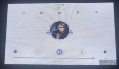
13_lvgl_codec
This example combines the
LVGL UIwith audio functionality, demonstrating interactions such as UI control of volume/playback status.Hardware Connection
- Connect the board to the computer using a USB cable;
- The speaker and microphone should be functional.
Code
Details
Code Analysis
- sd_mmc_init(): Initializes the SDMMC controller and mounts the FATFS partition for retrieving and loading MP3 music files from the TF card.
- speaker_player_init(): Creates a background audio playback task, implementing streaming decoding and playback of audio files via a producer-consumer model.
- lv_obj_add_event_cb(): Binds interaction callbacks to UI controls; when the user operates sliders or buttons, the player state is dynamically adjusted through a messaging mechanism.
Operation Result
The screen displays an audio control interface that can be operated; playback status and volume changes take effect in real-time.
14_tcp_udp_ntp
This example demonstrates basic network communication (
TCP/UDP) and theNTPtime synchronization process, verifying the network stack and time sync functionality.Hardware Connection
- Connect the board to the computer using a USB cable;
- Ensure Wi‑Fi is connected first.
Code
Details
Code Analysis
- peripheral_init(): Serves as the main entry point for initializing system peripherals. It sequentially completes the initialization of NVS, the event loop, I2C expansion, LCD/touch, LVGL UI, Wi‑Fi, and NTP, laying the groundwork for subsequent network communication and time synchronization.
- wifi_init_sta(): Configures Wi‑Fi in STA mode and initiates a connection, providing a stable network channel for TCP/UDP communication and NTP time synchronization.
- initialize_sntp(): Starts the SNTP client after confirming Wi‑Fi is connected, synchronizing the system time from an upstream NTP server to provide a correct base time for time-related interfaces like
localtime.
Operation Result
The serial port outputs connection information; basic data interaction is possible using a network debug assistant set to the corresponding IP address and port number; the screen displays network status and the current time.
Using Factory Firmware
Program Usage
A brief explanation of the usage and functionality of each program.
PREPARATIONFor the image display and music playback tests, you need to copy the two folders from
.\firmware\sdcardto the TF card. The TF card's file system must be formatted as FAT32; otherwise, clicking the icon will restart the system.squareline
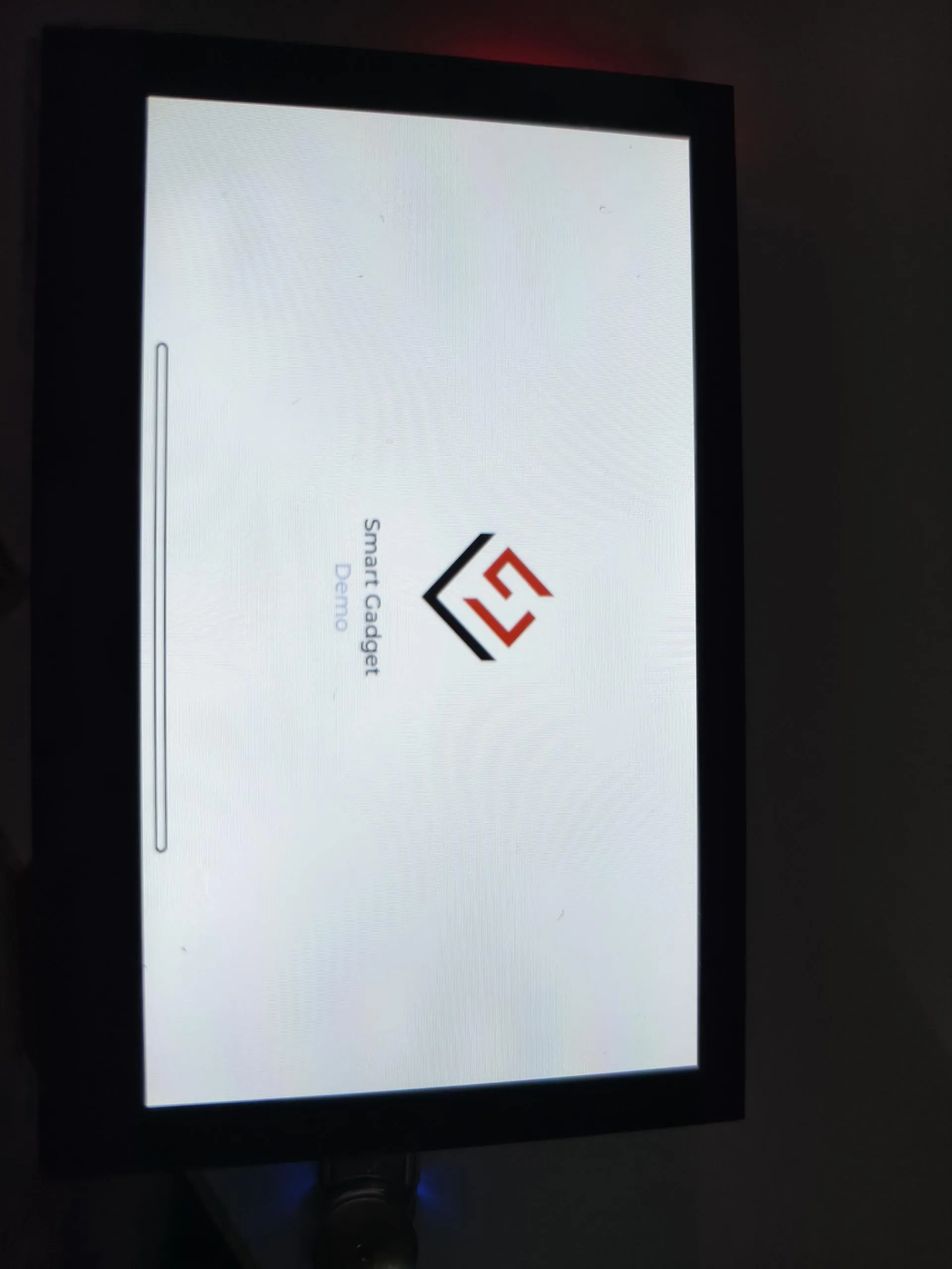
This example directly runs a squareline demo.
Operation Result
DrawPanel
This example tests if the touchscreen is functioning properly.
Operation Result
Gallery
This example reads and displays image files from the TF card.
Operation Result
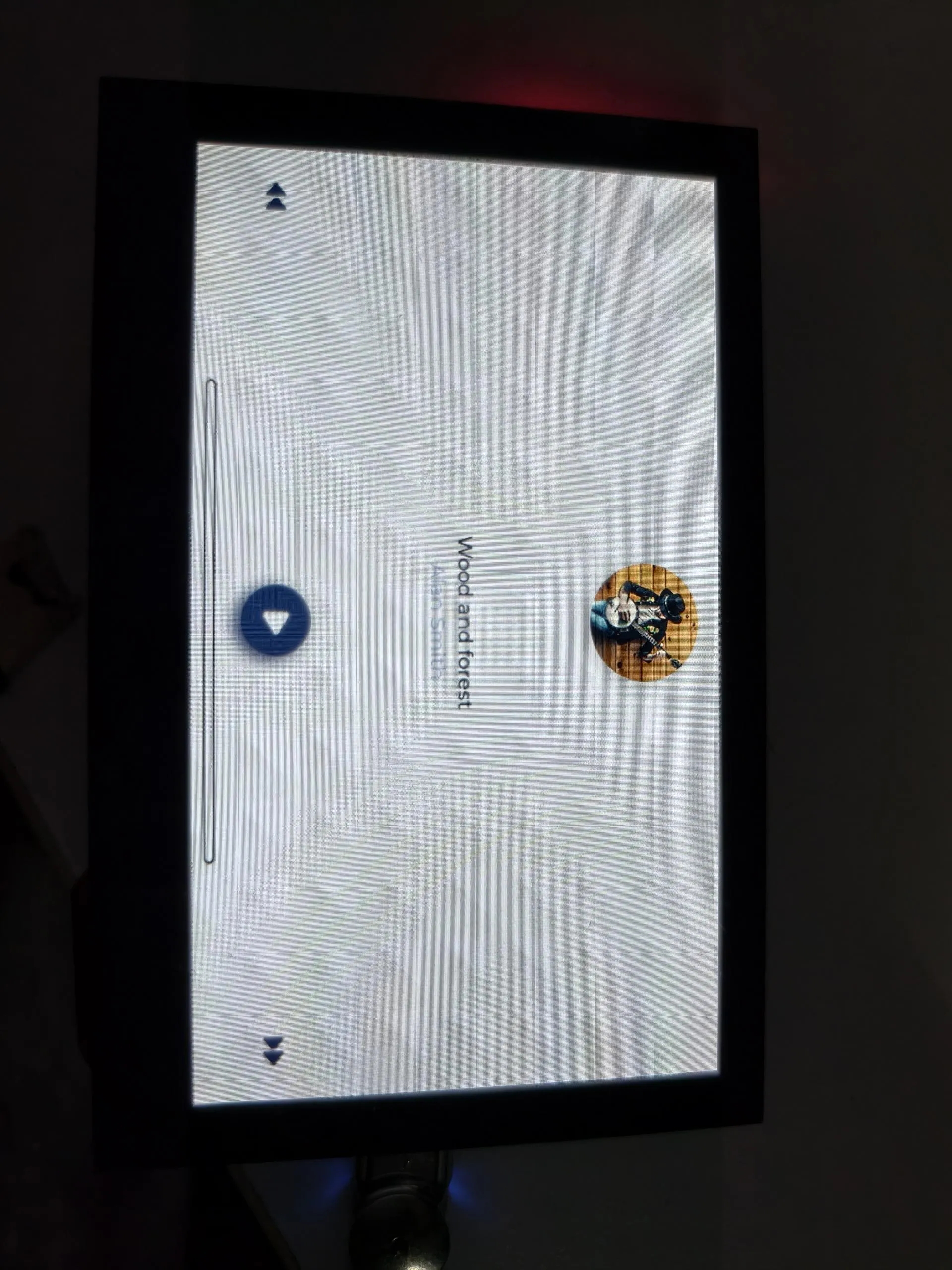
MusicPlayer
This example plays music from the TF card. The volume can be adjusted using the speaker button on the right.
Operation Result
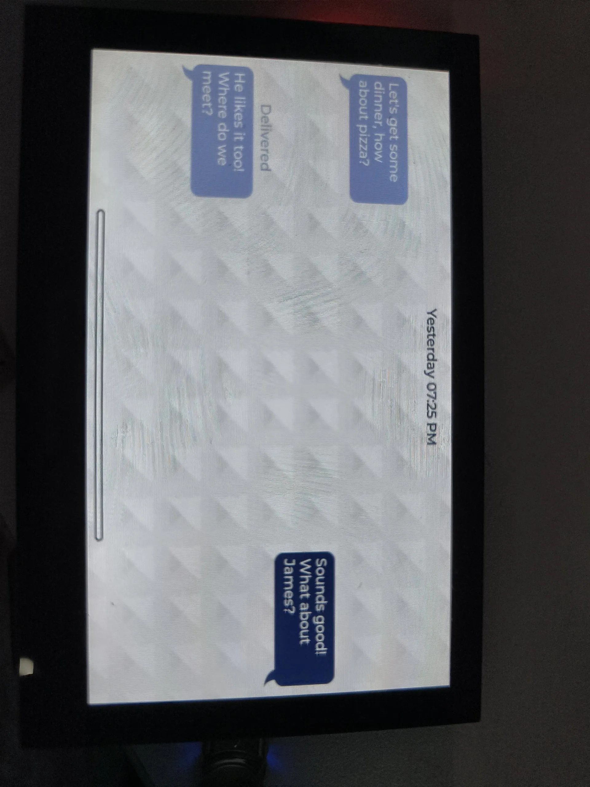
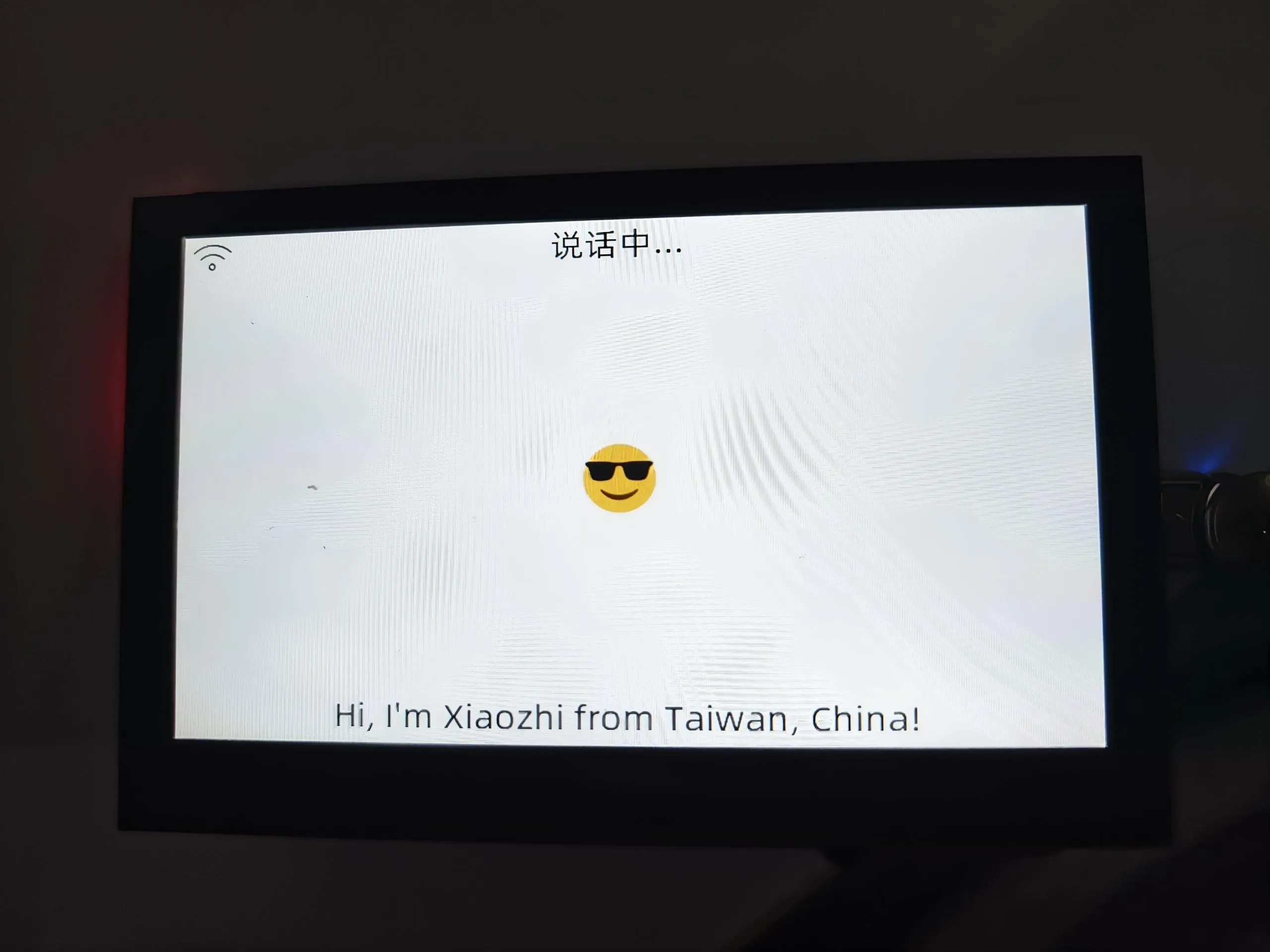
AIChats
This example runs XiaoZhi AI. After configuring XiaoZhi, you can say "Return to the application interface" to go back to the desktop.
Operation Result
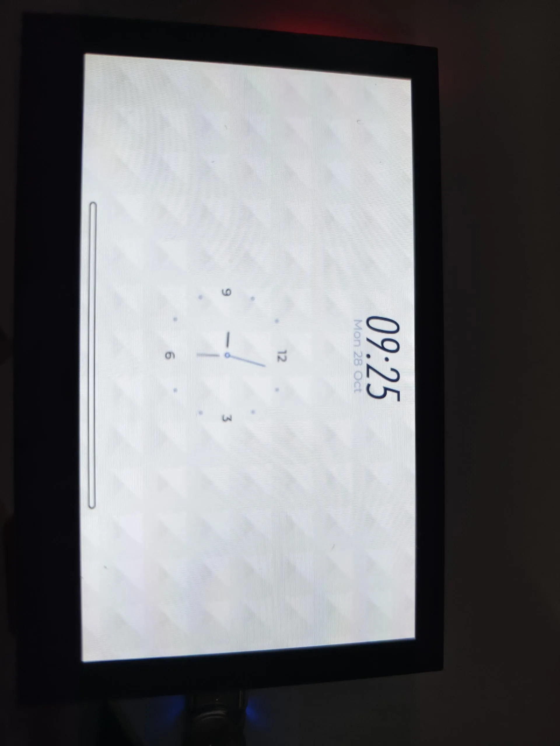
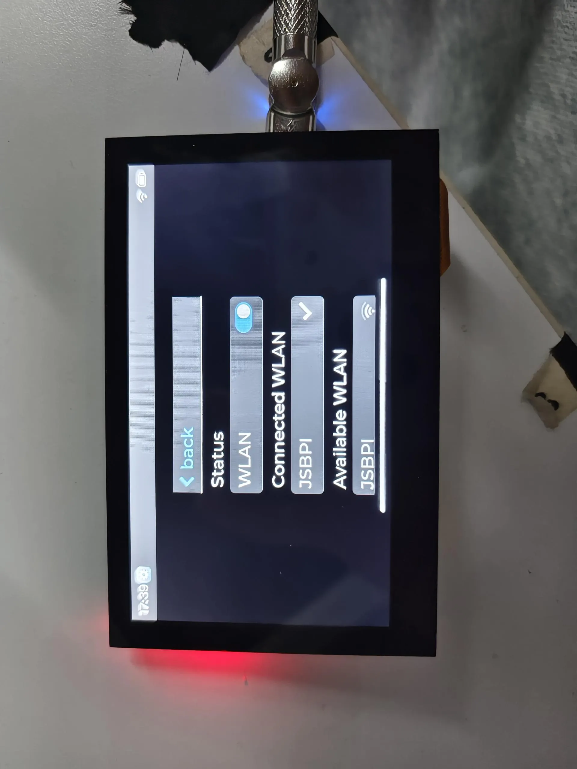
Settings
This example contains several widgets. Here is a brief introduction:
WLAN
This widget demonstrates Wi-Fi functionality. The specific operations are as follows:
- Click the switch to scan nearby Wi-Fi networks and display them in a list (Chinese Wi-Fi names cannot be displayed).
- Select the Wi-Fi you want to connect to, enter the password,and click the checkmark to connect (to exit the password input, first click the password box, then click a blank area).
- Wait for the connection to succeed. A checkmark ✅ appears for success, and a cross ❎ appears for failure.
- After a successful connection, Beijing time will be synchronized automatically.
Operation Result
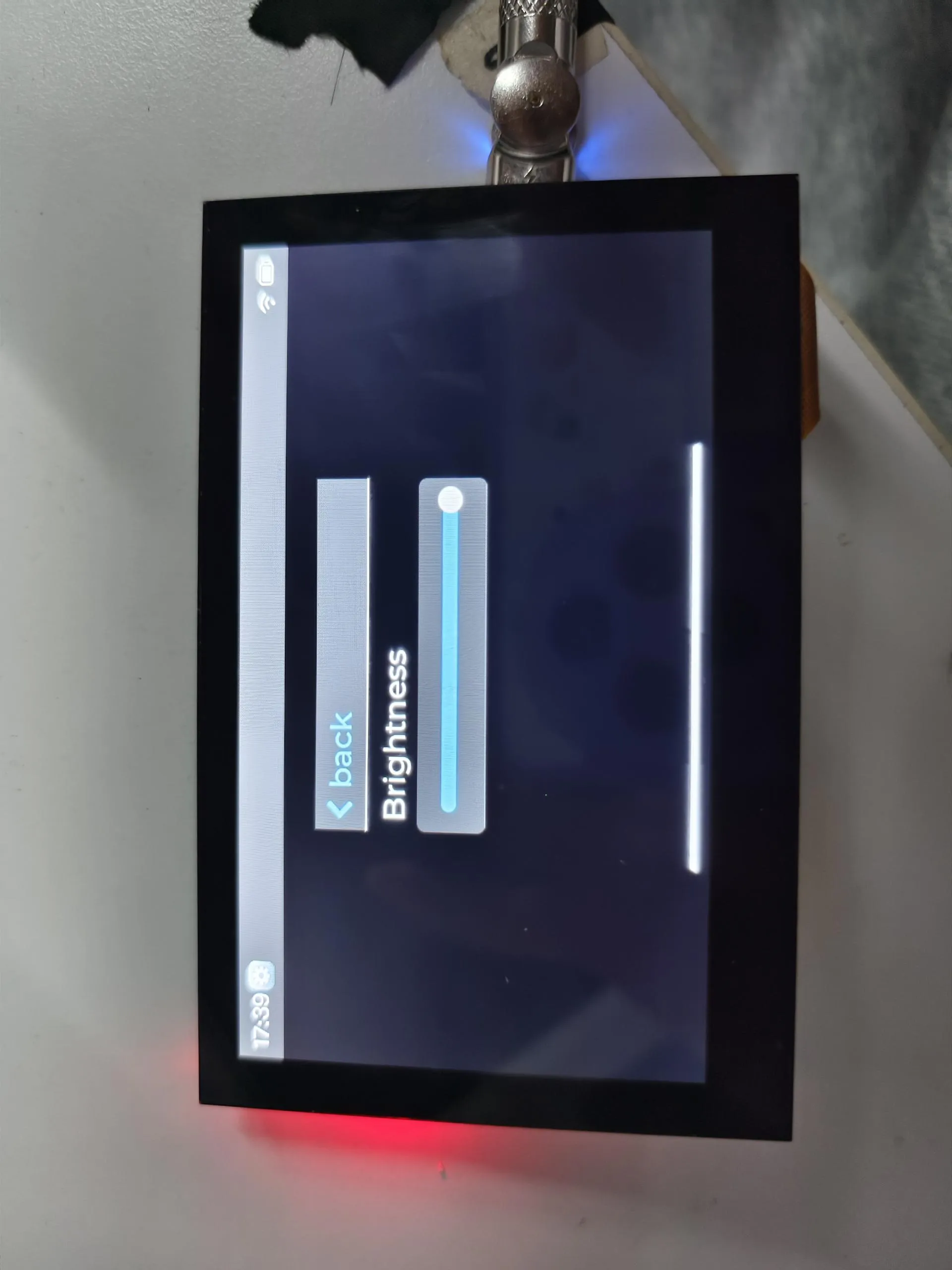
Sound & Display
These widgets demonstrate sound adjustment and brightness adjustment.
Operation Result
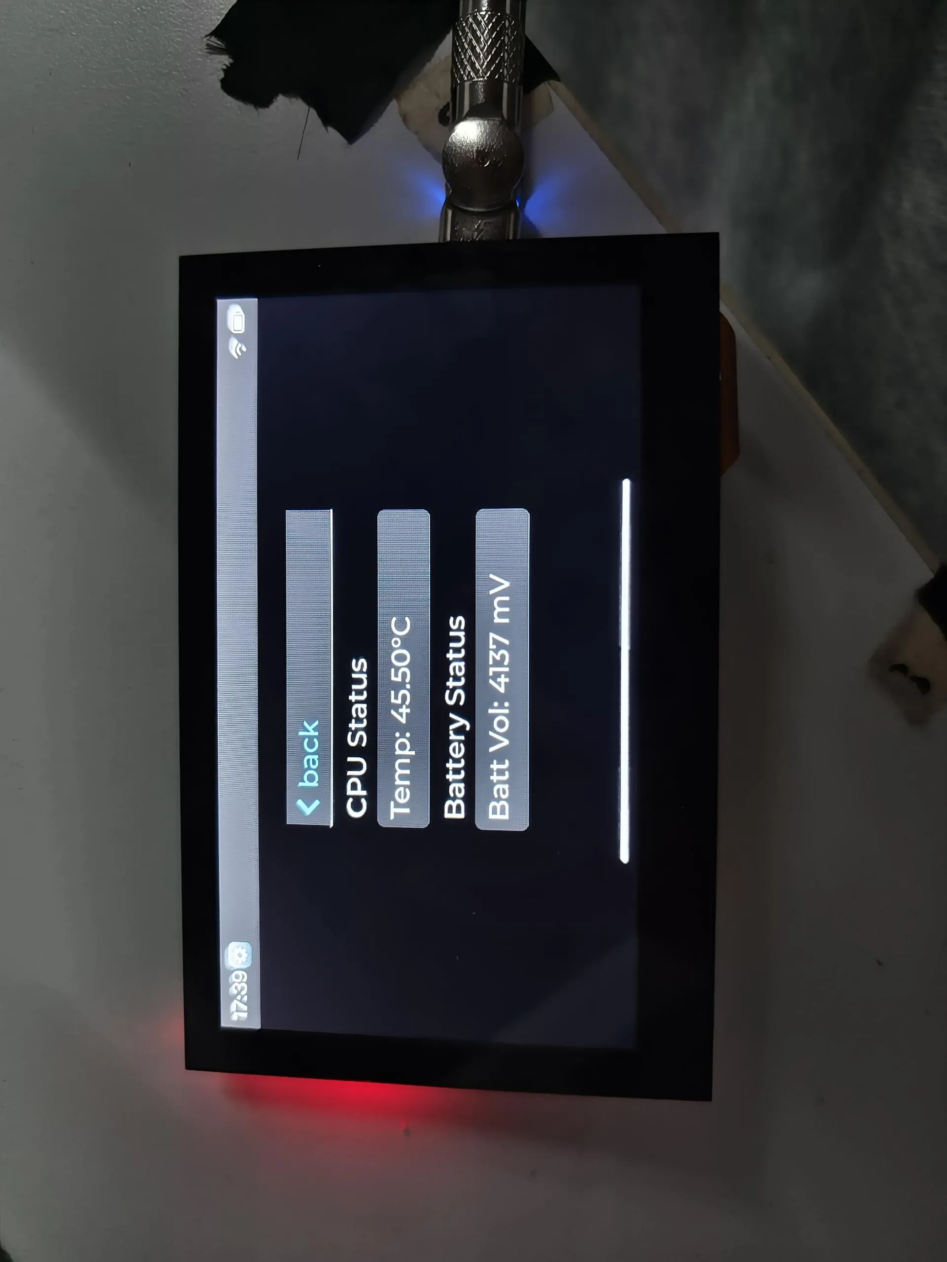
Battery
This widget displays the CPU temperature and current battery voltage.
Operation Result
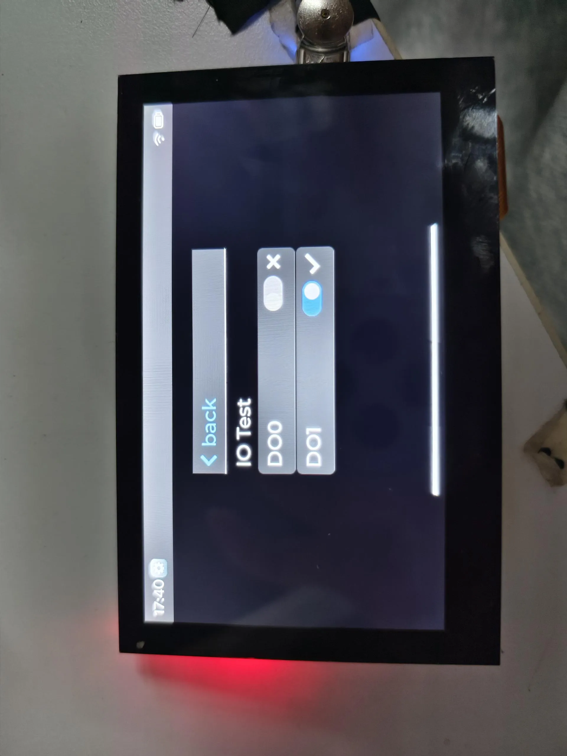
Isolationio
This widget demonstrates the isolation I/O test. You need to connect DI0 to DO0 and DI1 to DO1.
Operation Result
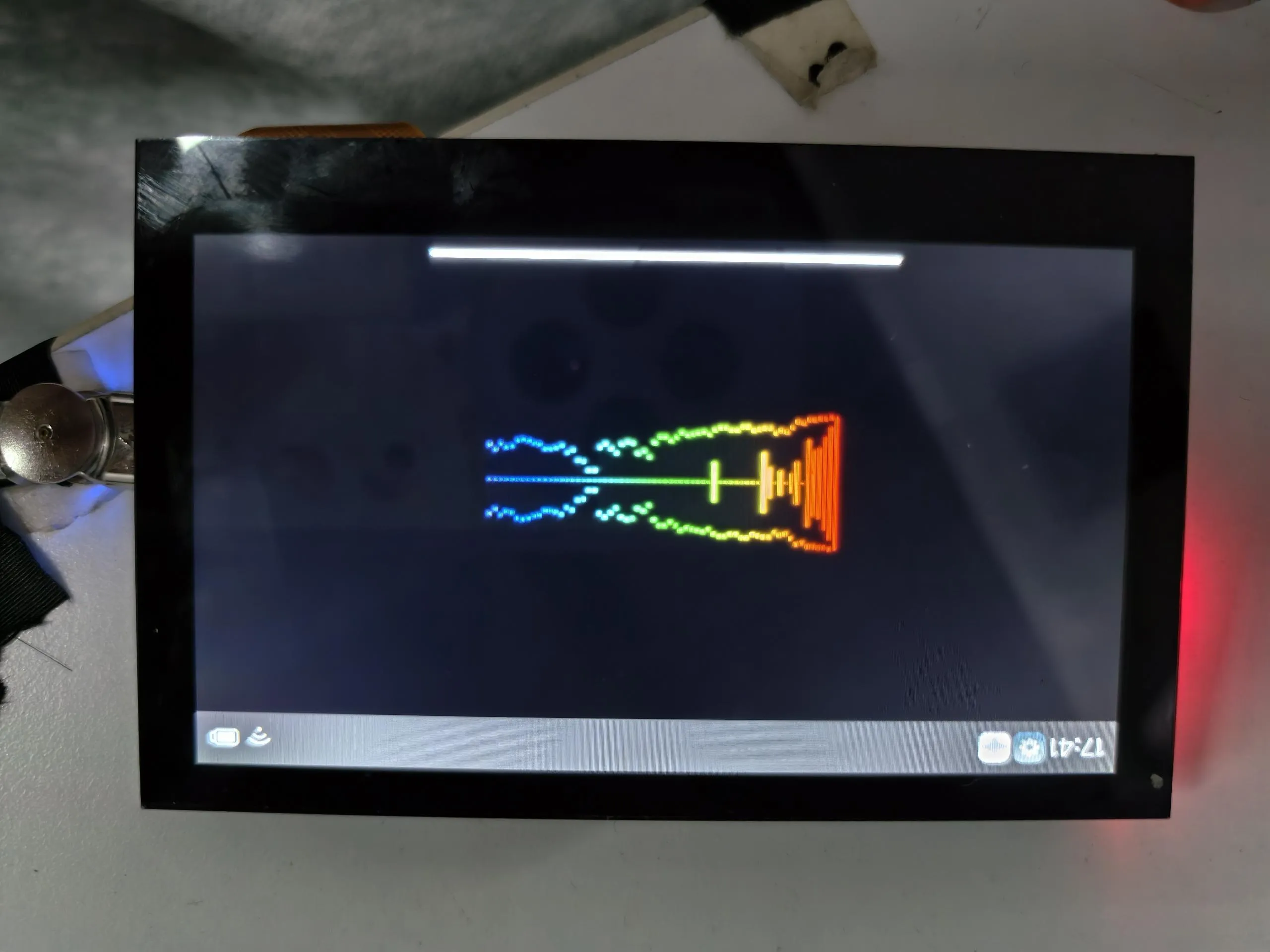
SpecAnalyzer
This example tests if the microphone is working properly by capturing sound and displaying it via animation.
Operation Result
Factory Reset
If you have flashed other programs and cannot test the factory firmware, you can restore the factory settings using the method below:
You need to know how to use Flash Tool. If not, you can click this link to learn.
Add
.\firmware\ESP32-S3-Touch-LCD-4.3C-Test.binto the Flash Tool. The flashing address is 0x00.Connect the development board to the computer. Check the COM port via Device Manager, then select the corresponding COM port in the Flash Tool and click Start. After the flashing is successful, press the RESET button.
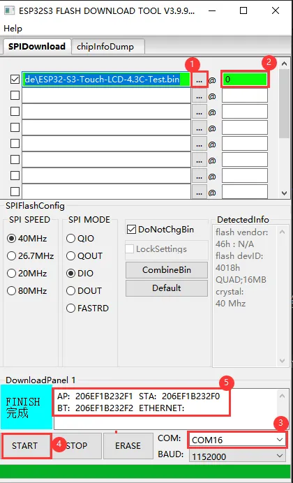
①. Add the firmware file.
②. Enter the flashing address.
③. Select the development board's COM port.
④. Start flashing.
⑤. Flashing completed.
Resources
1. Hardware Resources
Development Board Design File
2. Technical Manuals
Official ESP32-S3 Chip Manuals
- Datasheets: Chinese version | English version
- Technical Manuals: Chinese version | English version
Datasheets
3. Demo
- Demo (ESP-IDF and Arduino): ESP32-S3-Touch-LCD-4.3C_Demo.zip
Support
Monday-Friday (9:30-6:30) Saturday (9:30-5:30)
Email: services01@spotpear.com
[Tutorial Navigation]
- ESP32-S3-Touch-LCD-4.3C
- Working with Arduino
- Setting Up Development Environment
- 1. Installing and Configuring Arduino IDE
- 2. Installing Libraries
- 3. Arduino Project Parameter Settings
- Demo
- 01_i2c
- 02_rtc
- 03_lcd
- 04_isolation_io
- 05_sd
- 06_touch
- Hardware Connection
- Code
- Code Analysis
- Operation Result
- Hardware Connection
- Code
- Code Analysis
- Operation Result
- 08_wifi_scan
- 09_wifi_sta
- 10_wifi_ap
- 11_speaker_microphone
- Hardware Connection
- Code
- Code Analysis
- Operation Result
- Hardware Connection
- Code
- Code Analysis
- Operation Result
- Other Notes
- 13_lvgl_btn
- 14_lvgl_slider
- 15_udp_tcp_ntp
- Working with ESP-IDF
- Setting Up Development Environment
- Demo
- 01_i2c
- 02_rtc
- 03_lcd
- 04_isolation_io
- 05_sd
- 06_touch
- Hardware Connection
- Code
- Code Analysis
- Operation Result
- Hardware Connection
- Code
- Code Analysis
- Operation Result
- 08_wifi_scan
- 09_wifi_sta
- 10_wifi_ap
- 11_speaker_microphone
- Hardware Connection
- Code
- Code Analysis
- Operation Result
- Hardware Connection
- Code
- Code Analysis
- Operation Result
- 13_lvgl_codec
- 14_tcp_udp_ntp
- Using Factory Firmware
- Program Usage
- squareline
- DrawPanel
- Gallery
- MusicPlayer
- AIChats
- Settings
- SpecAnalyzer
- Factory Reset
- Resources
- Support