


- sales/support
Google Chat:---
- sales
+86-0755-88291180
- sales01
sales@spotpear.com
- sales02
dragon_manager@163.com
- support
tech-support@spotpear.com
- CEO-Complaints
zhoujie@spotpear.com
- Only Tech-Support
WhatsApp:13246739196
- Purchase/Shipping/Refund
WhatsApp:13424403025
- HOME
- >
- ARTICLES
- >
- Common Moudle
- >
- ESP
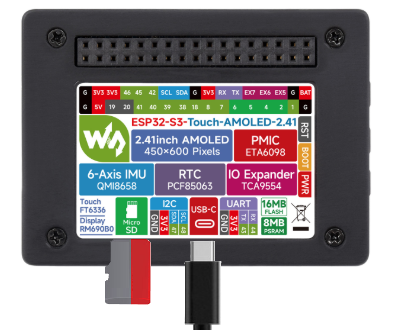
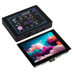
ESP32-S3-Touch-AMOLED-2.41 User Guide
Overview
Introduction
ESP32-S3-Touch-AMOLED-2.41 is a low-cost, high-performance and highly scalable ESP32_GUI development board designed by Waveshare. It supports 2.4GHz WiFi and BLE 5, integrated high-capacity Flash and PSRAM, onboard RTC, IMU and 2.41inch AMOLED screen, exposed UART, GPIO, I2C and USB bus interfaces, and a large number of demos and technical support for you to quickly develop automation and IoT products.
Features
- Equipped with high-performance Xtensa 32-bit LX7 dual-core processor, up to 240MHz main frequency
- Supports 2.4GHz Wi-Fi (802.11 b/g/n) and Bluetooth 5 (BLE), with onboard antenna
- Built-in 512KB SRAM and 384KB ROM, with onboard 16MB Flash and 8MB PSRAM
- Onboard 2.41inch wide capacitive touch screen with 600 × 450 resolution, 16.7M color
- AMOLED screen display uses a QSPI interface, touch screen uses an I2C interface, supporting 5-point touch and interrupt output
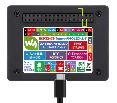
- Onboard RTC, IMU, TF card slot; leads out the I2C and UART buses, while exposing USB_N and USB_P; makes it suitable for various occasions
Onboard Resources
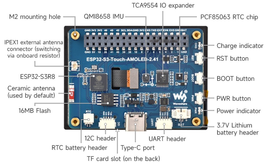
Interfaces
For more details, please refer to the Schematic diagram
| ESP32-Touch-AMOLED-2.41 | AMOLED | SD_Card | IMU | RTC | UART | I2C | KEY_IO | GPIO |
| GPIO0 | BOOT0 | |||||||
| GPIO1 | GPIO1 | |||||||
| GPIO2 | SD_CS | GPIO2 | ||||||
| GPIO3 | TP_RST | GPIO3 | ||||||
| GPIO4 | SD_SCLK | GPIO4 | ||||||
| GPIO5 | SD_MOSI | GPIO5 | ||||||
| GPIO6 | SD_MISO | GPIO6 | ||||||
| GPIO7 | GPIO7 | |||||||
| GPIO8 | GPIO8 | |||||||
| GPIO9 | QSPI_CS | |||||||
| GPIO10 | QSPI_CLK | |||||||
| GPIO11 | QSPI_D0 | |||||||
| GPIO12 | QSPI_D1 | |||||||
| GPIO13 | QSPI_D2 | |||||||
| GPIO14 | QSPI_D3 | |||||||
| GPIO15 | Key_BAT | |||||||
| GPIO16 | BAT_Control | |||||||
| GPIO17 | BAT_ADC | |||||||
| GPIO18 | GPIO18 | |||||||
| GPIO19 | USB_N | |||||||
| GPIO20 | USB_P | |||||||
| GPIO21 | AMOLED_RST | |||||||
| GPIO38 | GPIO38 | |||||||
| GPIO39 | GPIO39 | |||||||
| GPIO40 | GPIO40 | |||||||
| GPIO41 | GPIO41 | |||||||
| GPIO42 | GPIO42 | |||||||
| GPIO43 | UART_TXD | TXD | ||||||
| GPIO44 | UART_RXD | RXD | ||||||
| GPIO45 | GPIO45 | |||||||
| GPIO46 | GPIO46 | |||||||
| GPIO47 | TP_SDA | IMU_SDA | RTC_SDA | SDA | SDA | |||
| GPIO48 | TP_SCL | IMU_SCL | RTC_SCL | SCL | SCL | |||
| EN | RESET | |||||||
| EXIO0 | AMOLED_TE | |||||||
| EXIO1 | AMOLED_EN | |||||||
| EXIO2 | TP_INT | |||||||
| EXIO3 | IMU_INT2 | |||||||
| EXIO4 | IMU_INT1 | RTC_INT | ||||||
| EXIO5 | EXIO5 | |||||||
| EXIO6 | EXIO6 | |||||||
| EXIO7 | EXIO7 |
Dimensions
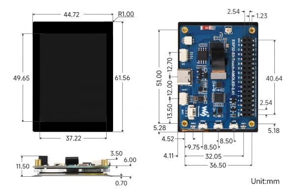
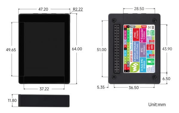
AMOLED Specifications

Usage Instructions
ESP32-S3-Touch-AMOLED-2.41 currently provides two development tools and frameworks, Arduino IDE and ESP-IDF, providing flexible development options, you can choose the right development tool according to your project needs and personal habits.
Development Tools
| Arduino IDEArduino IDE is an open source electronic prototyping platform, convenient and flexible, easy to get started. After a simple learning, you can start to develop quickly. At the same time, Arduino has a large global user community, providing an abundance of open source code, project examples and tutorials, as well as rich library resources, encapsulating complex functions, allowing developers to quickly implement various functions. |
| ESP-IDFESP-IDF, or full name Espressif IDE, is a professional development framework introduced by Espressif Technology for the ESP series chips. It is developed using the C language, including a compiler, debugger, and flashing tool, etc., and can be developed via the command lines or through an integrated development environment (such as Visual Studio Code with the Espressif IDF plugin). The plugin offers features such as code navigation, project management, and debugging, etc. |
Each of these two development approaches has its own advantages, and developers can choose according to their needs and skill levels. Arduino are suitable for beginners and non-professionals because they are easy to learn and quick to get started. ESP-IDF is a better choice for developers with a professional background or high performance requirements, as it provides more advanced development tools and greater control capabilities for the development of complex projects.
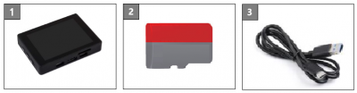
Components Preparation
- ESP32-S3-Touch-AMOLED-2.41 x1
- TF card x 1 (Optional)
- USB cable (Type A male to Type C male) x 1
Working with Arduino
This chapter introduces setting up the Arduino environment, including the Arduino IDE, management of ESP32 boards, installation of related libraries, program compilation and downloading, as well as testing demos. It aims to help users master the development board and facilitate secondary development.
Environment Setup
Download and Install Arduino IDE
- Click to visit the Arduino official website, select the corresponding system and system bit to download
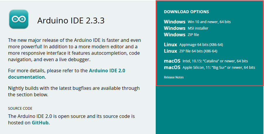
- Run the installer and install all by default
Install Arduino-ESP32
- Regarding ESP32-related motherboards used with the Arduino IDE, the esp32 by Espressif Systems library must be installed first.
- It is generally recommended to use Install Online. If online installation fails, use Install OIffline.
- To install the Arduino-ESP32 tutorial, please refer to Arduino board manager tutorial
- The ESP32-S3-Touch-AMOLED-2.41 development board comes with an offline package. Click here to download: esp32_package_3.0.7_arduino offline package
| Board name | Board installation requirement | Version number requirement |
|---|---|---|
| ESP32-S3-Touch-AMOLED-2.41 | "Install Offline" / "Install Online" | 3.0.7 |
Install Libraries
- When installing Arduino libraries, there are usually two ways to choose from: Install online and Install offline. If the library installation requires offline installation, you must use the provided library file
For most libraries, users can easily search and install them through the online library manager of the Arduino software. However, some open-source libraries or custom libraries are not synchronized to the Arduino Library Manager, so they cannot be acquired through online searches. In this case, users can only manually install these libraries offline. - For library installation tutorial, please refer to Arduino library manager tutorial
- ESP32-S3-Touch-AMOLED-2.41 library file is stored in the demo, click here to jump: ESP32-S3-Touch-AMOLED-2.41 Demo
| Library Name | Description | Version | Library Installation Requirement |
|---|---|---|---|
| LVGL | Graphical library | v8.4.0 | "Install Offline" |
Run the First Arduino Demo
New Project
- Run the Arduino IDE and select
File->New Sketch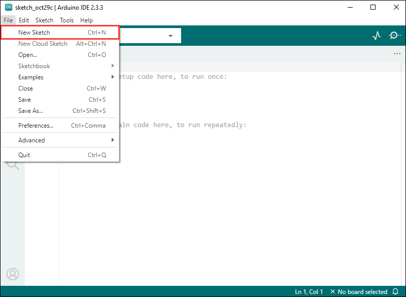
- Enter the code:
void setup() {
  // put your setup code here, to run once:
  Serial.begin(115200);
}

void loop() {
  // put your main code here, to run repeatedly:
  Serial.println("Hello, World!");
  delay(2000);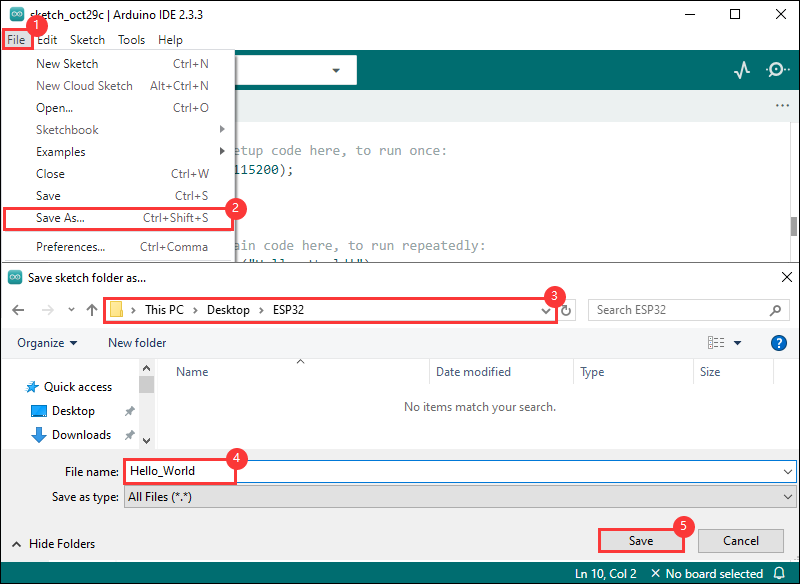
}- Save the project and select
File->Save As.... In the pop-up menu, select the path to save the project, and enter a project name, such as Hello_World, clickSave
Compile and Flash Demos
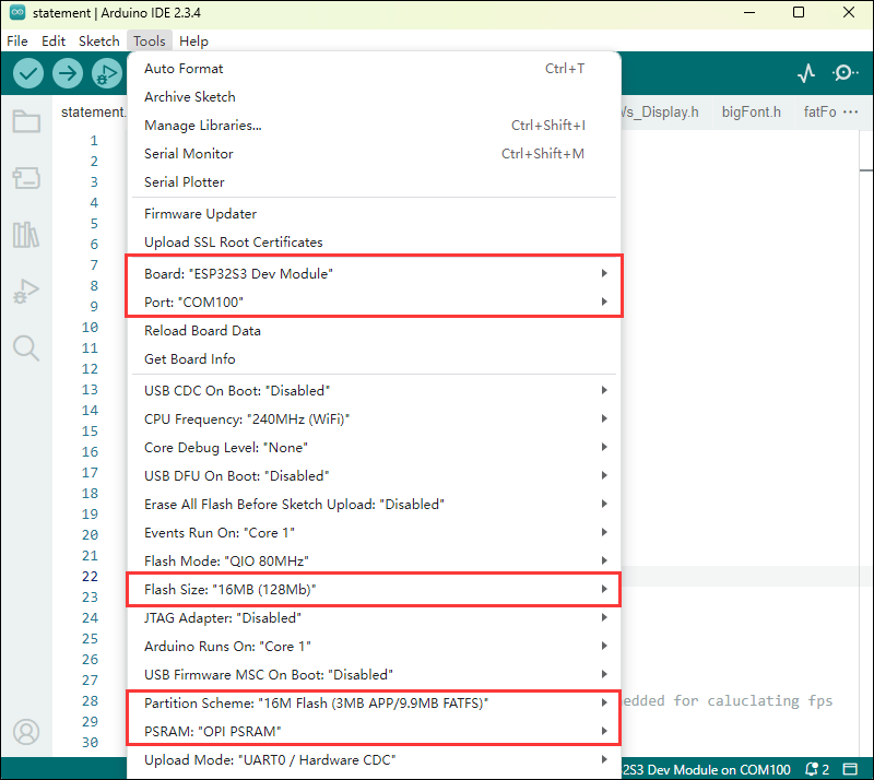
- Select the corresponding development board, take the ESP32S3 motherboard as an example:
①. Click to select the dropdown menu option Select Other Board and Port;
②. Search for the required development board model esp32s3 dev module and select;
③. Select COM Port;
④. Save the selection.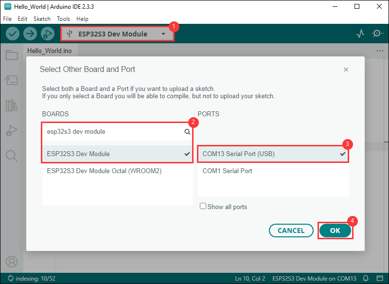
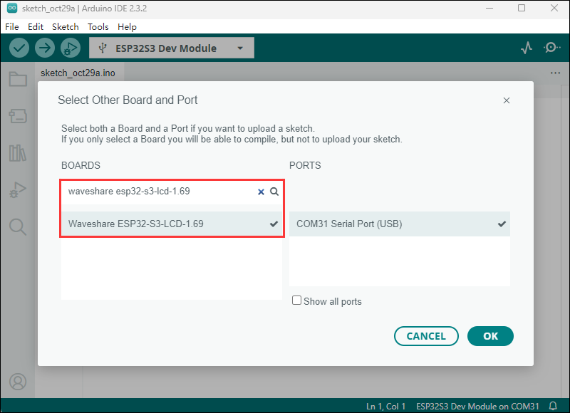
- Some development boards with specified version numbers support direct model selection, for example, "Waveshare ESP32-S3-LCD-1.69":
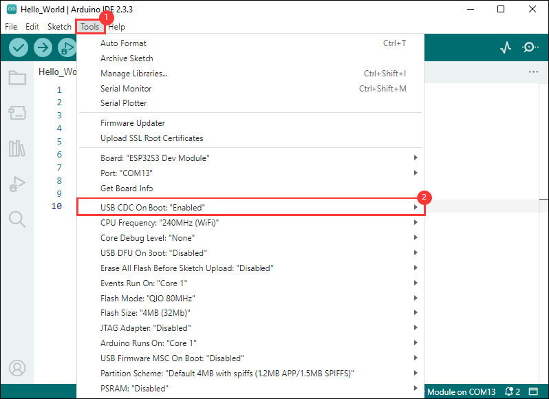
- If the ESP32S3 mainboard only has a USB port, you need to enable USB CDC, as shown in the following diagram:
- Compile and upload the program:
①. Compile the program; ②. Compile and download the program; ③. Download successful.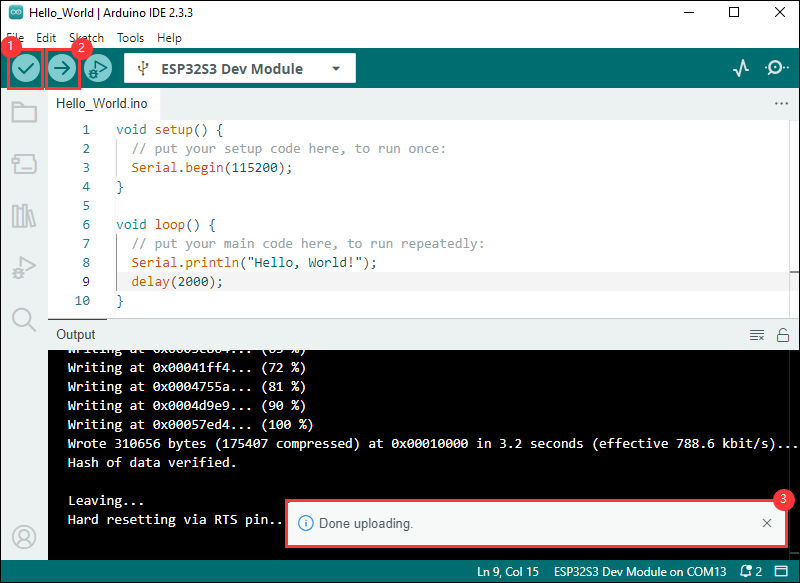
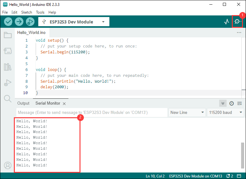
- Open the Serial Monitor window, and the demo will print "Hello World!" every 2 seconds, and the operation is as follows:
Demo

- Support direct selection of development board model: WaveShare ESP32-S3-Touch-AMOLED-2.41
| Demo | Basic Description | Dependency Library |
|---|---|---|
| 01_ADC_Test | Read the current voltage value of the system | - |
| 02_I2C_PCF85063 | Print the real-time time of RTC chip | - |
| 03_I2C_QMI8658 | Print the original data sent by the IMU | - |
| 04_SD_Card | Load and display the information of the TF card | - |
| 05_WIFI_STA | Set to STA mode to connect to WiFi and obtain an IP address | - |
| 06_WIFI_AP | Set to AP mode to obtain the IP address of the access device | - |
| 07_EX_GPIO | Using extended IO and internal IO | - |
| 08_Li_ION_Test | Enable lithium battery | - |
| 09_LVGL_Test | LVGL demo | LVGL |
| Arduino_Playablity | Playability demo | - |
01_ADC_Test
Demo description
- The analog voltage connected through the GPIO is converted to digital by the ADC, and then the actual system voltage is calculated and printed to the terminal
Hardware connection
- Connect the board to the computer using a USB cable
Code analysis
adc_bsp_init(void): Initializes ADC2, including creating an ADC one-time trigger unit and configuring channel 6 for ADC2.adc_get_value(float *value,int *data): Reads the value of ADC2 channel 6 and calculates the corresponding voltage value based on the reference voltage and resolution, stores it at the position where the incoming pointer points to, and stores 0 if the read fails.adc_example(void* parmeter): Initialize ADC2 and then create an ADC task that reads the ADC value every 1 second and calculates the system's voltage based on the raw ADC value
Result demonstration
| ADC_CHAN | GPIO_PIN |
|---|---|
| ADC2_CHANNEL_6 | GPIO17 |
- The program compilation download is complete, and opening the serial port monitor will show the printed ADC values and voltage, as shown in the following figure:
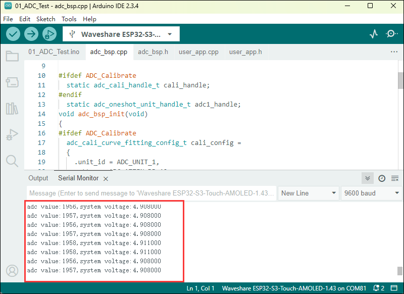
- The ADC sampling value is about 1900, and BAT voltage is about 4.9V. For a detailed analysis, you can refer to the schematic diagram
02_I2C_PCF85063
Demo description
- Through the I2C protocol, initialize the PCF85063 chip, set the time, and then periodically read the time and print it to the terminal
Hardware connection
- Connect the board to the computer using a USB cable
Code analysis
void PCF85063_example(void* parmeter): Create an RTC task to implement RTC functionality, read the clock from the RTC chip every 10 seconds and then print it to the terminal
Result demonstration
| RTC | GPIO_PIN |
|---|---|
| RTC_SDA | GPIO47 |
| RTC_SCL | GPIO48 |
| RTC_INT | EXIO4 |
- Open the serial port monitoring, you can see the RTC time of the printout, as shown in the figure below:
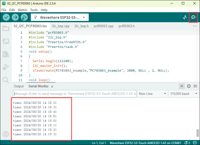
- Data is output every 10 seconds. If you need to modify or refer to it, you can directly access the PCF85063 source file for operations.
03_I2C_QMI8658
Demo description
- Through I2C protocol, initialize the QMI8658 chip, then read and print the corresponding attitude information every 1 second to the terminal
Hardware connection
- Connect the board to the computer using a USB cable
Code analysis
qmi8658c_example(void* parmeter): The function initializes the QMI8658 device, reading and printing accelerometer data, gyroscope data, and temperature data in an infinite loop, once every second. During the rotation of the board, the gyroscope data increases with greater rotation speed, and the accelerometer calculates the corresponding acceleration based on the current position.
Result demonstration
| IMU | GPIO_PIN |
|---|---|
| IMU_SDA | GPIO47 |
| IMU_SCL | GPIO48 |
| IMU_INT1 | EXIO4 |
| IMU_INT2 | EXIO3 |
- Open the serial port monitoring, and you can see the original data output from the IMU (Euler angles need to be converted by yourself), as shown in the following figure:
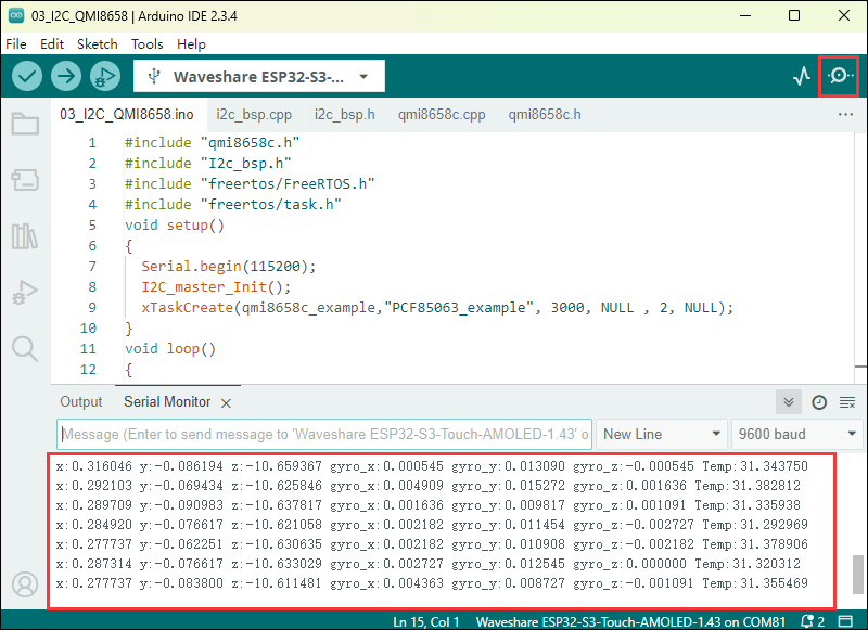
- Data is output once every second. If you need to modify or refer to it, you can directly access the qmi source file for operations.
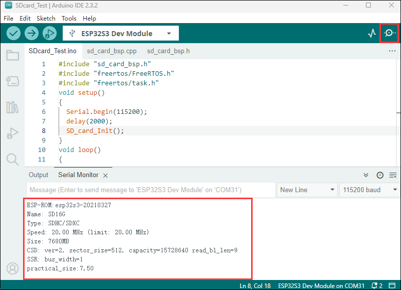
04_SD_Card
Demo description
- Select SPI or SDMMC direction to drive the TF card through macro definition, and print the TF card information to the terminal after successfully mounting the TF card
Hardware connection
- Install a TF card on the board (you must insert a TF card with a capacity of less than 64G first), and use a USB cable to connect the board to the computer
Code analysis
- The communication protocol of the TF card can be implemented according to the user's choice, find the macro definition
SD_Read_Modeunder the source filesd_card_bsp.cpp, the macro definition uses the SDMMC communication protocol by default, which can be modified to SDSPI
#define SD_Read_Mode USER_SPI
Result demonstration
| SPI/MMC | GPIO_PIN |
|---|---|
| CS | GPIO2 |
| MISO/D0 | GPIO6 |
| MOSI/CMD | GPIO5 |
| SCLK/MCLK | GPIO4 |
- Click on the serial port monitoring device, you can see the information of the output TF card, practical_size is the actual capacity of the TF card, as shown in the figure below:
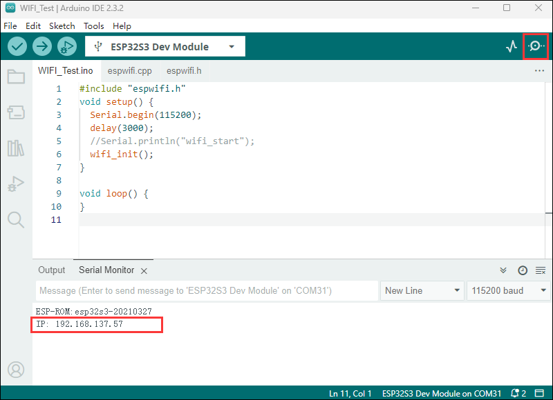
05_WIFI_STA
Demo description
- The development board is used as a terminal role, which can connect to the AP available in the environment, and print the obtained IP information to the terminal after successful connection
Hardware connection
- Connect the board to the computer using a USB cable
Code modification
The project realizes that the chip is connected to WIFI in STA mode and obtains the IP address, before compiling and downloading the firmware, some code needs to be modified, specifically changing the name and password of the WIFI router to those suitable for the environment.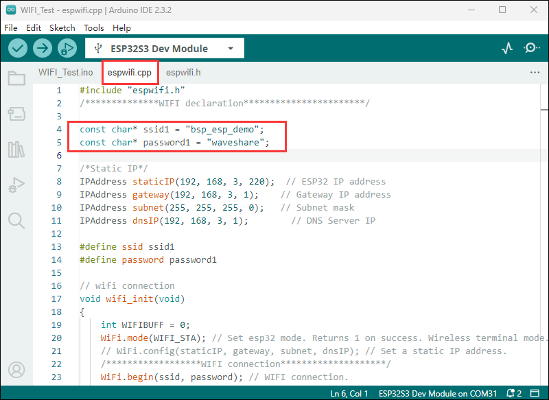
Code analysis
wifi_init(void): This function is used to initialize the Wi-Fi connection of the ESP32. It sets the ESP32 to Wi-Fi site mode and tries to connect to the specified Wi-Fi network (via thessidandpassword). If the connection is successful, it prints the local IP address; if the connection fails within a certain period (20 * 500 milliseconds), it prints the connection failure message. At the same time, the function can also set the auto-connection and auto-reconnect functions.
Result demonstration
- The chip is successfully connected to WIFI in STA mode, and you can see the obtained IP address by clicking on the serial port monitoring device.
06_WIFI_AP
Demo description
- Use the development board as an AP waiting for STA terminal connection
Hardware connection
- Connect the board to the computer using a USB cable
Code analysis
- The code initializes serial communication on the ESP32 and then creates a WiFi access point named "bsp_esp_demo" with the password "waveshare", and no other continuous operations are performed in a loop while the program runs.
const char* ssid     = "bsp_esp_demo";
const char* password = "waveshare";

WiFi.softAP(ssid,password);
Result demonstration
- Use your mobile phone or other device to connect to WIFI, the WiFi name is "bsp_esp_demo", and the password is "waveshare"
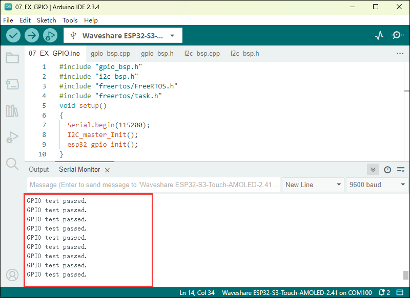
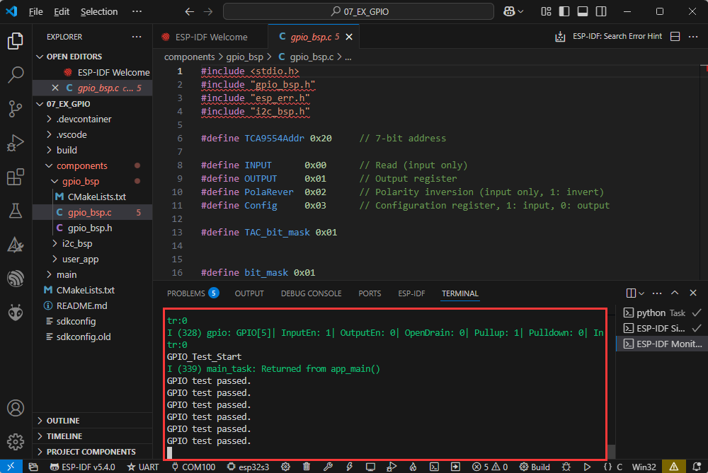
07_EX_GPIO
Demo description
- Test the basic functionality of extended IO and internal GPIO
Hardware connection
- Connect the board to the computer using a USB cable
- Use two cables to connect EXIO5 and EXIO6 together, and GPIO2 and GPIO1 together

Code analysis
I2C_master_Init(): Initialize I2C, which is the communication protocol for external IO extensionesp32_gpio_init(): Initialize GPIO, set GPIO1 and EXIO5 as output, and GPIO2 and EXIO6 as inputloop(): This is the logic for testing GPIO functionality, which can be modified by the user
Result demonstration
| GPIOx | GPIOy |
|---|---|
| GPIO1 | GPIO2 |
| EXIO5 | EXIO6 |
- The serial monitor outputs "GPIO test passed" to indicate successful testing, outputs "GPIO test failed" to indicate failure
08_Li_ION_Test
Demo description
- By controlling GPIO, supply power to the lithium battery
Hardware connection
- Connect the board to the computer using a USB cable
Code analysis
BAT_GPIO_Init(): Use GPIO16 to control the power supply of the lithium battery, responsible for initializing GPIO16BAT_ON(): Enable the lithium battery to power the systemBAT_OFF(): Disable the lithium battery supply to power the system
Result demonstration
- After enabling the lithium battery power supply in the software, connect the lithium battery and then use the PWR button to power the lithium battery
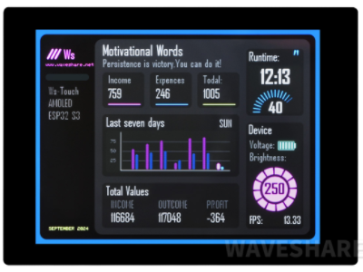
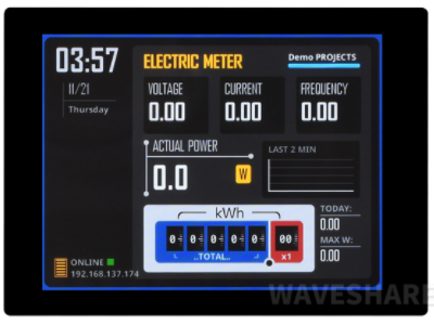
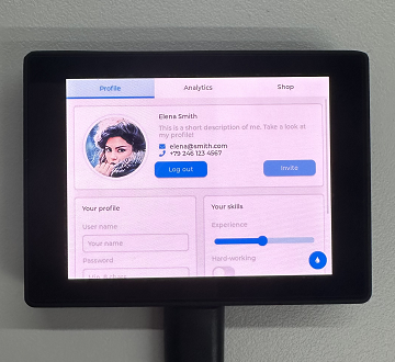
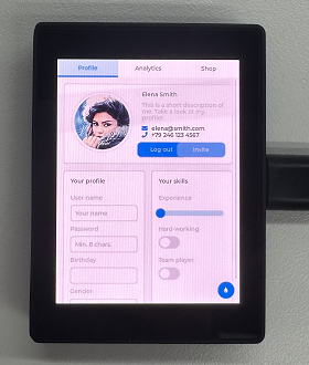
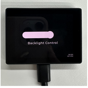
09_LVGL_Test
Demo description
- Implement some multifunctional GUI interfaces on the screen by porting LVGL
Hardware connection
- Connect the board to the computer using a USB cable
Code analysis
For LVGL, lvgl_conf.h is its configuration file, and below are explanations for some commonly used contents.
/*Color depth: 1 (1 byte per pixel), 8 (RGB332), 16 (RGB565), 32 (ARGB8888)*/
#define LV_COLOR_DEPTH 16//Color depth, a macro definition that must be concerned with porting LVGL


#define LV_MEM_CUSTOM 0
#if LV_MEM_CUSTOM == 0
    /*Size of the memory available for `lv_mem_alloc()` in bytes (>= 2kB)*/
    #define LV_MEM_SIZE (48U * 1024U)          /*[bytes]*/

    /*Set an address for the memory pool instead of allocating it as a normal array. Can be in external SRAM too.*/
    #define LV_MEM_ADR 0     /*0: unused*/
    /*Instead of an address give a memory allocator that will be called to get a memory pool for LVGL. E.g. my_malloc*/
    #if LV_MEM_ADR == 0
        #undef LV_MEM_POOL_INCLUDE
        #undef LV_MEM_POOL_ALLOC
    #endif

#else       /*LV_MEM_CUSTOM*/
    #define LV_MEM_CUSTOM_INCLUDE <stdlib.h>   /*Header for the dynamic memory function*/
    #define LV_MEM_CUSTOM_ALLOC   malloc
    #define LV_MEM_CUSTOM_FREE    free
    #define LV_MEM_CUSTOM_REALLOC realloc
#endif     /*LV_MEM_CUSTOM*/
//The above section is mainly for LVGL memory allocation,
//which defaults to lv_mem_alloc() versus lv_mem_free().
There are also some LVGL demos and file systems that can be set in the conf configuration file.
Code modification
- If you need to rotate the display by 90 degrees, you can find the macro definition
AMOLED_Rotatein the 09_LVGL_Test.ino file, choose of the two as below
#define AMOLED_Rotate  Rotate_90       //Landscape screen
#define AMOLED_Rotate  Rotate_NONO    //Portrait screen


Arduino_Playablity
- We also provide some playable demos for your reference, but it should be noted that the following demos are based on ESP32_Arduino versions below V3.0. Environment setup can be referred to below
- Process: ①: Install ESP32-2.0.x ②: Download demo ③: Porting library files ④:Compile and upload demo
- Click to view the tutorial on installing ESP32-2.0.x, please refer to Arduino board manager tutorial
- Click to jump to download the demo,ESP32-S3-AMOLED-2.41-Arduino_Playablity
- Click to view the tutorial on porting library files: Arduino library manager tutorial Offline porting library files
- Compile and upload the sample code
Demo description
- Implemented some playable GUI interfaces
Hardware connection
- Connect the board to the computer using a USB cable
Parameter settings
- The parameters of the demo need to be modified
Working with ESP-IDF
This chapter introduces setting up the ESP-IDF environment setup, including the installation of Visual Studio and the Espressif IDF plugin, program compilation, downloading, and testing of demos, to assist users in mastering the development board and facilitating secondary development. 
Environment Setup
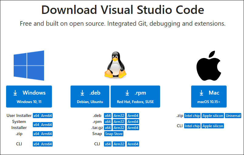
Download and Install Visual Studio
- Open the download page of VScode official website, choose the corresponding system and system bit to download
- After running the installation package, the rest can be installed by default, but here for the subsequent experience, it is recommended to check boxes 1, 2, and 3
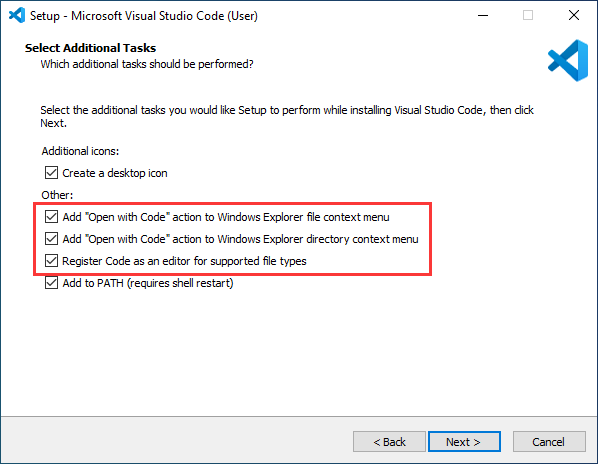
- After the first two items are enabled, you can open VSCode directly by right-clicking files or directories, which can improve the subsequent user experience.
- After the third item is enabled, you can select VSCode directly when you choose how to open it
Install Espressif IDF Plugin
- It is generally recommended to use Install Online. If online installation fails due to network factor, use Install OIffline.
- For more information about how to install the Espressif IDF plugin, see Install Espressif IDF Plugin
Run the First ESP-IDF Demo
New Project
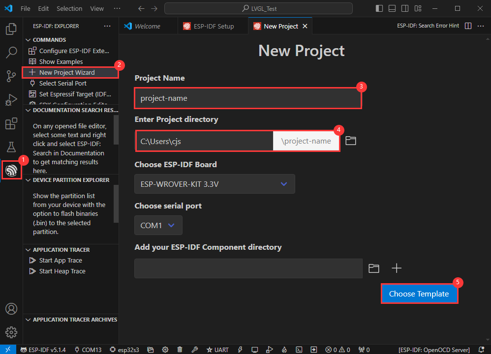
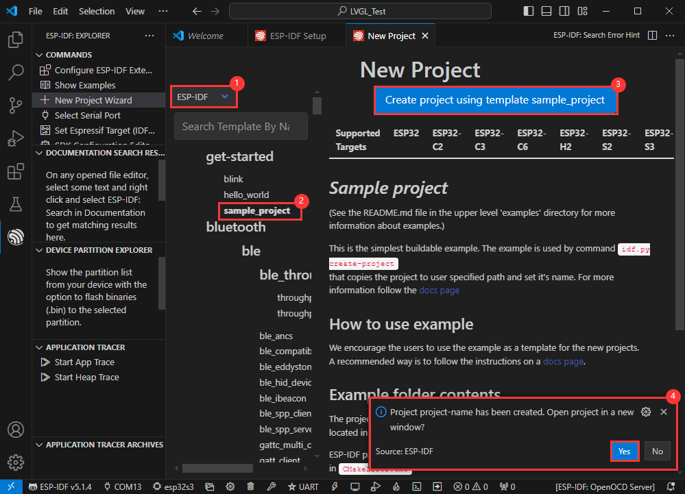
Create Demo
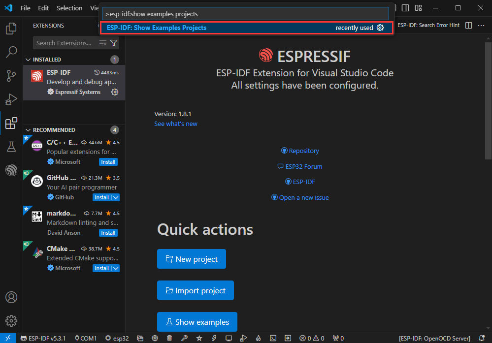
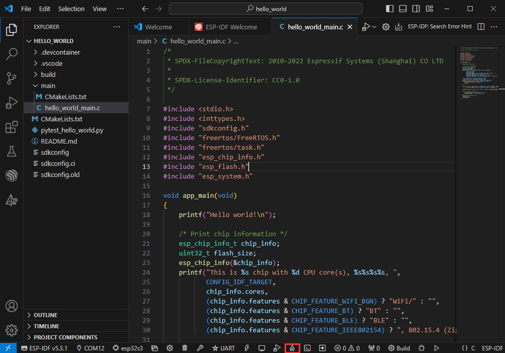
- Using the shortcut F1, enter esp-idf:show examples projects
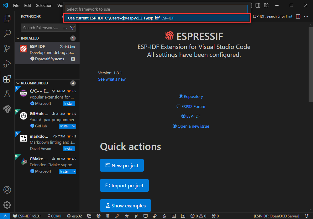
- Select your current IDF version
- Take the Hello world demo as an example
①Select the corresponding demo
②Its readme will state what chip the demo applies to (how to use the demo and the file structure are described below, omitted here)
③Click to create the demo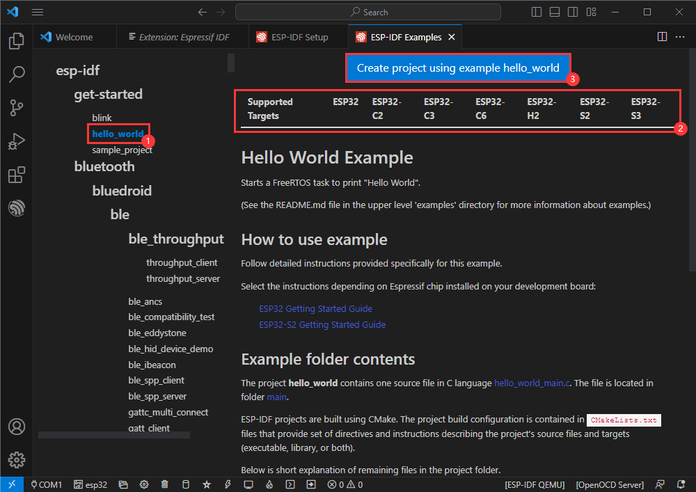
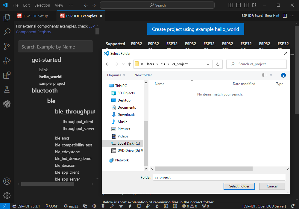
- Select the path to save the demo, and require that the demos cannot use folders with the same name
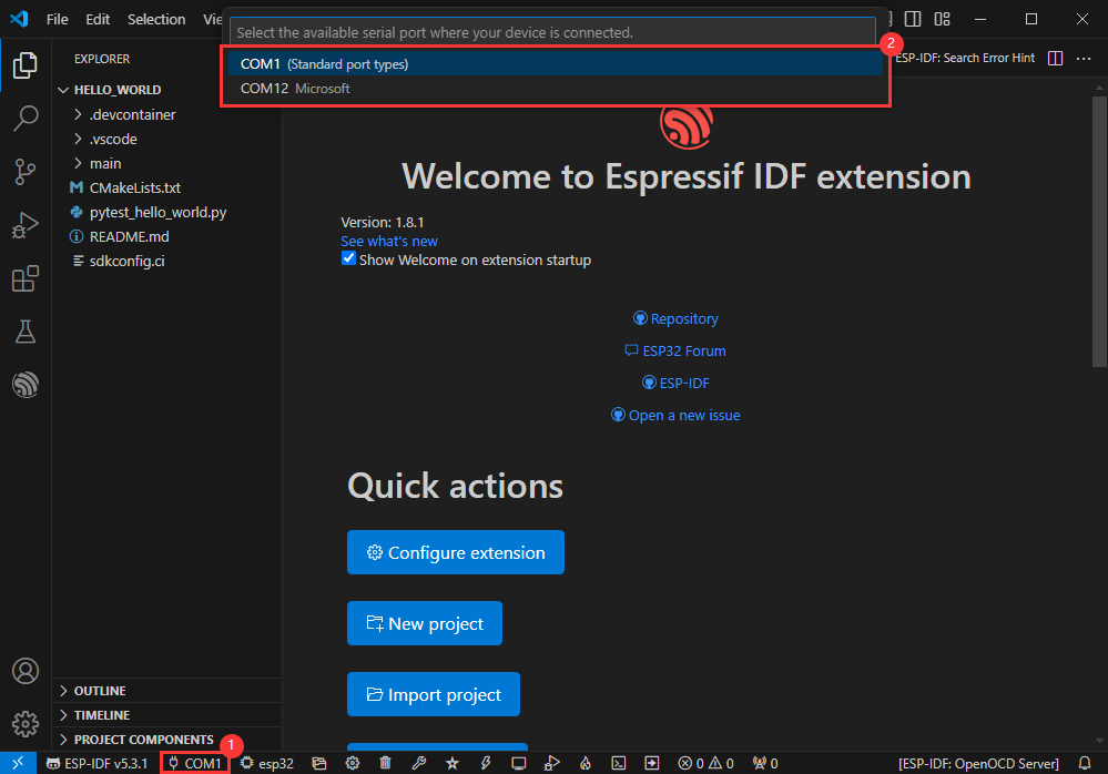
Modify COM Port
- The corresponding COM ports are shown here, click to modify them
- Please select the COM ports according to your device (You can view it from the device manager)
- In case of a download failure, please press the Reset button for more than 1 second or enter download mode, and wait for the PC to recognize the device again before downloading once more
Modify Driver Object
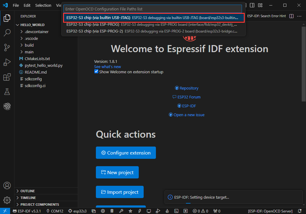
- Select the object we need to drive, which is our main chip ESP32S3
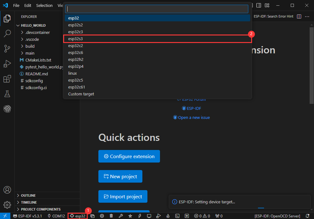
- Choose the path to openocd, it doesn't affect us here, so let's just choose one
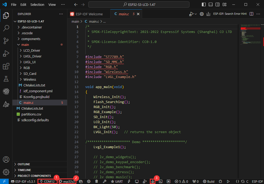
Other Status Bar Functions
①.ESP-IDF Development Environment Version Manager, when our project requires differentiation of development environment versions, it can be managed by installing different versions of ESP-IDF. When the project uses a specific version, it can be switched to by utilizing it
②.Device flashing COM port, select to flash the compiled program into the chip
③.Select set-target chip model, select the corresponding chip model, for example, ESP32-P4-NANO needs to choose esp32p4 as the target chip
④.menuconfig, click it to Modify sdkconfig configuration file Project configuration details
⑤.fullclean button, when the project compilation error or other operations pollute the compiled content, you can clean up all the compiled content by clicking it
⑥.Build project, when a project satisfies the build, click this button to compile
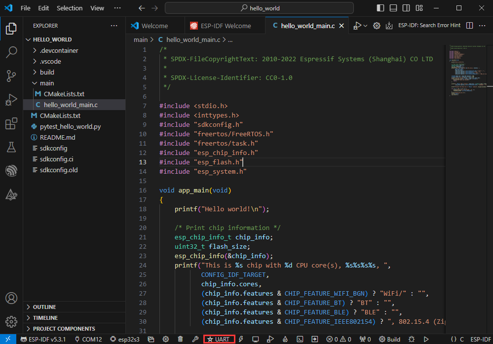
⑦.Current download mode, the default is UART
⑧.flash button, when a project build is completed, select the COM port of the corresponding development board, and click this button to flash the compiled firmware to the chip
⑨.monitor enable flashing port monitoring, when a project passes through Build --> Flash, click this button to view the log of output from flashing port and debugging port, so as to observe whether the application works normally
⑩.Debug
⑪.Build Flash Monitor one-click button, which is used to continuously execute Build --> Flash --> Monitor, often referred to as "little flame"
Compile, Flash and Serial Port Monitor
- Click on the all-in-one button we described before to compile, flash and open the serial port monitor
- It may take a long time to compile especially for the first time
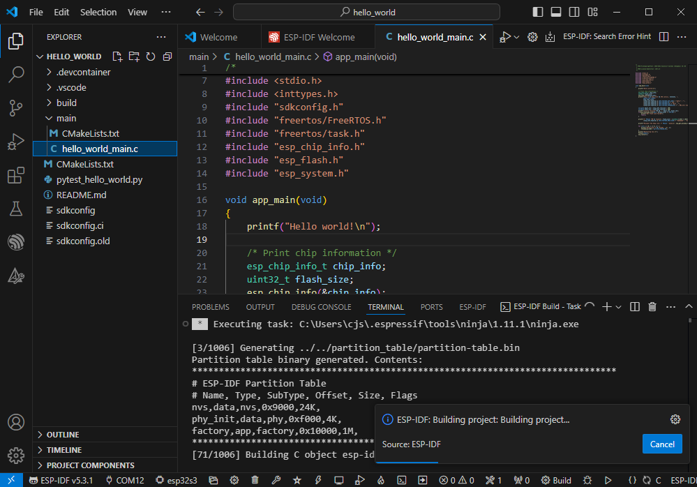
- During this process, the ESP-IDF may take up a lot of CPU resources, so it may cause the system to lag
- If it is the first time to flash the program for a new project, you will need to select the download method, and select UART
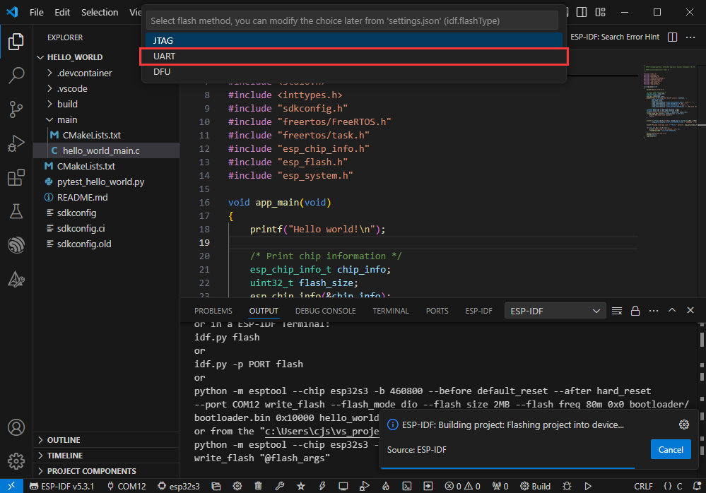
- This can also be changed later in the Download methods section (click on it to pop up the options)
- As it comes with the onboard automatic download circuit, it can be downloaded automatically without manual operation
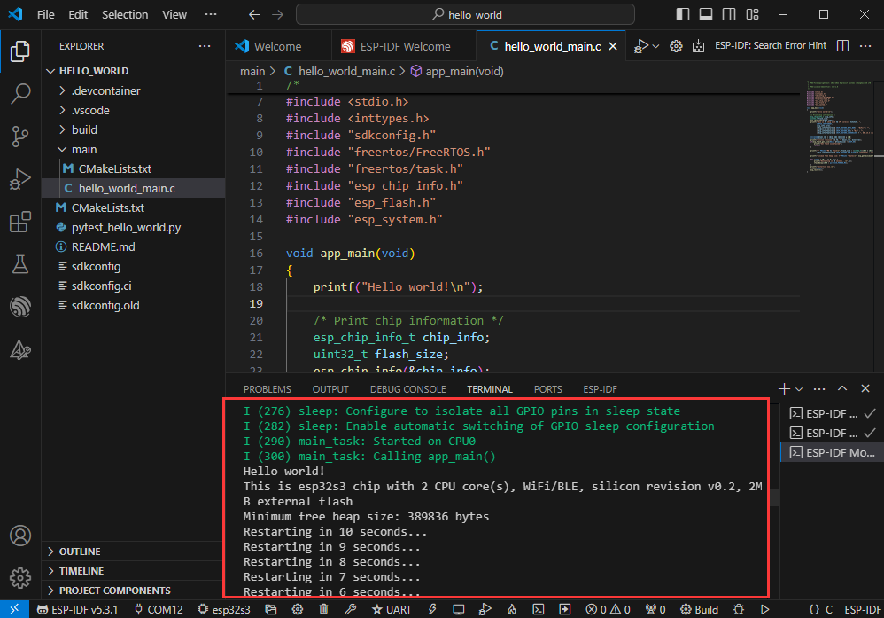
- After successful download, it will automatically enter the serial monitor, you can see the chip output the corresponding information and be prompted to restart after 10S
Use the IDF Demos
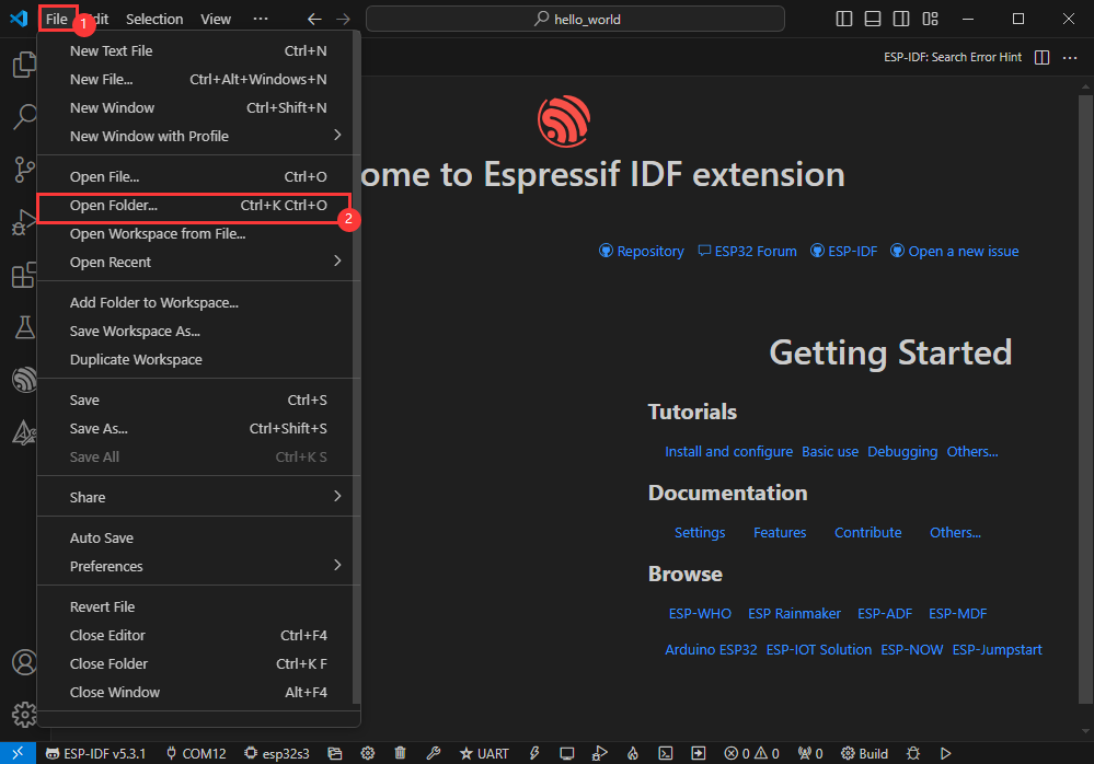
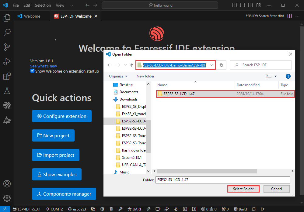
Open In the Software
- Open VScode software and select the folder to open the demo
- Select the provided ESP-IDF example and click to select the file (located in the /Demo/ESP-IDF path under demo)
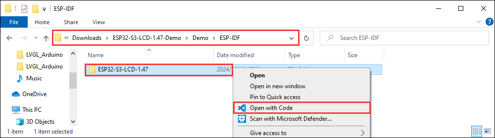
Open from Outside the Software
- Select the project directory correctly and open the project, otherwise it will affect the compilation and flashing of subsequent programs
- After connecting the device, select the COM port and model, click below to compile and flash to achieve program control
ESP-IDF Project Details
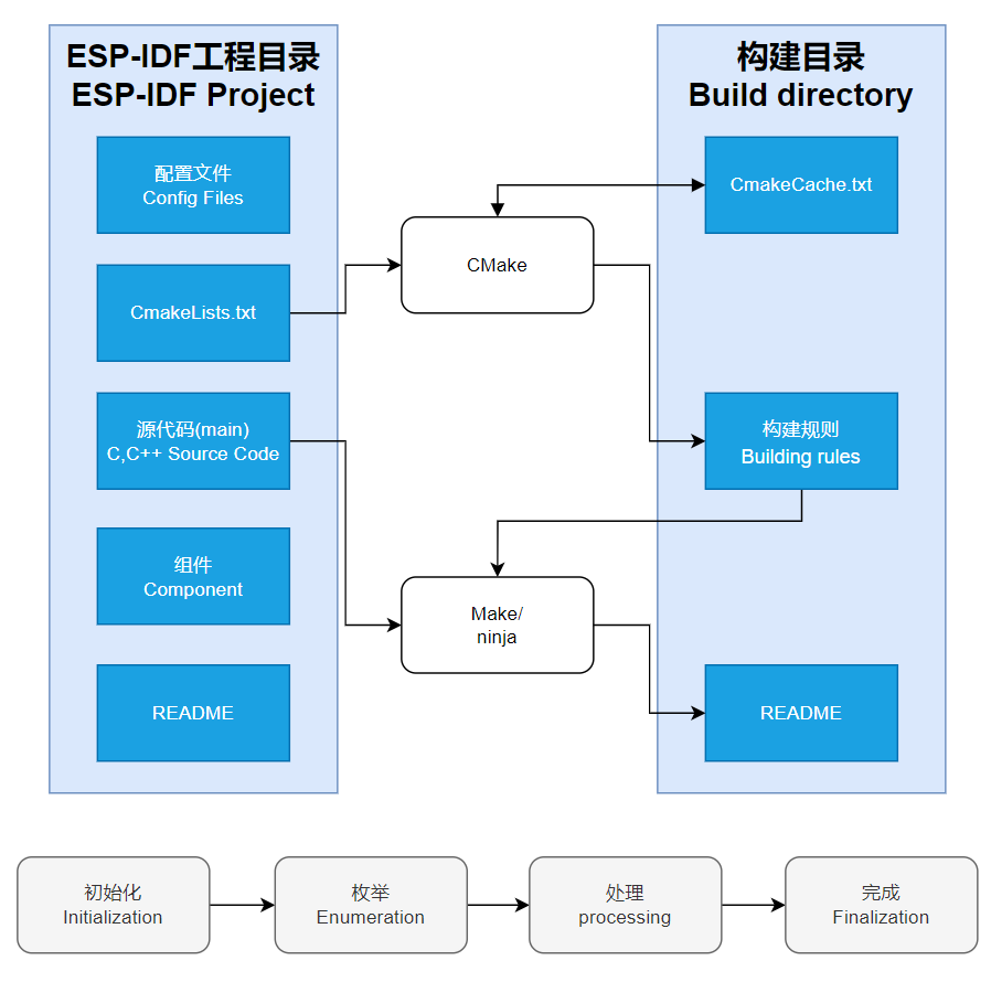
- Component: The components in ESP-IDF are the basic modules for building applications, each component is usually a relatively independent code base or library, which can implement specific functions or services, and can be reused by applications or other components, similar to the definition of libraries in Python development.
- Component reference: The import of libraries in the Python development environment only requires to "import library name or path", while ESP-IDF is based on the C language, and the importing of libraries is configured and defined through
CMakeLists.txt. - The purpose of CmakeLists.txt: When compiling ESP-IDF, the build tool
CMakefirst reads the content of the top-levelCMakeLists.txtin the project directory to read the build rules and identify the content to be compiled. When the required components and demos are imported into theCMakeLists.txt, the compilation toolCMakewill import each content that needs to be compiled according to the index. The compilation process is as follows:
- Component reference: The import of libraries in the Python development environment only requires to "import library name or path", while ESP-IDF is based on the C language, and the importing of libraries is configured and defined through
Demo

| Demo | Basic Description | Dependency Library |
|---|---|---|
| 01_ADC_Test | Read the current voltage value of the system | - |
| 02_I2C_PCF85063 | Print the real-time time of RTC chip | - |
| 03_I2C_QMI8658 | Print the original data sent by the IMU | - |
| 04_SD_Card | Enable lithium battery | - |
| 05_WIFI_STA | Load and display the information of the TF card | - |
| 06_WIFI_AP | Set to STA mode to connect to WiFi and obtain an IP address | - |
| 07_EX_GPIO | Set to AP mode to obtain the IP address of the access device | - |
| 08_Li_ION_Test | Using extended IO and internal IO | - |
| 09_LVGL_Test | LVGL demo | LVGL |
| 10_FactoryProgram | Comprehensive demo | LVGL |
01_ADC_Test
Demo description
- The analog voltage connected through the GPIO is converted to digital by the ADC, and then the actual system voltage is calculated and printed to the terminal
Hardware connection
- Connect the board to the computer using a USB cable

Code analysis
adc_bsp_init(void): Initializes ADC2, including creating an ADC one-time trigger unit and configuring channel 6 for ADC2.adc_get_value(float *value,int *data): Reads the value of ADC2 channel 6 and calculates the corresponding voltage value based on the reference voltage and resolution, stores it at the position where the incoming pointer points to, and stores 0 if the read fails.adc_example(void* parmeter): Initialize ADC2 and then create an ADC task that reads the ADC value every 1 second and calculates the system's voltage based on the raw ADC value
Result demonstration
| ADC_CHAN | GPIO_PIN |
|---|---|
| ADC2_CHANNEL_6 | GPIO17 |
- After the program is flashed, open the monitoring device and you can see the output ADC values and voltage, as shown in the figure below:
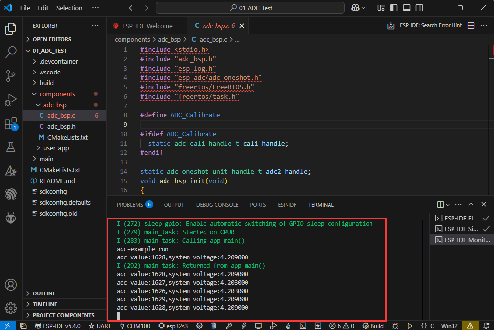
- The ADC sampling value is about 1628, and BAT voltage is about 4.2V. For a detailed analysis, you can refer to the schematic diagram
02_I2C_PCF85063
Demo description
- Through the I2C protocol, initialize the PCF85063 chip, set the time, and then periodically read the time and print it to the terminal
Hardware connection
- Connect the board to the computer using a USB cable
Code analysis
void PCF85063_example(void* parmeter): Create an RTC task to implement RTC functionality, read the clock from the RTC chip every 10 seconds and then output it to the terminal
Result demonstration
| RTC | GPIO_PIN |
|---|---|
| RTC_SDA | GPIO47 |
| RTC_SCL | GPIO48 |
| RTC_INT | EXIO4 |
- After flashing is completed, open the monitoring device to see the printed RTC time, as shown in the following figure:
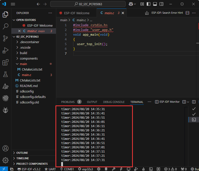
- Data is output every 10 seconds. If you need to modify or refer to it, you can directly access the PCF85063 source file for operations.
03_I2C_QMI8658
Demo description
- Through I2C protocol, initialize the QMI8658 chip, then read and print the corresponding attitude information every 1 second to the terminal
Hardware connection
- Connect the board to the computer using a USB cable
Code analysis
qmi8658c_example(void* parmeter): The function initializes the QMI8658 device, reading and printing accelerometer data, gyroscope data, and temperature data in an infinite loop, once every second.
Result demonstration
| IMU | GPIO_PIN |
|---|---|
| IMU_SDA | GPIO47 |
| IMU_SCL | GPIO48 |
| IMU_INT1 | EXIO4 |
| IMU_INT2 | EXIO3 |
After the demo is flashed, the running result of the device is as follows:
- Open the serial port monitoring, and you can see the original data output from the IMU (Euler angles need to be converted by yourself), as shown in the following figure:
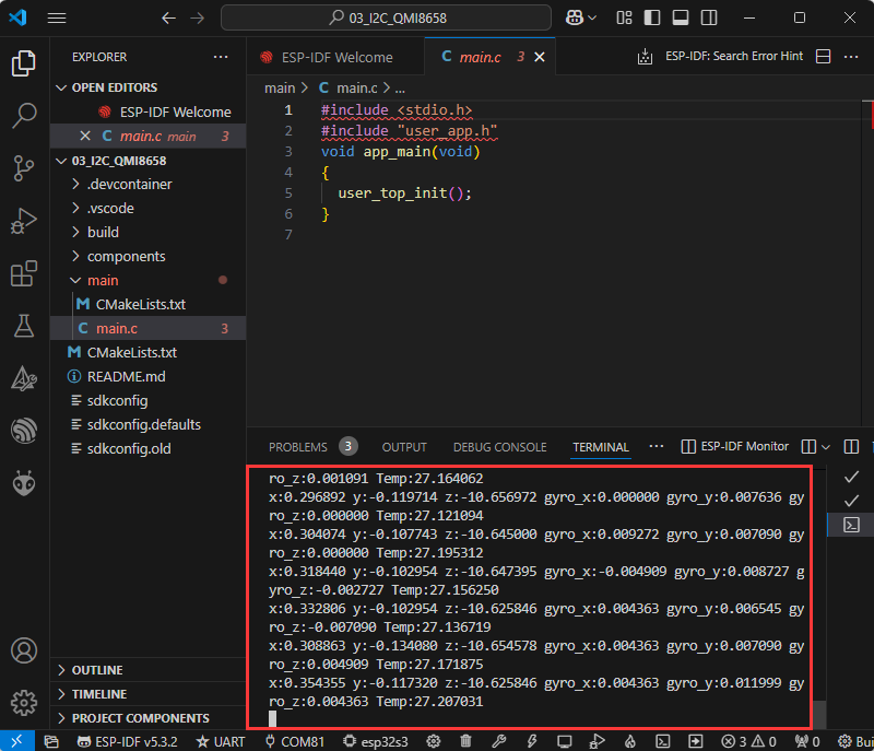
- You can see that it is output every 1 second. If you need to modify or refer to it, you can directly go to the qmi source file to modify it
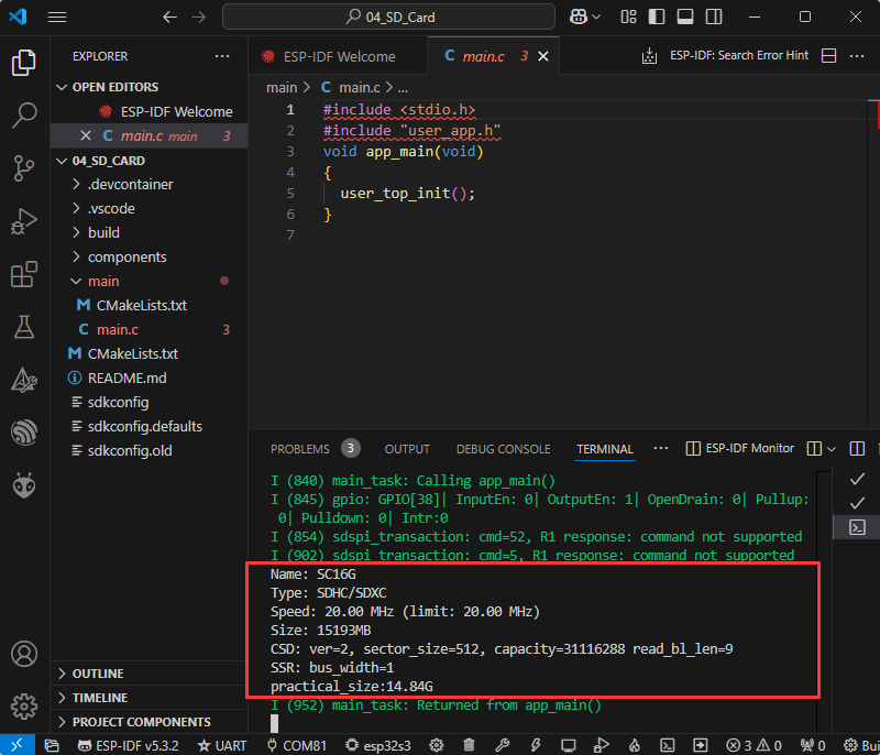
04_SD_Card
Demo description
- Select SPI or SDMMC direction to drive the TF card through macro definition, and print the TF card information to the terminal after successfully mounting the TF card
Hardware connection
- Install a TF card on the board (you must insert a TF card with a capacity of less than 64G first), and use a USB cable to connect the board to the computer

Code analysis
- The communication protocol of the TF card can be implemented according to the user's choice, find the macro definition
SD_Read_Modeunder the source filesd_card_bsp.c, the macro definition uses the SDMMC communication protocol by default, which can be modified to SDSPI
#define SD_Read_Mode USER_SPIResult demonstration
| SPI/MMC | GPIO_PIN |
|---|---|
| CS | GPIO2 |
| MISO/D0 | GPIO6 |
| MOSI/CMD | GPIO5 |
| SCLK/MCLK | GPIO4 |
- Click on the serial port monitoring device, you can see the information of the output TF card, practical_size is the actual capacity of the TF card, as shown in the figure below:
05_WIFI_STA
Demo description
- The development board is used as a terminal role, which can connect to the AP available in the environment, and print the obtained IP information to the terminal after successful connection
Hardware connection
- Connect the board to the computer using a USB cable
Code analysis
espwifi_Init(void): This function is used for WiFi initialization on ESP32. It sequentially initializes non-volatile storage, the TCP/IP stack, creates a default event loop and a default WiFi site network interface, initializes WiFi with the default configuration, registers event handlers to handle WiFi and IP-related events, sets WiFi connection parameters, and starts WiFi.
Code modification
The project realizes that the chip is connected to WIFI in STA mode and obtains the IP address, before compiling and downloading the firmware, some code needs to be modified, specifically changing the name and password of the WIFI router to those suitable for the environment.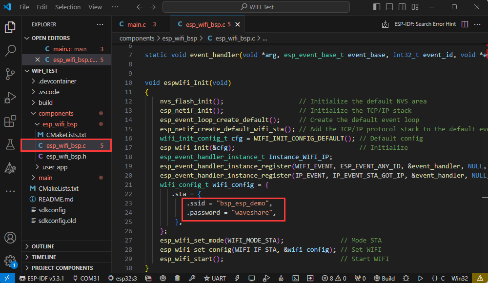
Result demonstration
After the demo is flashed, the running result of the device is as follows:
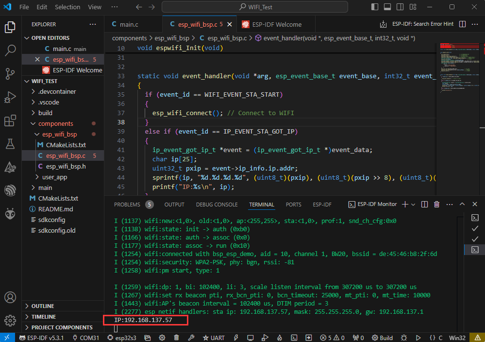
- The chip successfully connects to WIFI and obtains an IP address while in STA mode.
06_WIFI_AP
Demo description
- Use the development board as an AP waiting for STA terminal connection, and print the assigned IP to the terminal after a successful connection
Hardware connection
- Connect the board to the computer using a USB cable
Code analysis
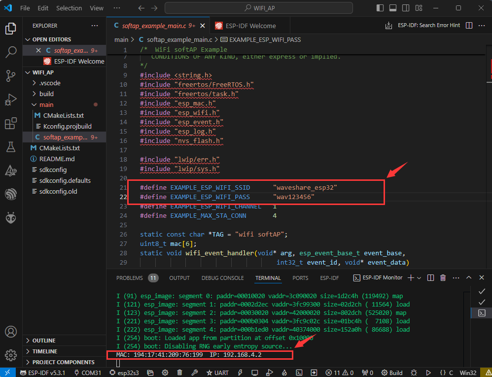
wifi_init_softap(void): This function is used to initialize the ESP32's Wi-Fi soft access point, including setting up the network interface, registering event handling functions, configuring soft AP parameters, and starting the soft AP.
Result demonstration
- When the chip is in AP mode, use the mobile phone to successfully connect to WIFI and the serial port will print the MACA address of the connected device and the IP address assigned to the device.
07_EX_GPIO
Demo description
- Test the basic functionality of extended IO and internal GPIO
Hardware connection
- Connect the board to the computer using a USB cable
- Use two cables to connect EXIO5 and EXIO6 together, and GPIO2 and GPIO1 together
Code analysis
I2C_master_Init(): Initialize I2C, which is the communication protocol for external IO extensionesp32_gpio_init(): Initialize GPIO, set GPIO1 and EXIO5 as output, and GPIO2 and EXIO6 as inputexample_GPIO_task(): Create an independent task to test the GPIO functionality, which can be modified by the user
Result demonstration
| GPIOx | GPIOy |
|---|---|
| GPIO1 | GPIO2 |
| EXIO5 | EXIO6 |
- The serial port monitor outputs "GPIO test passed" to indicate successful testing, output "GPIO test failed" to indicate failure
08_Li_ION_Test
Demo description
- By controlling GPIO, supply power to the lithium battery
Hardware connection
- Connect the board to the computer using a USB cable
Code analysis
BAT_GPIO_Init(): Use GPIO16 to control the power supply of the lithium battery, responsible for initializing GPIO16BAT_ON(): Enable the lithium battery to power the systemBAT_OFF(): Disable the lithium battery supply to power the system
Result demonstration
- After enabling the lithium battery power supply in the software, connect the lithium battery and then use the PWR button to power the lithium battery
09_LVGL_Test
Demo description
- Implement some multifunctional GUI interfaces on the screen by porting LVGL
Hardware connection
- Connect the board to the computer using a USB cable
Code analysis
lv_demo_widgets(): Verify the performance of the screen by testing the demo of LVGL
Code modification
- If you need to rotate the display by 90 degrees, you can find the macro definition
AMOLED_Rotatein the source file where themain()is located, and then choose of the two
#define AMOLED_Rotate  Rotate_90      //Landscape screen
#define AMOLED_Rotate  Rotate_NONO    //Portrait screen
10_FactoryProgram
Demo description
- Comprehensive demo for testing onboard functions. This routine needs to pay attention to the IDF version. Version 5.2.0 and above may not be able to scan the surrounding WiFi. If testing is needed, a lower version compilation or the BIN firmware we provide can be used
Hardware connection
- Connect the board to the computer using a USB cable
Result demonstration
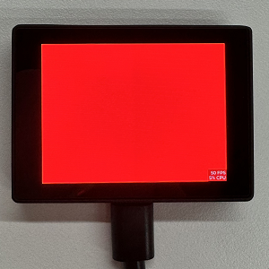
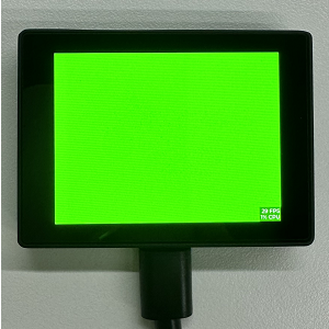
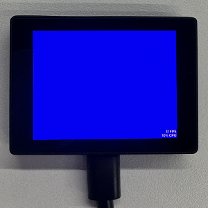
- Swipe left or right to switch pages, first display RGB colors every 1.5 seconds, which can be used to observe if there are any issues with the screen
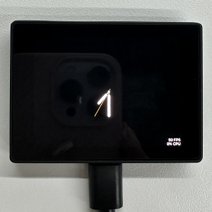
- After the RGB is displayed, it will automatically jump to the clock interface
- Swipe left on the interface, you can see that this page contains some built-in hardware information
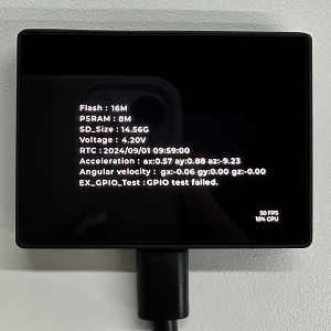
- Swipe left again, you can see that the interface is a functional interface
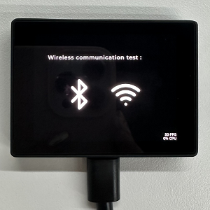
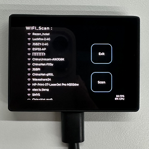
- You can click on the WIFI icon to enter the WIFI test interface, then click the Scan button to scan the surrounding WIFI
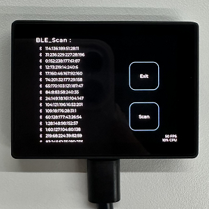
- Click Exit to return to the previous interface, then click the BLE flag to enter the BLE test interface, and then click the Scan button to scan the surrounding BLE
- Swipe left again to enter the brightness adjustment interface
Flash Firmware Flashing and Erasing
- The current demo provides test firmware, which can be used to test whether the onboard device functions properly by directly flashing the test firmware
- bin file path:
..\ESP32-S3-Touch-LCD-2.41-Demo\Firmware
Resources
Schematic Diagram
Demo
Dimensions and Appearance File
Datasheets
ESP32-S3
Other Components
Software Tools
Arduino
- Arduino IDE Official download link
- ESP32-Arduino official documentation
- Arduino-ESP32 offline component package
VScode
Firmware Flashing Tool
Other Resource Links
FAQ
Question: After the module downloads the demo and re-downloads it, why sometimes it can't connect to the serial port or the flashing fails?
- Long press the BOOT button, press RESET at the same time, then release RESET, then release the BOOT button, at this time the module can enter the download mode, which can solve most of the problems that can not be downloaded.
Question: Failed to set up the VSCode environment?
- First consider the network issue, try switching to another network
Question: Error when compiling an Arduino program?
- Check if the Arduino IDE -> Tools is correctly configured
Question: Is it stuck when sliding pictures displayed?
- Modify LVGL display cache to the full screen size
- Modify the LV_IMG_CACHE_DEF_SIZE option in the configuration to 1000 to achieve some optimization
Question: Can't display Chinese?
- Basic Chinese can be displayed, but if it is a rare character, it cannot be displayed
- You can transcode the required rare characters through the transcoding software, and then add them to the project font library
Question: How to deal with the first compilation of the program being extremely slow?
- It's normal for the first compilation to be slow, just be patient
Question: How to handle the display "waiting for download..." on the serial port after successfully ESP-IDF flashing?
- If there is a reset button on the development board, press the reset button; if there is no reset button, please power it on again
Question: What should I do if I can't find the AppData folder?
- Some AppData folders are hidden by default and can be set to show.
- English system: Explorer->View->Check "Hidden items"
- Chinese system: File Explorer -> View -> Display -> Check "Hidden Items"
Question: How do I check the COM port I use?
- Windows system:
①View through Device Manager: Press the Windows + R keys to open the "Run" dialog box; input devmgmt.msc and press Enter to open the Device Manager; expand the "Ports (COM and LPT)" section, where all COM ports and their current statuses will be listed.
②Use the command prompt to view: Open the Command Prompt (CMD), enter the "mode" command, which will display status information for all COM ports.
③Check hardware connections: If you have already connected external devices to the COM port, the device usually occupies a port number, which can be determined by checking the connected hardware.
- Linux system:
①Use the dmesg command to view: Open the terminal.
①Use the ls command to view: Enter ls /dev/ttyS* or ls /dev/ttyUSB* to list all serial port devices.
③Use the setserial command to view: Enter setserial -g /dev/ttyS* to view the configuration information of all serial port devices.
Question: Why does the program flashing fail when using a MAC device?
- Install MAC Driver and flash again.
Support
Monday-Friday (9:30-6:30) Saturday (9:30-5:30)
Email: services01@spotpear.com
[Tutorial Navigation]
- Overview
- Usage Instructions
- Working with Arduino
- Working with ESP-IDF
- Environment Setup
- Run the First ESP-IDF Demo
- New Project
- Create Demo
- Modify COM Port
- Modify Driver Object
- Other Status Bar Functions
- Compile, Flash and Serial Port Monitor
- Use the IDF Demos
- Demo
- Flash Firmware Flashing and Erasing
- Resources
- FAQ
- Question: After the module downloads the demo and re-downloads it, why sometimes it can't connect to the serial port or the flashing fails?
- Question: Failed to set up the VSCode environment?
- Question: Error when compiling an Arduino program?
- Question: Is it stuck when sliding pictures displayed?
- Question: Can't display Chinese?
- Question: How to deal with the first compilation of the program being extremely slow?
- Question: How to handle the display "waiting for download..." on the serial port after successfully ESP-IDF flashing?
- Question: What should I do if I can't find the AppData folder?
- Question: How do I check the COM port I use?
- Question: Why does the program flashing fail when using a MAC device?
- Support