


- sales/support
Google Chat:---
- sales
+86-0755-88291180
- sales01
sales@spotpear.com
- sales02
dragon_manager@163.com
- support
tech-support@spotpear.com
- CEO-Complaints
zhoujie@spotpear.com
- Only Tech-Support
WhatsApp:13246739196
- Purchase/Shipping/Refund
WhatsApp:13424403025
- HOME
- >
- ARTICLES
- >
- Common Moudle
- >
- ESP
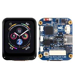
ESP32-S3-LCD-1.69 User Guide
Overview
Introduction
ESP32-S3-LCD-1.69 is a low-cost, high-performance MCU board designed by Waveshare. It is equipped with a 1.69inch capacitive LCD screen, a lithium battery charging chip, a six-axis sensor (three-axis accelerometer and a three-axis gyroscope), RTC and other peripherals, which are convenient for development and embedding into the product.
Features
- Equipped with high-performance Xtensa® 32-bit LX7 dual-core processor, up to 240 MHz main frequency
- Supports 2.4GHz Wi-Fi (802.11 b/g/n) and Bluetooth® 5 (BLE), with onboard antenna
- Built in 512KB of SRAM and 384KB ROM, with onboard 8MB PSRAM and an external 16MB Flash memory
- Built-in 1.69inch capacitive LCD screen with a resolution of 240×280, 262K colors for clear color pictures
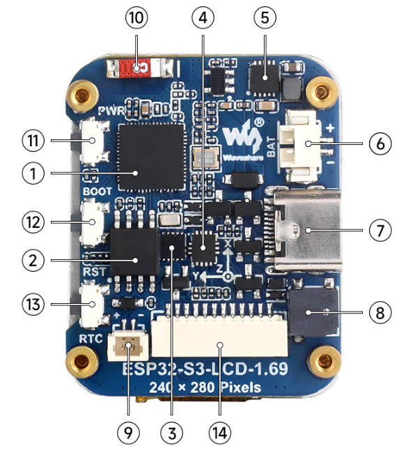
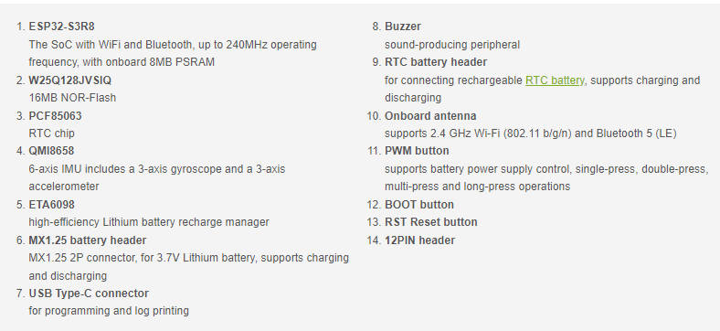
Onboard Resources
- Onboard patch antenna, as shown in the figure ⑩
- Onboard PCF85063 RTC clock chip and RTC battery interface, facilitating timing and scheduling functions, as shown in ③ and ⑨
- Onboard QMI8658 6-axis inertial measurement unit (IMU) containing a 3-axis gyroscope and a 3-axis accelerometer, as shown in ④
- Onboard ETA6098 high-performance Lithium battery charging chip, M1.25 Lithium battery interface, easy to install lithium batteries charge and discharge for long-term usage, as shown in ⑤ and ⑥
- Onboard buzzer can be utilized as an audio peripheral, as shown in ⑧
- Onboard Type-C interface, connect to ESP32-S3 USB for demo flashing and log printing, as shown in ⑦
- Onboard BOOT and RST function buttons, easy to reset and enter the download mode, as shown in ⑫ and ⑬
- Onboard function circuit button, can be customized as the power-on button, and can identify single pressing, double pressing, and long pressing, as shown in ⑪
Pinout Definition
When using the GPIO pins reserved on the ESP32-S3-LCD-1.69 board, it is important to pay attention to the wire colors and their corresponding functions to avoid damaging the development board due to wiring habits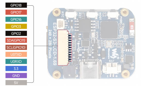
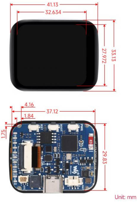
Dimensions
LCD and its Controller
- The built-in controller used in this LCD is ST7789V2, which is an LCD controller with 240 × RGB × 320 pixels, while the pixels of this LCD are 240(H) × RGB × 280(V). Hence, the LCD's internal RAM is not fully used
- This LCD supports 12-bit, 16-bit, and 18-bit per pixel input color formats, namely RGB444, RGB565, and RGB666 color formats, this demo uses RGB565 color format, which is also commonly used RGB Format
- This LCD uses a four-wire SPI communication interface, which can greatly save the GPIO port, and the communication speed will be faster
- The resolution of this module is 240(H) × RGB × 280(V), but sometimes it may not fully display your images as it is round in corners
SPI Communication Protocol
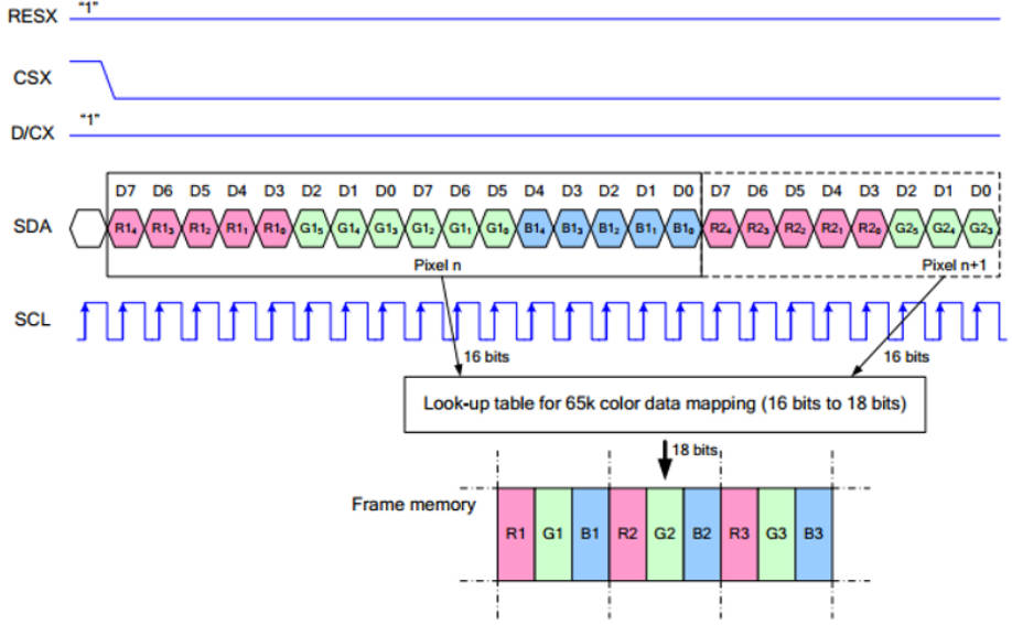
Note: The difference from the traditional SPI protocol is that the data line sent from the slave to the host is hidden because it only needs to be displayed. Please refer to Datasheet Page 66 for the table.
RESX is reset, it is pulled low when the module is powered on, usually set to 1;
CSX is the slave chip selection, and the chip will be enabled only when CS is low;
D/CX is the data/command control pin of the chip, when DC = 0, write command, when DC = 1, write data;
SDA is the transmitted data, that is, RGB data;
SCL is the SPI communication clock.
For SPI communication, data is transmitted with timing, that is, the combination of clock phase (CPHA) and clock polarity (CPOL):
The level of CPHA determines whether the data is collected on the first clock transition edge or the second clock transition edge of the serial synchronization clock. When CPHA = 0, data acquisition is performed on the first transition edge;
The level of CPOL determines the idle state level of the serial synchronous clock. When CPOL = 0, which is a low level.
As can be seen from the figure, at the first falling edge of SCLK it starts to transmit data, 8-bit data is transmitted in one clock cycle, using SPI0, bit-by-bit transmission, high bit first, and low bit last.
Usage Instructions
ESP32-S3-LCD-1.69 currently provides two development tools and frameworks, Arduino IDE and ESP-IDF, providing flexible development options, you can choose the right development tool according to your project needs and personal habits.
Development tools
Arduino IDEArduino IDE is an open source electronic prototyping platform, convenient and flexible, easy to get started. After a simple learning, you can start to develop quickly. At the same time, Arduino has a large global user community, providing an abundance of open source code, project examples and tutorials, as well as rich library resources, encapsulating complex functions, allowing developers to quickly implement various functions. | |
ESP-IDFESP-IDF, or full name Espressif IDE, is a professional development framework introduced by Espressif Technology for the ESP series chips. It is developed using the C language, including a compiler, debugger, and flashing tools, etc., and can be developed via the command lines or through an integrated development environment (such as Visual Studio Code with the Espressif IDF plugin). The plugin offers features such as code navigation, project management, and debugging. |
Each of these two development approaches has its own advantages, and developers can choose according to their needs and skill levels. Arduino are suitable for beginners and non-professionals because they are easy to learn and quick to get started. ESP-IDF is a better choice for developers with a professional background or high performance requirements, as it provides more advanced development tools and greater control capabilities for the development of complex projects.
Components preparation
- ESP32-S3-LCD-1.69 x1
- USB cable (Type-A to Type-C) x 1
Working with Arduino
This chapter introduces setting up the Arduino environment, including the Arduino IDE, management of ESP32 boards, installation of related libraries, program compilation and downloading, as well as testing demos. It aims to help users master the development board and facilitate secondary development.
Environment setup
Download and install Arduino IDE
- Click to visit the official website, select the corresponding system and system bit to download.
- Run the installer and install all by default.
Install Arduino-ESP32
- Regarding ESP32-related motherboards used with the Arduino IDE, the esp32 by Espressif Systems library must be installed first.
- It is generally recommended to use online installation. If online installation fails, use offline installation.
- To install the Arduino-ESP32 tutorial
- The ESP32-S3-LCD-1.69 development board comes with an offline package. Click here to download: esp32_package_3.0.5_arduino offline package
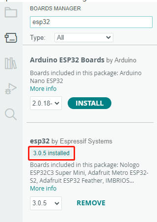
| Board name | Board installation requirements | Version number requirements |
|---|---|---|
| ESP32-S3-LCD-1.69 | "Install Offline" / "Install Online” | 3.0.5 and above |
Install library
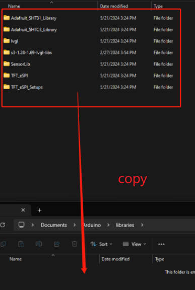
- When installing Arduino libraries, there are usually two ways to choose from: Install online and Install offline. If the library installation requires offline installation, you must use the provided library file
For most libraries, users can easily search and install them through the online library manager of the Arduino software. However, some open-source libraries or custom libraries are not synchronized to the Arduino Library Manager, so they cannot be acquired through online searches. In this case, users can only manually install these libraries offline. - For library installation tutorial
- ESP32-S3-LCD-1.69 library file is stored in the sample program, click here to jump: ESP32-S3-LCD-1.69 Demo
| Library Name | Description | Version | Library Installation Requirements |
|---|---|---|---|
| GFX_Library_for_Arduino | GFX graphical library for ST7789 | v1.4.9 | “Install Online” or “Install Offline” |
| lvgl | LVGL graphical library | v8.4.0 | "Install Online" requires copying the demos folder to src after installation. “Install Offline” is recommended |
| Mylibrary | Development board pin macro definition | —— | “Install Offline” |
| SensorLib | PCF85063, QMI8658 sensor driver library | v0.2.1 | “Install Online” or “Install Offline” |
| lv_conf.h | LVGL configuration file | —— | “Install Offline” |
Demos
| Demo | Basic Description | Dependency Library |
|---|---|---|
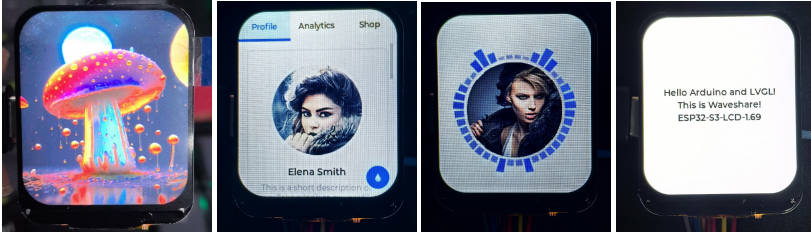
| 01_HelloWorld | Demonstrates the basic graphics library functions and can also be used to test the basic performance of display screens and the display effect of random text | GFX_Library_for_Arduino |
| 02_GFX_AsciiTable | Prints ASCII characters in rows and columns on the display screen according to the screen size | GFX_Library_for_Arduino |
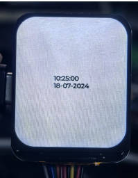
| 03_GFX_PCF85063_simpleTime | Displays the current time | SensorLib, GFX_Library_for_Arduino |
| 04_GFX_ESPWiFiAnalyzer | Draws the WiFi band signal strength on the ST7789 display | GFX_Library_for_Arduino |
| 05_GFX_Clock | A simple ST7789 clock example, implemented through basic pointer marking and time management | GFX_Library_for_Arduino |
| 06_LVGL_Measuring_voltage | The voltage is measured by a voltage divider on the board, and the analog value is read using GPIO1, then the battery voltage is calculated using the voltage divider formula | LVGL |
| 07_LVGL_PCF85063_simpleTime | Use the PCF85063 RTC module to display the current time on the ST7789 display under LVGL | LVGL, SensorLib |
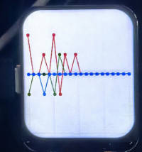
| 08_LVGL_QMI8658_ui | Display graphics using LVGL and communicate with the QMI8658 IMU to obtain accelerometer and gyroscope data | LVGL, SensorLib |
| 09_LVGL_Keys_Bee | LVGL | |
| 10_LVGL_Arduino | LVGL demonstration | LVGL |
- ESP32-S3-LCD-1.69 supports direct model selection
01_HelloWorld
Hardware connection
- Connect the board to the computer using a USB cable
Code analysis
- Initialize the display:
if (!gfx->begin()) {
   USBSerial.println("gfx->begin() failed!");
}- Clear the screen and display text:
gfx->fillScreen(BLACK);
 gfx->setCursor(10, 10);
 gfx->setTextColor(RED);
gfx->println("Hello World!");- GIF display:
gfx->setCursor(random(gfx->width()), random(gfx->height()));
 gfx->setTextColor(random(0xffff), random(0xffff));
 gfx->setTextSize(random(6), random(6), random(2));
 gfx->println("Hello World!");
02_GFX_AsciiTable
Hardware connection
- Connect the board to the computer using a USB cable
Code analysis
- Initialize the display:
if (!gfx->begin()) {
   USBSerial.println("gfx->begin() failed!");
}- Calculate rows and columns and label them with numbers: Here the number of columns and rows that can be displayed is calculated according to the size of the display. Then use two loops separately, set different text colors, and print the numbers of rows and columns on the display so that the position of the characters can be easily determined when drawing the ASCII characters in the future.
int numCols = LCD_WIDTH / 8;
int numRows = LCD_HEIGHT / 10;

// Label the line number
gfx->setTextColor(GREEN);
for (int x = 0; x < numRows; x++) {
    gfx->setCursor(10 + x * 8, 2);
    gfx->print(x, 16);
}

// Label the column number
gfx->setTextColor(BLUE);
for (int y = 0; y < numCols; y++) {
    gfx->setCursor(2, 12 + y * 10);
    gfx->print(y, 16);
}- Draw the ASCII character table:
char c = 0;
for (int y = 0; y < numRows; y++) {
    for (int x = 0; x < numCols; x++) {
        gfx->drawChar(10 + x * 8, 12 + y * 10, c++, WHITE, BLACK);
    }
}
03_GFX_PCF85063_simpleTime
Hardware connection
- Connect the board to the computer using a USB cable
Code analysis
loop():- Get the current time first, and if this time is different from the last displayed time, perform the following operations:
- Clear the area for the last displayed time, achieve this by filling a rectangle, so that there won't be overlapping when updating the time display.
- Set the text color to black and the text size to 3.
- Call the getCenteredX function to calculate the X coordinate of the current time string centered on the screen.
- Set the cursor position and print the current time string to update the display of the time.
- Copy the current time string to the previous Timestamp string to determine if the time has changed next time.
04_GFX_ESPWiFiAnalyzer
Hardware connection
- Connect the board to the computer using a USB cable
Code analysis
setup():
Initialize serial port communication;
Set WiFi to site mode and disconnect;
Initialize the display, obtain the screen size, and calculate various drawing parameters;
Set the screen background to black and draw the title bar.
loop():
Scan WiFi networks and get network information, including channels, RSSI, BSSID, and SSID;
Count the number of networks, noise levels, and peak signal strength on each channel;
Clear old graphics and draw new ones based on the scan results, including signal strength ellipses and network information text;
Print the number of networks scanned and the channel with the least noise;
Draw graph baselines and channel numbering;
Enter the low-power mode according to the conditions.
05_GFX_Clock
Hardware connection
- Connect the board to the computer using a USB cable
Code analysis
- Draw hour, minute and second hands:
void redraw_hands_cached_draw_and_erase() {
    gfx->startWrite();
    draw_and_erase_cached_line(center, center, nsx, nsy, SECOND_COLOR, cached_points, sHandLen + 1, false, false);
    draw_and_erase_cached_line(center, center, nhx, nhy, HOUR_COLOR, cached_points + ((sHandLen + 1) * 2), hHandLen + 1, true, false);
    draw_and_erase_cached_line(center, center, nmx, nmy, MINUTE_COLOR, cached_points + ((sHandLen + 1 + hHandLen + 1) * 2), mHandLen + 1, true, true);
    gfx->endWrite();
}
06_LVGL_Measuring_voltage
Hardware connection
- Connect the board to the computer using a USB cable
Code analysis
my_print(): Used for LVGL log output, if LVGL log function is enabled, this function will print the log information to the serial portmy_disp_flush(): Responsible for refreshing the LVGL drawing buffer content to the display screenexample_increase_lvgl_tick(): A timer callback function that is used to notify LVGL about the passage of timeexample_increase_reboot(): Another timer callback function that counts and may trigger a system reboot after a certain number of times
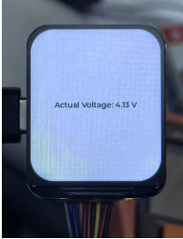
Result demonstration
- The voltage is measured by a voltage divider on the board, and the analog value is read using GPIO1, then the battery voltage is calculated using the voltage divider formula
07_LVGL_PCF85063_simpleTime
Hardware connection
- Connect the board to the computer using a USB cable
Code analysis
setup():
Initialize serial communication, prepare possible serial debugging at baud rate of 115200;
Try to connect the PCF85063 real-time clock chip, if the connection fails, enter an infinite loop;
Set the initial time of the real-time clock to September 24, 2024, 11:09:41;
Initialize the display and set the screen brightness;
Initialize LVGL and register the logging output function (if logging is enabled);
Configure the LVGL display driver and drawing buffer, as well as initialize the input device driver (which is a virtual pointer input device driver);
Create a timer to periodically trigger the LVGL clock update
Create a label and set the initial text to “Initializing...”
loop():
Call lv_timer_handler to have LVGL handle graphical interface tasks;
Check the time for updates every second. If it has been updated, obtain the current time of the real-time clock, output it through the serial port, format the time into a specific format, update the text content of the label, and set the label's font to lv_font_montserrat_40.
Result demonstration
08_LVGL_QMI8658_ui
Hardware connection
- Connect the board to the computer using a USB cable
Code analysis
my_disp_flush():
This function is the refresh function of the LVGL display driver. It is responsible for refreshing the LVGL drawing buffer content to the display screen;
Based on different color formats, call the corresponding functions of the gfx object to draw the bitmap to a specific area;
Finally, LVGL is notified that the refresh of the display has been completed.
loop():
Call lv_timer_handler to have LVGL handle graphical interface tasks;
Check if new data is ready for the QMI (QMI8658 sensor object). If available, attempt to acquire acceleration data and gyroscope data, and output through the serial port;
At the same time, the acceleration data is updated to the LVGL graph to show the change of acceleration on the three axes in real time;
Increase the frequency of data polling with delay(20) to ensure that sensor data is captured in a timely manner and the display is updated.
Result demonstration
- LVGL is used for graphical display, communicating with the QMI8658 IMU to obtain accelerometer and gyroscope data
09_LVGL_Keys_Bee
Hardware connection
- Connect the board to the computer using a USB cable
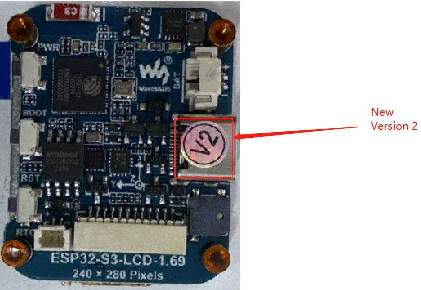
Comparison of old and new versions
- This function button was designed to address the issue of fewer functions on external device buttons. In version V2, we made some adjustments:
| Peripheral | Old version | New version |
|---|---|---|
| Buzzer (Buzz) | GPIO33 | GPIO42 |
| RTC interrupt (RTC_INT) | GPIO41 | GPIO39 |
| Power control (SYS_EN) | GPIO35 | GPIO41 |
| Power control (SYS_OUT) | GPIO36 | GPIO40 |
The principle is as follows:
Pressing PWR allows battery power, initiating the system. At this point, the system should define SYS_EN to continuously output a high voltage level to maintain the powered-on effect. Releasing PWR will not cause a power cut. The function of PWR at this time is to lower SYS_OUT. The system detects actions such as pressing, double pressing, and long pressing on SYS_OUT, enabling customizable power-off control operations. For instance, in a long press mode, setting SYS_EN to a low level to disconnect the battery power completes the use of the multi-purpose buttons.
Code analysis
loop():
Call lv_timer_handler to have LVGL handle graphical interface tasks;
Read the status of the input pin, and perform debouncing processing;
Based on the state of the button (pressed or released) and the time interval, determine whether it is a single click, double click, or long press event, and update the label text on the display to show the corresponding event information;
At the same time, for the long press event, the buzzer will be triggered, and when released, the buzzer will be stopped and the specific output pin will be set to a low level.
10_LVGL_Arduino
Hardware connection
- Connect the board to the computer using a USB cable
Result demonstration
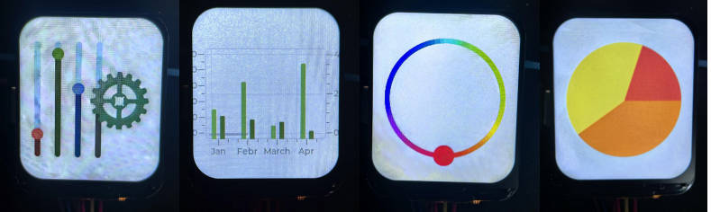
Use of LVGL components
When developing using the LVGL framework, you can call the components according to the component instructions provided in the LVGL official documentation LVGL8.3 Documents
Below is a case study of LVGL actual components in the Arduino IDE
Working with ESP-IDF
This chapter introduces setting up the ESP-IDF environment setup, including the installation of Visual Studio and the Espressif IDF plugin, program compilation, downloading, and testing of example programs, to assist users in mastering the development board and facilitating secondary development.
Environment setup
Download and install Visual Studio
- Open the download page of VScode official website, choose the corresponding system and system bit to download
- After running the installation package, the rest can be installed by default, but here for the subsequent experience, it is recommended to check boxes 1, 2, and 3
- After the first two items are enabled, you can open VSCode directly by right-clicking files or directories, which can improve the subsequent user experience.
- After the third item is enabled, you can select VSCode directly when you choose how to open it.
Install Espressif IDF Plug-in
- It is generally recommended to use Install Online. If online installation fails due to network factor, use Install OIffline.
- For more information about how to install the Espressif IDF plug-in, see Install Espressif IDF Plug-in
Demos
| Demo | Basic Description |
|---|---|
| 01_ESP_IDF_ST7789 | Drive the st7789 screen through SPI to display text, pictures, drawings and other functions |
| 02_ESP_IDF_ST7789_LVGL | Display LVGLdemo, use LVGL to display picture data |
| 03_PCF85063 | Use a simple method to drive the PCF85063 for time storage and reading functionality |
| 04_QMI8658 | Use ESP-IDF to port SensorLib, then use the ported SensorLib to drive qmi8658 to obtain gyroscope-related data |
01_ESP_IDF_ST7789
Hardware connection
- Connect the board to the computer using a USB cable
Code analysis
ST7789():
Initialize various font objects, ready for displaying text on the screen;
Initialize TFT_t objects associated with the ST7789 display, including setting SPI pins and display parameters via spi_master_init and lcdInit functions;
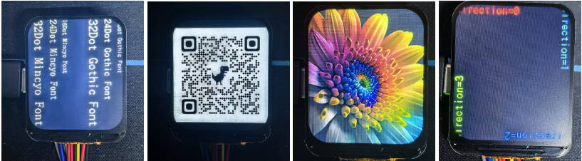
Enter an infinite loop and call various graphics test functions (such as FillTest, ColorBarTest, etc.) and font display test functions in turn to display different graphics and font display effects on the display. There is a period of time between each test to observe the results.
Result demonstration
- Drive the st7789 screen through SPI to display text, pictures, drawings and other functions
02_ESP_IDF_ST7789_LVGL
Hardware connection
- Connect the board to the computer using a USB cable
Code analysis
app_lcd_init():
Configure and initialize the backlight pin for the LCD;
Initialize the SPI bus for communication with the LCD;
Create a panel IO object for the LCD and configure SPI-related parameters;
Install the LCD driver, create the LCD panel object, and perform some initialization operations, such as reset, turn on the display, set the mirror, etc.;
Turn on the LCD backlight.
app_lcd_init():
Initialize LVGL and set parameters such as task priority, stack size, and timer period;
Configure the parameters of the LCD display and add it to the LVGL as a display device. In this way, LVGL can draw a graphical interface on this display.
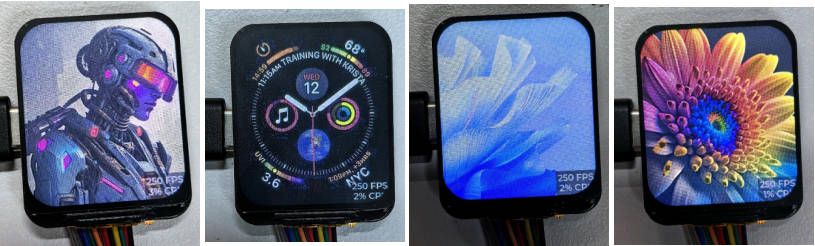
Result demonstration
- LVGL displays picture data
03_PCF85063
Hardware connection
- Connect the board to the computer using a USB cable
Code analysis
rtc_get_time():
This function is used to read the current time from the RTC (real-time clock chip, here it is assumed to be PCF85063). It reads 7 bytes of data from a specific register address by calling the rtc_read_reg function, representing seconds, minutes, hours, days, days of the week, months, and years.
It converts the read BCD format data to decimal format and prints out the current time. If the read operation fails, an error message is printed and an error code is returned.
rtc_set_time():
This function is used to set the time of the RTC. It accepts hours, minutes, seconds, days, months, and years as parameters, converts these decimal data into BCD format, and forms an array.
It sets the time of the RTC by calling the rtc_write_reg function to write this array to the beginning of the specific register address of the RTC. If the write is successful, ESP_OK is returned; otherwise, the corresponding error code is returned.
Result demonstration
- It drives PCF85063 to perform time storage reading
04_QMI8658
Hardware connection
- Connect the board to the computer using a USB cable
Code analysis
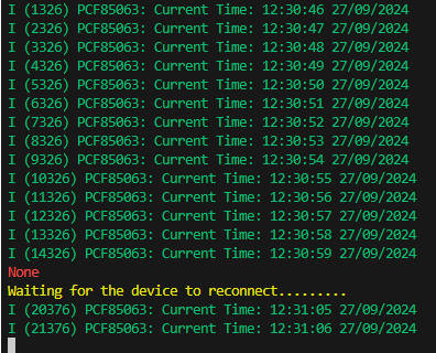
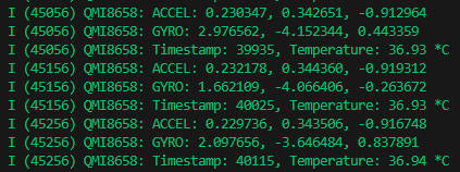
read_sensor_data():
Use the qmi.getAccelerometer function to read the accelerometer data, and if the reading is successful, print the data for the three axes of the accelerometer. If the read fails, an error message is printed;
Use the qmi.getGyroscope function to read the gyroscope data, and if the read is successful, print the data for the three axes of the gyroscope. If the read fails, an error message is printed;
Use the functions qmi.getTimestamp and qmi.getTemperature_C to respectively obtain the timestamp and temperature from the sensor, and print them out.
If the data is not ready, print a warning message. Then wait for a period of time and cycle again to check whether the data is ready.
Result demonstration
- Get gyroscope-related data
Resources
Schematic diagram
3D Diagrams
Demos
Datasheets
ESP32-S3
Other components
Software tools
Arduino
VScode
Other resource link
- ESP32-Arduino official documentation
- ESP32-Arduino official resources
- ESP-IDF official resources
- LVGL official documentation
FAQ
Question: Which version is my development board?
After receiving the goods, please check whether there is a QC label on the board, if there is a V2QC label, it is a new version of V2. This version has a slightly different pin definition.
Question: The board is too hot, what's the cause? How to solve it?
1. When you find the board is hot, please make sure to pull down the GPIO33 first, and pull down the buzzer pin, otherwise the passive buzzer is like a resistor that consumes power all the time, which leads to the LDO current pressure to be high and it will be hot.
2. If you also use WiFi/Bluetooth function, overheating cannot be avoided. ESP32-S3 opens wireless function and the related power consumption will increase, leading to heat generation.
3. In the Arduino IDE environment, turning on the PSRAM, using external Flash and pulling down the GPIO33 to enable pins will still cause a lot of heat, it is recommended to use a low-power program to play!
Question: Why does the flashing fail?
1. When the serial port is occupied, programming will fail. Close the serial port monitor and re-program. 2. When the ESP32 program crashes, the flashing will fail. At this time, the development module needs to be completely powered off, hold down BOOT and then power on to enter the strong download mode before flashing. After flashing, it will not automatically exit the download mode, so you need to power off and restart again.
Question: How to check the COM port you are using?
Windows: (1) View through Device Manager: Press the Windows + R keys to open the Run dialog box; type devmgmt.msc and press enter to open Device Manager; expand the Ports (COM and LPT) section, which will list all COM ports and their current status. (2) Use Command Prompt to view: Open Command Prompt (CMD); Enter the mode command, which will display status information for all COM ports. (3) Check the hardware connection: If you have connected an external device to the COM port, usually the device will occupy a port number, and you can determine which port is used by looking at the connected hardware. Linux: (1) Use the dmesg command to view: Open the terminal. (2) Use the ls command to view: Enter ls /dev/ttyS* or ls /dev/ttyUSB* to list all serial devices. (3) Use setserial command to view: Enter setserial -g /dev/ttyS* to view the configuration information of all serial devices.
Question: How do I port the provided lib libraries? Or how to develop my own LCD screen? How to drive?
The LCD screen display chip used in this product is ST7789V2, and the touch chip is CST816T, there are drivers for the two chips in the libs we provided, for the display driver, please refer to TFT_eSPI enable, and for the touch driver, please refer to the Arduino_LVGL sample demo.
Question: Can you help me with the code? Can you help me change the code?
This product is a development board and is not an end product. The product ecology is ESP32 core, and the ecology is very mature, the development environment is also very friendly, we do not assist in modifying the code, so creators, and geeks can play with their own DIY ability, if you have any questions you can ask the development engineers to answer for you.
If you think our products are good, and hope to batch customized hardware, customized shell, customized software, etc., welcome to contact the development engineers!
Support
Monday-Friday (9:30-6:30) Saturday (9:30-5:30)
Email: services01@spotpear.com
[Tutorial Navigation]
- Overview
- Introduction
- Features
- Onboard Resources
- Pinout Definition
- Dimensions
- LCD and its Controller
- SPI Communication Protocol
- Usage Instructions
- Working with Arduino
- Working with ESP-IDF
- Resources
- FAQ
- Question: Which version is my development board?
- Question: The board is too hot, what's the cause? How to solve it?
- Question: Why does the flashing fail?
- Question: How to check the COM port you are using?
- Question: How do I port the provided lib libraries? Or how to develop my own LCD screen? How to drive?
- Question: Can you help me with the code? Can you help me change the code?
- Support