- sales/support
Google Chat:---
- sales
+86-0755-88291180
- sales01
sales@spotpear.com
- sales02
dragon_manager@163.com
- support
tech-support@spotpear.com
- CEO-Complaints
zhoujie@spotpear.com
- Only Tech-Support
WhatsApp:13246739196
- Purchase/Shipping/Refund
WhatsApp:13424403025
- HOME
- >
- ARTICLES
- >
- Common Moudle
- >
- LCD
8. Backlight control User Guide
Backlight control
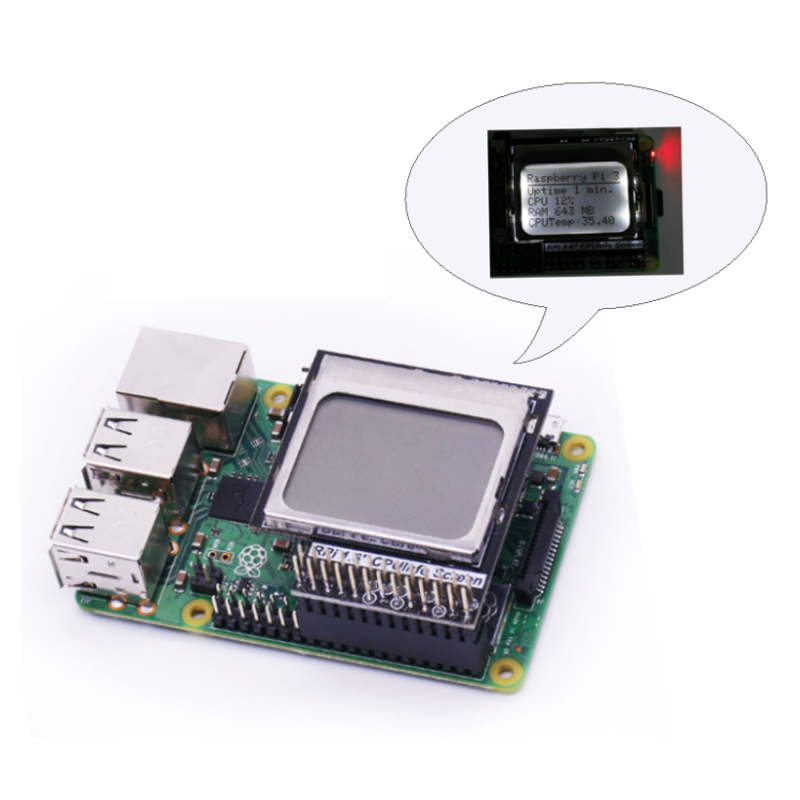
After CPU Info LCD screen is correctly inserted into the Raspberry Pi, you need to compile and run the program to display it normally.
This experiment controls the backlight effect through the program: the backlight will flash every 0.5 seconds.
1. Welding The BL_JMP of 1.6 LCD
!!!Note: Before welding BL_JMP, you must turn BackLight Swith to OFF. Otherwise, when GPIO7 outputs high level (3.3V), it will cause a short circuit. Because the short circuit current is too large, it is likely to burn out the Raspberry Pi and the display.
Therefore, users who need to use software to control the backlight effect will turn the switch to the OFF position in reverse order.
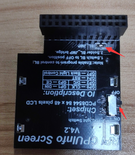
2. Install the wringPi library
CPU Info LCD screen is used for data communication through the GPIO port of the Raspberry Pi, so we must install the wiringPi library file.
Enter the following command to install the wringPi library. Users who have already installed the wiringPi library can ignore this step.
cd ~
git clone git://git.drogon.net/wiringPi
cd wiringPi
./build
3.Install Drive
1) Transfer the driver file to the Raspberry Pi
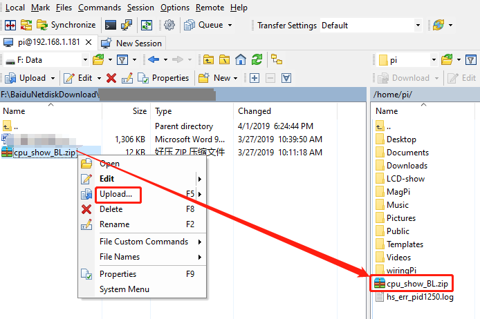
You need to install the Winscp tool on your computer. After connecting to the Raspberry Pi, transfer the cpu_show_BL.zip package from this folder to the pi directory of the Raspberry Pi.
As shown blew, drag and drop cpu_show_BL.zip directly into the Raspberry Pi system.
2 )Extract file
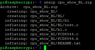
Open the Raspberry Pi terminal and find the cpu_show_BL.zip file.
Enter command:
ls

Enter command:
unzip cpu_show_BL.zip
3) Enter the program folder
cd ~/cpu_show_BL
ls

4) Compile file
Enter command:
gcc -o bl bl.c PCD8544.c -lwiringPi

5) Running procedure
Enter command:
./bl

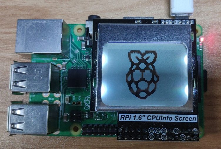
The Raspberry Pi icon is displayed on the CPU Info screen and the backlight flashes every 0.5s
4.Code analysis
Enter command:
nano bl.c
This command is to open bl.c
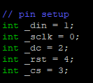
1) The following sections are the LCD pin settings:
2)Main function
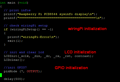
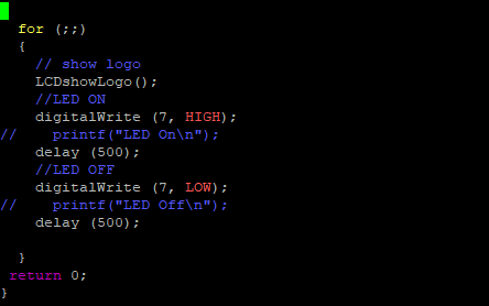
3)The front part is the initialization program and the prompt information; the latter part is a for loop.
Note: If you have added a boot-up user, first move the xx.desktop file displayed on the 1.6-inch screen in the /home/pi/.config/autostart folder to the pi directory.
If you do not close a program that has already been run, the screen will always change due to conflicts after the program runs.
For example, there is a file driver.desktop that drives a 1.6-inch screen in the /home/pi/.config/autostart folder.

We need to move start.desktop to the pi directory:
Enter command:
mv /home/pi/.config/autostart/start.desktop /home/pi
Then we can enter command:
sudo reboot
This command is to restart the Raspberry Pi.