- sales/support
Google Chat:---
- sales
+86-0755-88291180
- sales01
sales@spotpear.com
- sales02
dragon_manager@163.com
- support
tech-support@spotpear.com
- CEO-Complaints
zhoujie@spotpear.com
- Only Tech-Support
WhatsApp:13246739196
- Purchase/Shipping/Refund
WhatsApp:13424403025
- HOME
- >
- ARTICLES
- >
- Hot Articles
- >
- Raspberry Pi
RPi Tutorial Series: SPI User Guide
SPI is another communication interface on Raspberry Pi. This section explains how to use a SPI interface on the Pi.
Enable SPI
Configure your Pi and enable the SPI
sudo raspi-config
Select Advanced Options -> SPI -> <YES> to enable the SPI driver by kernel. Then you can check if the SPI is enabled:
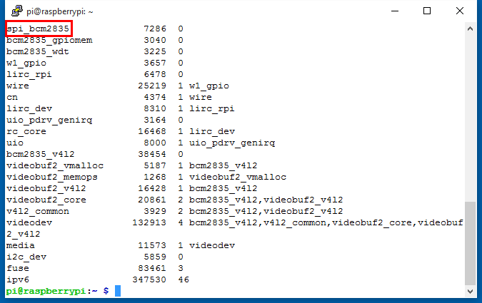
lsmod
If SPI enabled, the terminal echoes an spi-bcm2835 device. You can check the GPIO with the command:
gpio readall
you get:
 +-----+-----+---------+------+---+---Pi 3---+---+------+---------+-----+-----+
 | BCM | wPi |   Name  | Mode | V | Physical | V | Mode | Name    | wPi | BCM |
 +-----+-----+---------+------+---+----++----+---+------+---------+-----+-----+
 |     |     |    3.3v |      |   |  1 || 2  |   |      | 5v      |     |     |
 |   2 |   8 |   SDA.1 |   IN | 1 |  3 || 4  |   |      | 5V      |     |     |
 |   3 |   9 |   SCL.1 |   IN | 1 |  5 || 6  |   |      | 0v      |     |     |
 |   4 |   7 | GPIO. 7 |   IN | 1 |  7 || 8  | 0 | IN   | TxD     | 15  | 14  |
 |     |     |      0v |      |   |  9 || 10 | 1 | IN   | RxD     | 16  | 15  |
 |  17 |   0 | GPIO. 0 |   IN | 0 | 11 || 12 | 0 | IN   | GPIO. 1 | 1   | 18  |
 |  27 |   2 | GPIO. 2 |   IN | 0 | 13 || 14 |   |      | 0v      |     |     |
 |  22 |   3 | GPIO. 3 |   IN | 0 | 15 || 16 | 0 | IN   | GPIO. 4 | 4   | 23  |
 |     |     |    3.3v |      |   | 17 || 18 | 0 | IN   | GPIO. 5 | 5   | 24  |
 |  10 |  12 |    MOSI |   IN | 0 | 19 || 20 |   |      | 0v      |     |     |
 |   9 |  13 |    MISO |   IN | 0 | 21 || 22 | 0 | IN   | GPIO. 6 | 6   | 25  |
 |  11 |  14 |    SCLK |   IN | 0 | 23 || 24 | 1 | IN   | CE0     | 10  | 8   |
 |     |     |      0v |      |   | 25 || 26 | 1 | IN   | CE1     | 11  | 7   |
 |   0 |  30 |   SDA.0 |   IN | 1 | 27 || 28 | 1 | IN   | SCL.0   | 31  | 1   |
 |   5 |  21 | GPIO.21 |   IN | 1 | 29 || 30 |   |      | 0v      |     |     |
 |   6 |  22 | GPIO.22 |   IN | 1 | 31 || 32 | 0 | IN   | GPIO.26 | 26  | 12  |
 |  13 |  23 | GPIO.23 |   IN | 0 | 33 || 34 |   |      | 0v      |     |     |
 |  19 |  24 | GPIO.24 |   IN | 0 | 35 || 36 | 0 | IN   | GPIO.27 | 27  | 16  |
 |  26 |  25 | GPIO.25 |   IN | 0 | 37 || 38 | 0 | IN   | GPIO.28 | 28  | 20  |
 |     |     |      0v |      |   | 39 || 40 | 0 | IN   | GPIO.29 | 29  | 21  |
 +-----+-----+---------+------+---+----++----+---+------+---------+-----+-----+
 | BCM | wPi |   Name  | Mode | V | Physical | V | Mode | Name    | wPi | BCM |
 +-----+-----+---------+------+---+---Pi 3---+---+------+---------+-----+-----+
The SPI interface composed with these pins: SCLK (Clock), CE (Chip select), MOMI (Master Out Master In) and MIMO (Master In Master Out).
SPI Programming
A 0.96" OLED is embedded within Pioneer600. The OLED is communicated with the MCU via SPI and you can download the examples from File:Pioneer600-Code.tar.gz. This example is too long to paste, so we just explain some spi functions briefly. See detailed program in the demo code directory Pioneer600/OLED/. You should install some specific libraries before trying these examples, see: Libraries Installation for RPi.
BCM2835
- bcm2835_spi_begin(); // Start SPI operations. Forces RPi SPI0 pins P1-19 (MOSI), P1-21 (MISO), P1-23 (CLK), P1-24 (CE0) and P1-26 (CE1) to alternate function ALT0, which enables those pins for SPI interface. You should call bcm2835_spi_end() when all SPI funcitons are complete to return the pins to their default functions. See: http://www.airspayce.com/mikem/bcm2835/group__spi.html
- bcm2835_spi_setBitOrder(BCM2835_SPI_BIT_ORDER_MSBFIRST); // Set bit order as MSB First
- bcm2835_spi_setDataMode(BCM2835_SPI_MODE0); // Sets the SPI data mode, CPOL = 0, CPHA = 0
- bcm2835_spi_setClockDivider(BCM2835_SPI_CLOCK_DIVIDER_128); // Sets the SPI clock divider
- bcm2835_spi_chipSelect(BCM2835_SPI_CS0); // Sets the chip select pin(s) When an bcm2835_spi_transfer() is made,
- bcm2835_spi_setChipSelectPolarity(BCM2835_SPI_CS0, LOW); // Sets the chip select pin CS0 polarity as active LOW.
- bcm2835_spi_transfer(uint_t value); // Transfers one byte
- bcm2835_spi_transfernb(char *tbuf,char *rbuf,uint32_t len); // Transfers any number of bytes