- sales/support
Google Chat:---
- sales
+86-0755-88291180
- sales01
sales@spotpear.com
- sales02
dragon_manager@163.com
- support
tech-support@spotpear.com
- CEO-Complaints
zhoujie@spotpear.com
- Only Tech-Support
WhatsApp:13246739196
- Purchase/Shipping/Refund
WhatsApp:13424403025
- HOME
- >
- ARTICLES
- >
- LuckFox
- >
- LuckFox Pico
Luckfox Pico RV1103【Tutorial on how to use PWM】
Due to pin multiplexing on the LuckFox Pico and LuckFox Pico Plus, there may be conflicts in pin functionality, so PWM functionality cannot be enabled by default for all pins.
】Use the GPIO sysfs interface to control PWM:
1] View the default enabled PWM interfaces:
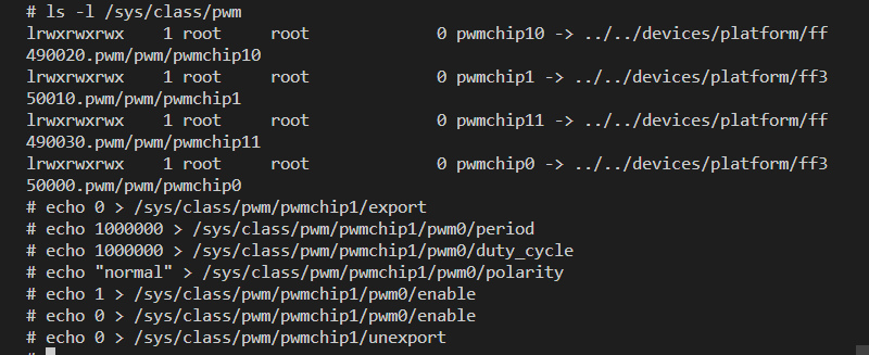
# ls -l /sys/class/pwm
lrwxrwxrwx 1 root root 0 pwmchip10 -> ../../devices/platform/ff490020.pwm/pwm/pwmchip10
lrwxrwxrwx 1 root root 0 pwmchip1 -> ../../devices/platform/ff350010.pwm/pwm/pwmchip1
lrwxrwxrwx 1 root root 0 pwmchip11 -> ../../devices/platform/ff490030.pwm/pwm/pwmchip11
lrwxrwxrwx 1 root root 0 pwmchip0 -> ../../devices/platform/ff350000.pwm/pwm/pwmchip0
2] Test PWM. Export PWM1_M0 (GPIO0_A4_d) to the user space:
echo 0 > /sys/class/pwm/pwmchip1/export
3] Set the PWM period unit to ns. For example, the period of a 1KHz frequency is 1000000ns:
echo 1000000 > /sys/class/pwm/pwmchip1/pwm0/period
4] Set the duty cycle:
#Set the duty cycle to 10% (with a period of 100,000 nanoseconds and a duration of 10,000 nanoseconds).
echo 100000 > /sys/class/pwm/pwmchip1/pwm0/duty_cycle
echo 200000 > /sys/class/pwm/pwmchip1/pwm0/duty_cycle
echo 300000 > /sys/class/pwm/pwmchip1/pwm0/duty_cycle
echo 400000 > /sys/class/pwm/pwmchip1/pwm0/duty_cycle
echo 500000 > /sys/class/pwm/pwmchip1/pwm0/duty_cycle
echo 600000 > /sys/class/pwm/pwmchip1/pwm0/duty_cycle
echo 700000 > /sys/class/pwm/pwmchip1/pwm0/duty_cycle
echo 800000 > /sys/class/pwm/pwmchip1/pwm0/duty_cycle
echo 900000 > /sys/class/pwm/pwmchip1/pwm0/duty_cycle
# Set the duty cycle to 100% (with a period of 1,000,000 nanoseconds and a duration of 1,000,000 nanoseconds).
echo 1000000 > /sys/class/pwm/pwmchip1/pwm0/duty_cycle
#Set the duty cycle to 0, which is equivalent to stopping the duty cycle output.
echo 0 > /sys/class/pwm/pwmchip1/pwm0/duty_cycle
5] Set the normal PWM polarity:
#Set the normal PWM polarity:
echo "normal" > /sys/class/pwm/pwmchip1/pwm0/polarity
#Set the inverted PWM polarity:
echo "inversed" > /sys/class/pwm/pwmchip1/pwm0/polarity
6] Enable PWM :
echo 1 > /sys/class/pwm/pwmchip1/pwm0/enable
7] Disable PWM :
echo 0 > /sys/class/pwm/pwmchip1/pwm0/enable
8] Disable exporting PWM to user space:
echo 0 > /sys/class/pwm/pwmchip1/unexport
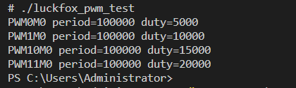
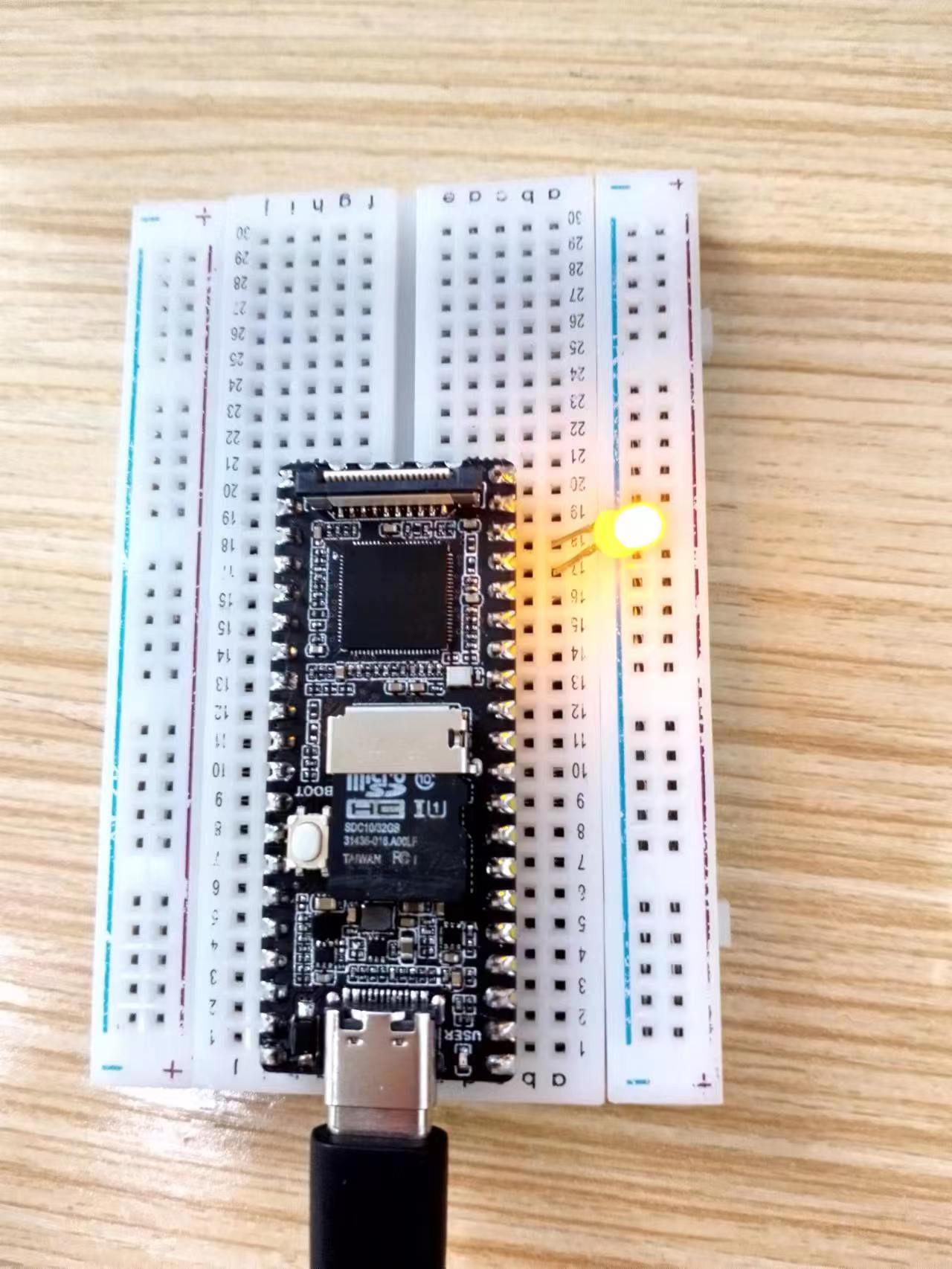
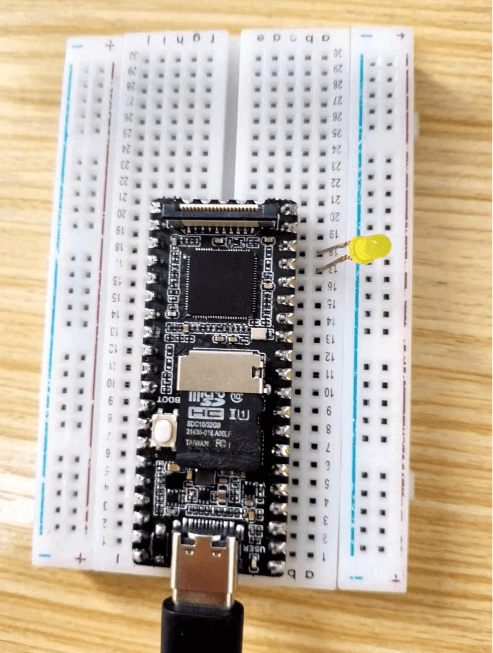
9] Screenshot of the operation process: