- sales/support
Google Chat:---
- sales
+86-0755-88291180
- sales01
sales@spotpear.com
- sales02
dragon_manager@163.com
- support
tech-support@spotpear.com
- CEO-Complaints
zhoujie@spotpear.com
- Only Tech-Support
WhatsApp:13246739196
- Purchase/Shipping/Refund
WhatsApp:13424403025
- HOME
- >
- ARTICLES
- >
- LuckFox
- >
- LuckFox Pico
Luckfox Pico RV1103【Tutorial on how to use GPIO】
1] GPIO numbering calculation:
GPIO has 5 banks, GPIO0 to GPIO4, and each bank has 32 pins, named as follows:
GPIO0_A0 ~ A7
GPIO0_B0 ~ B7
GPIO0_C0 ~ C7
GPIO0_D0 ~ D7
GPIO1_A0 ~ A7 ....
GPIO1_D0 ~ D7....
GPIO4_D0 ~ D7
GPIO The quantity can be calculated as follows, taking GPIO1_C7_d as an example:
GPIO1_C7_d = 1*32 + 2*8 + 7 = 55
(A=0, B=1, C=2, D=3)
2] Control I/O using the GPIO sysfs interface.:
echo 55 > /sys/class/gpio/export
cd /sys/class/gpio/gpio55
echo out > direction
echo 1 > value # Output a high level.
echo 0 > value # Output a low level.
Set GPIO4_C6 as output.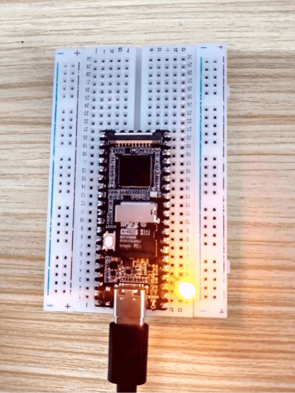
3] Test the GPIO sample provided by the official SDK:
Source code: luckluckfox-gpio-test.c
3-1] Send the test routine to the Pico development board
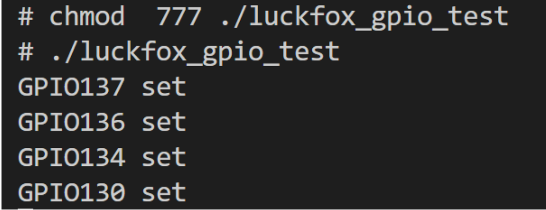
3-2] Before running the program, make sure to grant executable permissions:chmod 777 ./luckfox_gpio_test
3-3] Run luckluckfox_gpio_test:
4] Verify the luckfox_gpio_test example:
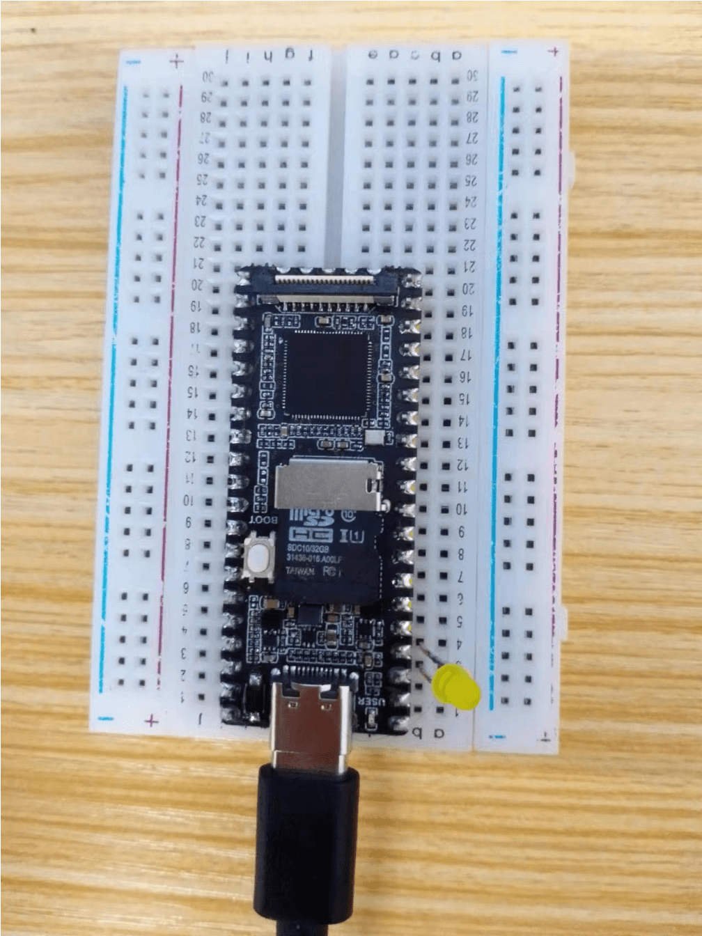
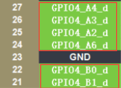
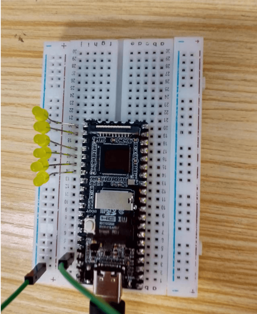
4-1] Connect the LED to the following pins using the plugin.
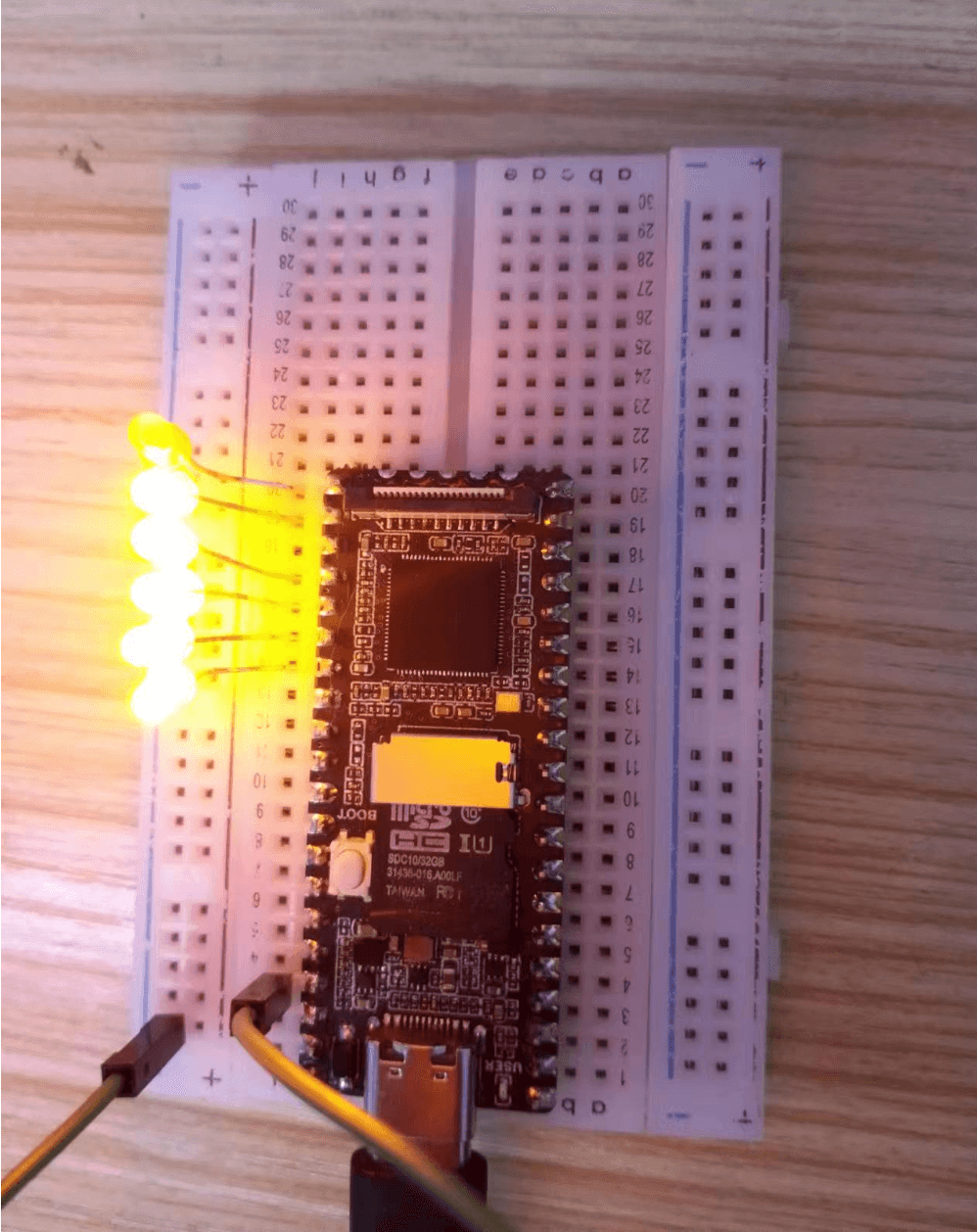
4-2] he experimental phenomenon is that the LED lights up and turns off sequentially.
】FAQ:
The number of GPIO can be calculated as follows, taking GPIO1_C7_d as an example:
GPIO1_C7_d = 1*32 + 2*8 + 7 = 55
(A=0, B=1, C=2, D=3)
Explanation of the calculation process:
In some microcontrollers or chips, pins or I/O ports are typically identified and accessed using a numbering system. This numbering system is usually composed of multiple parts, such as GPIO group, GPIO group letter, and digits.
In this example, GPIO1_C7_d is an identifier for a pin. Let’s break down the meaning of GPIO1_C7_d:
Explanation of the calculation process:
The calculation “1 * 32 + 2 * 8 + 7 = 55” is used to convert GPIO1_C7_d into a numerical identifier. Here’s how each part is calculated:
“1 * 32” represents the GPIO group number (Group) multiplied by the number of pins in each GPIO group. In this case, GPIO1 group has 32 pins.
“2 * 8” represents the index of the GPIO group letter (Group Letter) multiplied by the number of pins represented by each letter. In this device, the letter represents C, indicating it is the third letter in the group, and each letter has 8 pins.
“7” represents the number of the 7th pin (Digit).
By multiplying and adding these parts together, we get the numerical identifier of the pin GPIO1_C7_d as 55.
This numerical identifier calculation helps uniquely identify and access each pin, making it convenient for pin configuration and control in programming.
GPIO Group: In this case, it is GPIO1.
GPIO groups are used to differentiate different groups of pins. A chip may have multiple GPIO groups.
GPIO Group Letter: In this case, it is C.
GPIO group letters are used to further divide the pins within each GPIO group, typically starting from A and incrementing. (A=0, B=1, C=2, D=3)
Digit: In this case, it is 7, representing the 7th pin under the C letter in the GPIO group.
Suffix: In this case, it is the letter “d”.
Suffixes are often used to differentiate different functions or properties, such as input or output.