


- sales/support
Google Chat:---
- sales
+86-0755-88291180
- sales01
sales@spotpear.com
- sales02
dragon_manager@163.com
- support
tech-support@spotpear.com
- CEO-Complaints
zhoujie@spotpear.com
- Only Tech-Support
WhatsApp:13246739196
- Purchase/Shipping/Refund
WhatsApp:13424403025
- HOME
- >
- ARTICLES
- >
- Common Moudle
- >
- UART Module
TTL-TO-RS485-C User Guide
Overview
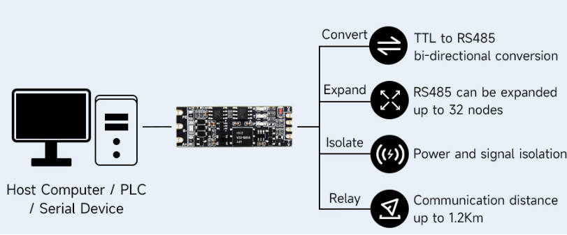
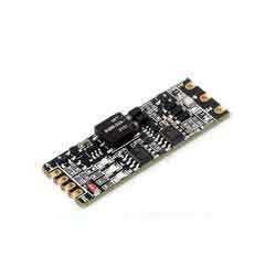
TTL TO RS485 (C) is a mini galvanic isolated TTL-to-RS485 serial converter.
Feature
- Compatible with TTL/RS485 standard, converting the TTL signal into differential RS485 signal, supports half-duplex communication.
- Compatible with 3.3V ~ 5V TTL signal level, provides over-voltage protection for power supply interface.
- Onboard unibody power supply isolation, provides stable isolated voltage and needs no extra power supply for the isolated terminal.
- Onboard unibody digital isolation, allows signal isolation, high reliability, strong anti-interference, low power consumption.
- Onboard TVS (Transient Voltage Suppressor), effectively suppresses surge voltage and transient spike voltage in the circuit, lightningproof & anti-electrostatic.
- Onboard self-recovery fuse and protection diodes, ensure the current/voltage stable outputs, provide over-current/over-voltage protection, improve shock-proof performance.
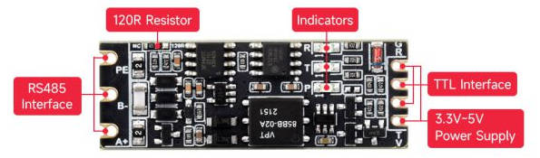
- Onboard RS485 output terminal 120R resistor, enabled via soldering.
- Black immersion gold process design, compact size, easy to integrate.
Parameters
| Model | Galvanic isolated TTL To RS485 converter | |
|---|---|---|
| Power Port | Power supply | 3.3V ~ 5V |
| Interface Protection | anti-over-discharge | |
| Device interface | Compatible with TTL / RS485 standard | |
| TTL Interface | Interface type | Screw terminal |
| Transmission distance | Less than 10m | |
| Transmission model | Point to point | |
| RS485 Interface | Interface Protection | Provide 200W lightningproof, surge-suppress and 6KV ESD protection |
| Terminal Resistance | 120R, enabled via soldering | |
| Transmission Distance | About 1200m | |
| Transmission Mode | Point-to-multipoint (up to 32 nodes, it is recommended to use repeaters for 16 nodes or more) | |
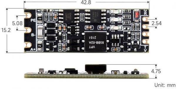
| Appearance | Dimensions | 42.8 x 15.2 x 4.75mm |
Primary Function
Convert the TTL signal into a balanced differential RS485 signal, which can be used for interface conversion and node expansion, and can also be used to extend the communication distance.
Onboard Interface
| Indicator | |
| R (RXD) | RX indicator, lights up when the TTL port receives data |
| T (TXD) | TX indicator, lights up when the TTL port sends data |
| P (PWR) | Power indicator, lights up when there is a power supply connection and voltage is detected |
| LEFT SIDE INTERFACE | RIGHT SIDE INTERFACE | ||
|---|---|---|---|
| PE | RS485 Signal Ground | GND | Ground |
| RXD | TTL Signal Receiving Pin | ||
| B- | RS485 Differential Signal Negative B- | TXD | TTL Signal Transmitting Pin |
| A+ | RS485 Differential Signal Positive A+ | VCC | Power Input DC 3.3V ~ 5V Power Supply |
Communication Connection Diagram
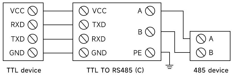
TTL convert to RS485, point to point, half-duplex communication, suitable for interface conversion
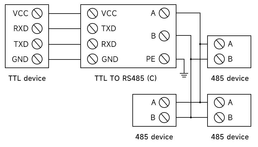
TTL convert to RS485, point-to-multipoint, half-duplex communication, suitable for expanding nodes
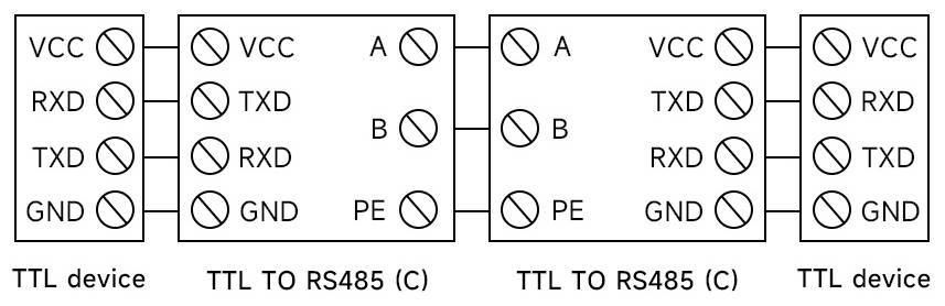
Two groups TTL To RS485 conversion, point-to-point, half-duplex communication, suitable for extending the communication distance of TTL
Dimensions
Hardware Test
Test Note
Test Environment: PC (Windows).
Accessories required for testing:
- TTL TO RS485 (C) — This product
- USB TO TTL - not included
- USB TO RS485 - not included
Test Hardware Connection
Connect the RS485 interface of TTL TO RS485 (C) to the PC through the USB to RS485 cable. Connect the TTL interface of TTL TO RS485 (B) to the TTL interface of USB TO TTL, and then connect the USB port of USB TO TTL to the same PC for the self-transmission test. The schematic diagram of the hardware connection is as follows:
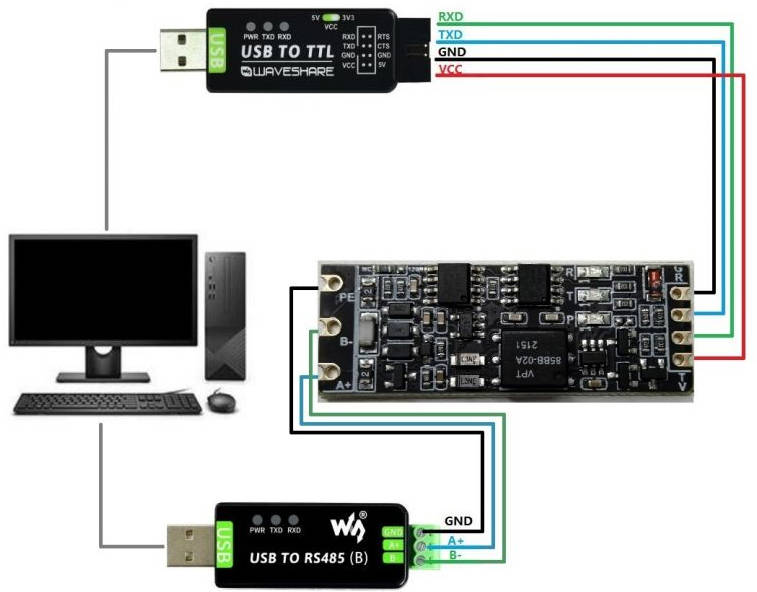
Note: The RS485 interface of this product is also equipped with 120R enable switch, the default setting is on, the user can set it according to the needs (set up to open, set down to NC), if signal isolation is required, you can connect GND to ground.
Software Operation
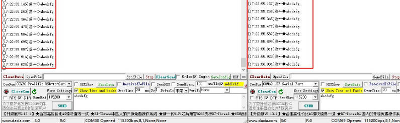
- Open two SSCOM interfaces.
- Select two corresponding COM ports.
- Select the baud rate as 115200, input the characters to be sent, select "Show Time and Packet" to view it more intuitively, and then click on "Open COM".
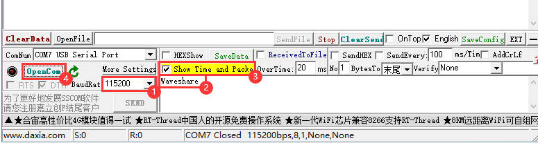
- In these two SSCOM interfaces, select Send Every 100ms, and you can see the effect.
Resource
FAQ
Question:What is the maximum communication rate of TTL to RS485 (C)?
Test within 2M baud rate can work stably.
The hardware itself does not limit the usage rate but mainly depends on the access to the TTL and RS485 devices, as well as the communication environment and communication distance and other factors.
Support
Monday-Friday (9:30-6:30) Saturday (9:30-5:30)
Mobile: +86 13434470212
Email: services01@spotpear.com
017.jpg)
018.jpg)
019.jpg)
_Spec07.jpg)
[Tutorial Navigation]
- Overview
- Feature
- Parameters
- Primary Function
- Onboard Interface
- Communication Connection Diagram
- TTL convert to RS485, point to point, half-duplex communication, suitable for interface conversion
- TTL convert to RS485, point-to-multipoint, half-duplex communication, suitable for expanding nodes
- Two groups TTL To RS485 conversion, point-to-point, half-duplex communication, suitable for extending the communication distance of TTL
- Dimensions
- Hardware Test
- Resource
- FAQ
- Support