


- sales/support
Google Chat:---
- sales
+86-0755-88291180
- sales01
sales@spotpear.com
- sales02
dragon_manager@163.com
- support
tech-support@spotpear.com
- CEO-Complaints
zhoujie@spotpear.com
- Only Tech-Support
WhatsApp:13246739196
- Purchase/Shipping/Refund
WhatsApp:13424403025
- HOME
- >
- ARTICLES
- >
- Common Moudle
- >
- Power
UPS-Module-Mini User Guide
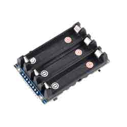
Overview
This is a mini uninterruptible power supply (UPS) module that supports simultaneous charging and discharging. It can provide a stable 5V voltage output and supports I2C communication, allowing for access to information such as battery voltage, current, power, and charging status.
Features
- Mini UPS expansion board for easy soldering or integration into mobile robots and industrial control equipment.
- I2C bus communication, monitoring the battery's voltage, current, power, and remaining capacity in real time.
- Onboard multiple function pins, provide two charging and discharging methods via pads and pin headers.
- Multiple battery protection circuits: overcharge/discharge protection, over current protection, short circuit protection, and reverse protection, along with the equalizing charge feature, more safe and stable.
- Onboard 5V regulator, up to 2.5A continuous output current.
- Onboard warning indicators, easy to check if the battery is connected correctly and the charging status.
- Comes with online development resources and a manual.
Parameters
- Output voltage: 5V
- Charging power: 5V
- Control interface: I2C
- Batteries: 350mAh 10440 Lithium Battery 3.7V (NOT included)
- Dimensions: 61 × 38mm
Hardware Description
| Pin | Function |
| IN | Power input (5V 3A) |
| OUT | UPS output (5V 2.5A) |
| GND | ground |
| UPS OFF | turn off the UPS power output when connected to the PWR pin |
| BOOT | Batteries activation (pull low for 500ms and then pull high) |
| CHARGE | Charge indication (low level indicates charging) |
| SCL | I2C clock |
| SDA | I2C data |
| PWR | UPS ON/OFF (turn off UPS power output when connected to UPS OFF pin) |
Note 1: When initially connecting the battery, pay attention to whether the WARNING LED is on. If the LED is on, it indicates that the corresponding battery is connected reversely. Charging is prohibited when the battery is connected reversely.
Note 2: When initially connecting the battery, there may be no power output. Press the BOOT button on the circuit board to activate the battery protection chip and enable power output.
Note 3: To charge the product, use the power supply provided with the product. Using other power chargers may result in unstable power output with excessive ripple, which can damage the product.
Note 4: If the insulation pad on the positive electrode of the battery is removed or damaged, it is recommended not to continue using it as it can easily lead to a short circuit and fire. When removing the battery, avoid using a screwdriver to pry the positive electrode, as it can easily cause a short circuit. Instead, you should focus on prying the negative electrode of the battery.
SAFETY CAUTIONS
- Li-ion and Li-po batteries are quite unstable. They may cause fire, personal injury, or property damage if they're not properly recharged or used.
- Do not reversely connect the polarities when recharging or discharging the battery. Do not use an inferior charger/charging panel to recharge the battery.
- Do not mix use old batteries with new ones, avoid using batteries of different brands.
- When buying a Lithium battery, should always make sure the battery specification is compatible with the expansion board. Choose batteries from the formal manufacturer, and ensure the batteries will work stably and safely by aging test.
- Lithium batteries have limited cycle life, they will also deteriorate as time goes by. Should be replaced with new ones when the batteries reach their max cycle life, or work over two years, whichever comes first.
- Should be placed carefully and properly, keep it away from inflammable and explosive articles, away from children, and avoid any safety accident caused by careless storage.
How to Use the Demo
Working with Raspberry Pi
Hardware Connection
Note: Here it only communicates with the host, if you want to charge and discharge, you need to connect IN and OUT.
| UPS Module Pin | Raspberry Pi (BCM) |
| GND | GND |
| SDA | 2 |
| SCL | 3 |
| CHARGE | 4 |
Demo Usage
Enable I2C Interface
- Open the Raspberry Pi terminal, and run the following commands to enter the configuration interface:
sudo raspi-config
Select Interfacing Options -> I2C -> Yes to enable the I2C interface
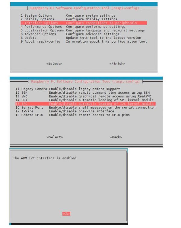
And then reboot the Raspberry Pi:
sudo reboot
Please make sure that the I2C is not occupied by other devices, you can check in the middle of /boot/config.txt.
Install Libraries
BCM2835
#Open the Raspberry Pi terminal and run the following commands
wget http://www.airspayce.com/mikem/bcm2835/bcm2835-1.71.tar.gz
tar zxvf bcm2835-1.71.tar.gz
cd bcm2835-1.71/
sudo ./configure && sudo make && sudo make check && sudo make install
# For more, you can refer to the official website at http://www.airspayce.com/mikem/bcm2835/
WiringPi
git clone https://github.com/WiringPi/WiringPi
cd WiringPi
./build
gpio -v
# Run gpio -v and version 2.70 will appear, if it does not appear it means there is an installation error
Python
#python2
sudo apt-get update
sudo apt-get install python-pip
sudo pip install RPi.GPIO
sudo pip install smbus
#python3
sudo apt-get update
sudo apt-get install python3-pip
sudo pip3 install RPi.GPIO
sudo pip3 install smbus
Download the Test Demo
Open the Raspberry Pi terminal and run the following commands:
sudo apt install unzip -y
cd ~
sudo wget https://files.waveshare.com/upload/5/58/UPS_Module_Mini_Code.zip
sudo unzip UPS_Module_Mini_Code.zip
cd UPS_Module_Mini_Code/Raspberrypi/
Run the Test Demo
Please run the following commands in the Raspberry Pi. Otherwise, you can not find the directory if it is not in the index.
C
- Recompile and it may take a few seconds to compile:
cd ~/UPS_Module_Mini_Code/Raspberrypi/c/
sudo make clean
sudo make -j
sudo ./ups_module
Python
d ~/UPS_Module_Mini_Code/Raspberrypi/python/
sudo python UPS_Module_Mini.py
- Run the demo corresponding to the screen you used, and the demo supports python2/3.
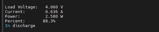
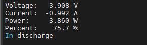
Running Effect
- From top to bottom, the parameters are battery voltage, battery current, battery power, and whether it is charging or not.
- In charge: charging.
- In discharge: being discharged.
- The chart below shows the actual value, not the maximum value.
Discharge
Charge
C Library Selection
- We use our own IO library by default: USE_DEV_LIB.
- This can be changed by modifying the Makefile with the following command:
# USELIB = USE_BCM2835_LIB
# USELIB = USE_WIRINGPI_LIB
USELIB = USE_DEV_LIB
- Choose one of the three, and you need to remove the corresponding comment and add the comments to the others. Otherwise, it will runs the last one.
- For example, if you need to use the wiringpi library for compilation, set it like this:
# USELIB = USE_BCM2835_LIB
USELIB = USE_WIRINGPI_LIB
# USELIB = USE_DEV_LIB
Note: You need to reboot Raspberry Pi after using the BCM2835 library, otherwise you can't use Python and other libraries of C programs.
Raspberry Pi Pico
Hardware Connection
Note: Here it only communicates with the host, if you want to charge and discharge, you need to connect IN and OUT.
| UPS Module Pin | Raspberry Pi Pico |
| GND | GND |
| SDA | 8 |
| SCL | 9 |
| CHARGE | 7 |
C/C++ Development Environment Installation
- Before using the demos and tutorials, you need to set up the development environment and learn the basic usage of the project:
MicroPython Development Environment Installation
- Download Thonny Python IDE (Windows V3.3.3) and install it by steps.
- *After installing, please configure the language and the environment for the first time. Note that we should choose the Raspberry Pi option in the board environment.
- Configure the Micrpython environment and select the Pico port.
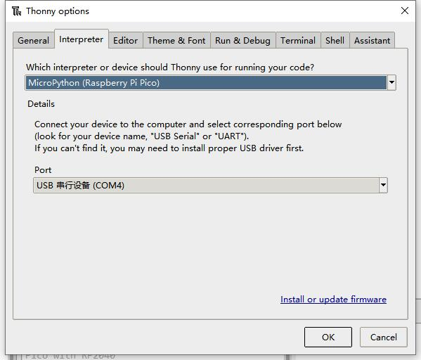
- First connect the Raspberry Pi Pico to the computer, left-click on the configuration environment option in the lower right corner of Thonny --> select configure an interpreter.
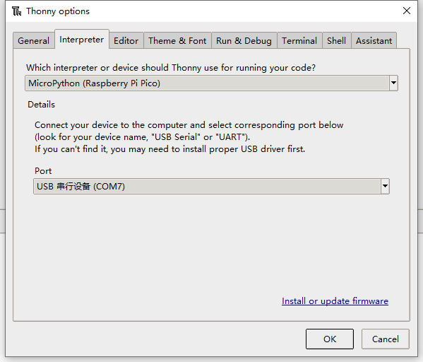
- In the pop-up window bar, select MicroPython (Raspberry Pi Pico), and select the corresponding port.
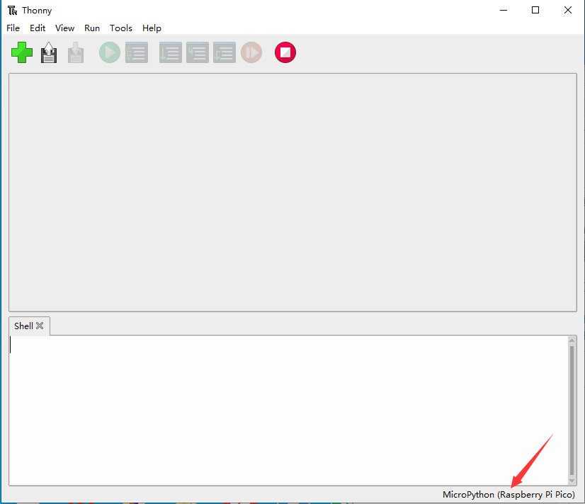
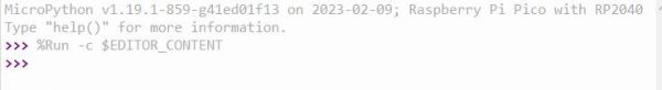
- Click OK to return to the main interface of Thonny, download the firmware library to Pico, and then click the stop button to display the currently used environment in the Shell window.
- Pico download firmware library method in Windows: Press and hold the BOOT button and connect to the computer, release the BOOT button, and a removable disk will appear on the computer and copy the firmware library into it.
In the Raspberry Pi
- Open the Raspberry Pi terminal and execute:
sudo apt install unzip -y
cd ~
sudo wget https://files.waveshare.com/upload/5/58/UPS_Module_Mini_Code.zip
unzip UPS_Module_Mini_Code.zip
cd ~/UPS_Module_Mini_Code
cd Pico/c/build/
How to Use the Demo
C
- Please operates the following tutorial on Raspberry Pi, but due to the multi-platform and portable nature of CMake, it can also be compiled successfully on PC, but the operation is slightly different and requires your own judgment.
- To perform the compilation, make sure that in the c directory:
cd ~/UPS_Module_Mini_Code/Pico/c/
Create and enter the build directory, and add the SDK: ../../pico-sdk is the directory of your SDK. There is a build in our sample application, just enter it directly.
cd build
export PICO_SDK_PATH=../../pico-sdk
(Note: Be sure to write the right path to your own SDK)
Execute cmake to automatically generate the Makefile file:
cmake ..
Execute make to generate the executable file, you may wait for a long time as it is the first time to be compiled.
make -j9
After compiling, uf2 file will generate. Press the button on the Pico board, Pico can connect to the USB port of the Raspberry Pi via a Micro USB cable, and then release the buttons. After connecting, Raspberry Pi will automatically identify a movable disk (RPI-RP2), and copy main.uf2 in the build file to the recognizable movable disk (RPI-RP2).
cp main.uf2 /media/pi/RPI-RP2/
Python
- 1. On the Raspberry Pi, copy ~/UPS_Module_Mini_Code/Pico/python/rp2-pico-20230329-unstable-v1.19.1-994-ga4672149b.uf2 to Pico.
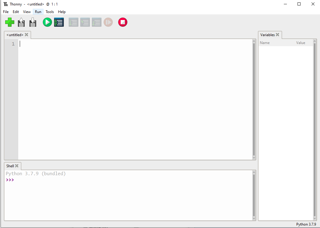
- 2. Open Thonny IDE on the Raspberry Pi (click Raspberry Pi logo -> Programming -> Thonny Python IDE), and you can check the version information in Help -> About Thonny.
To ensure your version that your version includes the package supported Pico, you can click Tools -> Options... -> Interpreter, and choose MicroPython (Raspberry Pi Pico and ttyACM0 port). As shown below: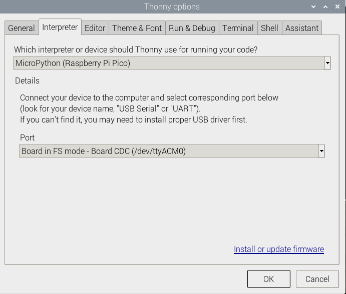
If your current Thonny version has no package supporting Pico, you can enter the following commands to update Thonny IDE.
sudo apt upgrade thonny
3. Click File -> Open... -> ~/UPS_Module_Mini_Code/Pico/python/UPS_Module_Mini.py, and then run the script.
Windows
- Click here to download, decompress it to the Pico file folder.
C
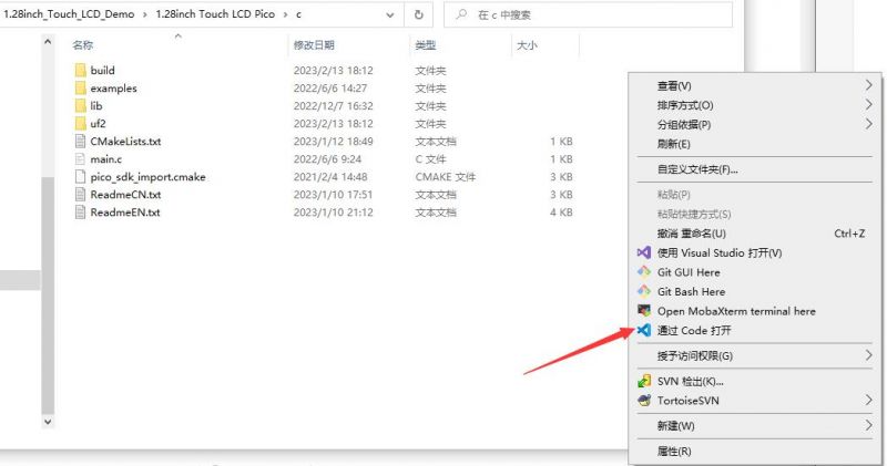
- After entering Pico\c, you can open the project with vs code.
- Choose the Compiler.
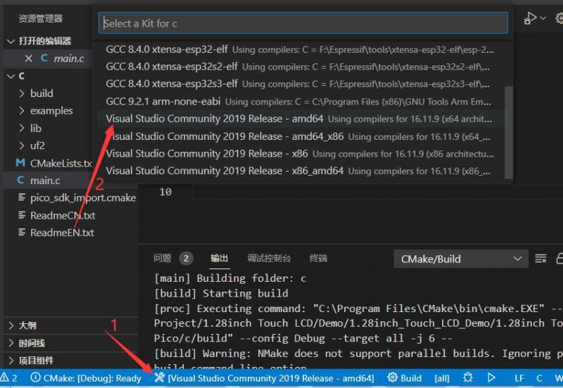
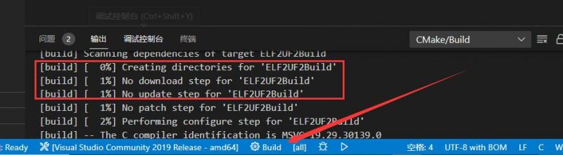
- Start to compile.
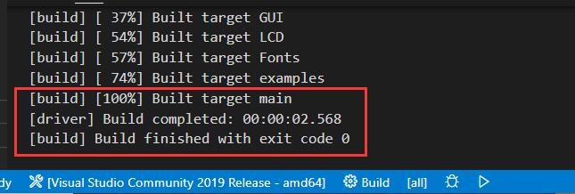
- Finish.
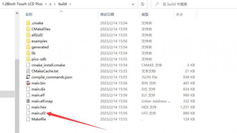
- Copy the UPS_Module_Mini.uf2 in build to Pico, and then it can automatically run the demo.
Python
- Press the BOOTSET button on the Pico and connect the Pico to the USB port of the computer with a Micro USB cable. Release the button when the computer identifies a movable disk (RPI-RP2).
- Copy rp2-pico-20230329-unstable-v1.19.1-994-ga4672149b.uf2 file in the python directory to the recognizable movable disk(RPI-RP2).
- Open Thonny IDE (Note: please use the latest version of Thonny, otherwise there is no Pico supporting package. Currently, the newest version in Windows is v3.3.3.)
- Click Tool -> Setting -> Explainer. select the Pico and the corresponding port as shown below:
- File -> Open -> UPS_Module_Mini.py, click to run, the effect is shown as below.
We provide a simple demo for you...
Running Effect
- Information content to view the Raspberry Pi operation effect introduction.
C
- You need to open Pico's virtual serial port to view information through the serial debugging assistant.
Python
- After running the demo, you can view the information in the shell.
MicroPython (For Raspberry Pi Pico)
Working with STM32
Hardware Connection
Note: Here it only communicates with the host, if you want to charge and discharge, you need to connect IN and OUT.
| Module Pin | STM32F103RB |
| GND | GND |
| SDA | PB9 |
| SCL | PB8 |
| CHARGE | PB5 |
Download Example
The demos are developed based on the HAL library.
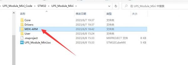
Click to download the demo, unzip it, and open UPS_Module_Mini_Code\STM32\UPS_Module_Mini\MDK-ARM directory of UPS_Module_Mini.uvprojx to see the demo.
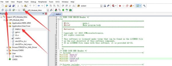
Open main.c, you can see the demo, and then recompile to download.
Running Effect
- Need to open the STM32's virtual serial port to view the information through the serial debug assistant.
- Information content to view the operation of the Raspberry Pi effect introduction.
Working with Arduino
Note: The demos are tested on Arduino Uno, if you need to use other models of Arduino you need to make sure that the pins are connected correctly.
Arduino IDE Installation
Hardware Connection
Note: Here only communicate with the host, if you want to charge and discharge, you need to connect IN and OUT.
| UPS Module Pin | Arduino uno |
| GND | GND |
| SDA | SDA |
| SCL | SCL |
| CHARGE | 4 |
Running the Demo
Click to download the demo, and unzip it. Note the demo is in UPS_Module_Mini_Code\Arduino\UPS_Module_Mini.
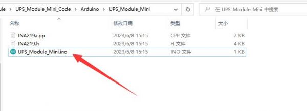
Install the Arduino IDE, and then run the UPS_Module_Mini.ino file.
Open the program, and select the development board as Arduino UNO.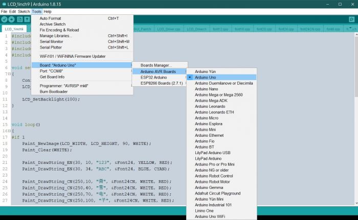
Select the corresponding port.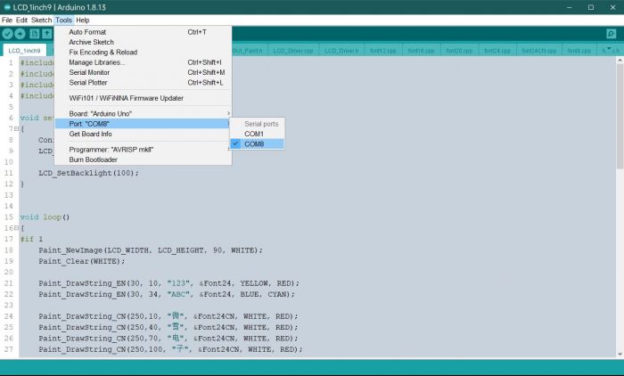
And then click to compile and download.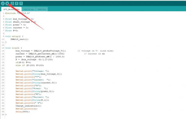
Running Effect
- You need to open the virtual serial port of Arduino UNO to view the information through the serial debugging assistant.
- Information content to view the operation of the Raspberry Pi effect introduction.
Resource
Document
Demo
Related Resource
FAQ
Support
Monday-Friday (9:30-6:30) Saturday (9:30-5:30)
Email: services01@spotpear.com
Mini Uninterruptible Power Supply module Supports charging And Power output at the same time 5V 2.5A
[Tutorial Navigation]
- Overview
- Features
- Parameters
- Hardware Description
- How to Use the Demo
- Working with Raspberry Pi
- Hardware Connection
- Demo Usage
- Running Effect
- C Library Selection
- Raspberry Pi Pico
- Hardware Connection
- C/C++ Development Environment Installation
- MicroPython Development Environment Installation
- In the Raspberry Pi
- Windows
- Working with STM32
- Working with Arduino
- Resource
- FAQ
- Support