


- sales/support
Google Chat:---
- sales
+86-0755-88291180
- sales01
sales@spotpear.com
- sales02
dragon_manager@163.com
- support
tech-support@spotpear.com
- CEO-Complaints
zhoujie@spotpear.com
- Only Tech-Support
WhatsApp:13246739196
- Purchase/Shipping/Refund
WhatsApp:13424403025
- HOME
- >
- ARTICLES
- >
- Common Moudle
- >
- ESP
ESP32-S3-LCD-3.16 User Guide
Introduction
Introduction
This product uses the ESP32-S3R8 chip, supports 2.4GHz Wi-Fi and BLE 5 Bluetooth functions, and has built-in large capacity Flash and PSRAM. It is equipped with a 3.16inch HD LCD display, and can smoothly run GUI programs such as LVGL. It has integrated RTC, IMU, TF card slot, and lithium battery charging function, with rich peripheral resources. It also reserves USB, UART and I2C ports, offering flexible expandability. It is an ideal choice for quickly developing HMI applications based on ESP32-S3.
Features
- Equipped with high-performance Xtensa 32-bit LX7 dual-core processor, up to 240MHz main frequency
- Supports 2.4GHz Wi-Fi and Bluetooth 5 (LE), onboard internal antenna, with solder joints reserved for external antenna
- Built-in 512KB SRAM and 384KB ROM, with onboard 16MB Flash and 8MB PSRAM
- Onboard 3.16inch LCD display, 320×820 resolution, 64K color, RGB565 communication interface
- Onboard QMI8658 6-axis IMU (3-axis accelerometer and 3-axis gyroscope) for detecting motion gesture, step counting, etc.
- Built-in PCF85063 RTC chip, with a reserved SH1.0 battery slot for easy implementation of RTC functionality
- Use the toggle switch to control the power on and off, providing higher controllability
- Onboard RST and BOOT side buttons, BOOT supports custom button functions, making development and use more flexible
- Onboard 3.7V MX1.25 lithium battery recharge/discharge header
- Built-in TF card slot, supports external TF card storage for images or files
- Bring out UART, I2C SH1.0 4PIN interface and USB MX1.25 4PIN interface
- Onboard USB Type-C port for power supply, firmware downloading and debugging, making development more convenient
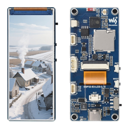
Onboard Resources
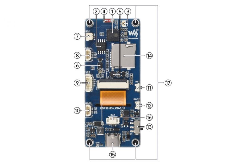
1. ESP32-S3R8 3. IPEX1 external antenna interface (resoldering required) 4. Onboard SMD antenna 5. QMI8658 11. RST button | 12. BOOT button |
Interfaces
For more details, please refer to the Schematic Diagram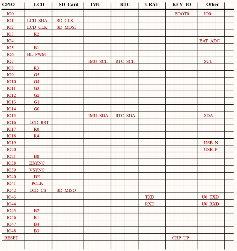
Dimensions
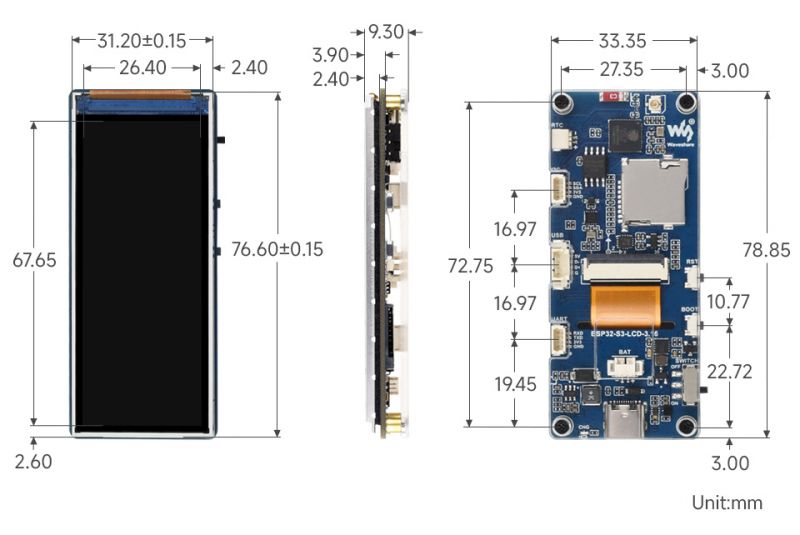
LCD Screen Parameters

Usage Instructions
ESP32-S3-LCD-3.16 currently provides two development tools and frameworks, Arduino IDE and ESP-IDF, providing flexible development options, you can choose the right development tool according to your project needs and personal habits.
Development Tool
| Arduino IDEArduino IDE is an open source electronic prototyping platform, convenient and flexible, easy to get started. After a simple learning, you can start to develop quickly. At the same time, Arduino has a large global user community, providing an abundance of open source code, project examples and tutorials, as well as rich library resources, encapsulating complex functions, allowing developers to quickly implement various functions. |
| ESP-IDFESP-IDF, or full name Espressif IDE, is a professional development framework introduced by Espressif Technology for the ESP series chips. It is developed using the C language, including a compiler, debugger, and flashing tool, etc., and can be developed via the command lines or through an integrated development environment (such as Visual Studio Code with the Espressif IDF plugin). The plugin offers features such as code navigation, project management, and debugging, etc. |
Each of these two development approaches has its own advantages, and developers can choose according to their needs and skill levels. Arduino are suitable for beginners and non-professionals because they are easy to learn and quick to get started. ESP-IDF is a better choice for developers with a professional background or high performance requirements, as it provides more advanced development tools and greater control capabilities for the development of complex projects.
Components Preparation
- ESP32-S3-LCD-3.16 x1
- TF card (FAT32 format) x1
- USB cable (Type-A male to Type-C male) x1
Working with Arduino
This chapter introduces setting up the Arduino environment, including the Arduino IDE, management of ESP32 boards, installation of related libraries, program compilation and downloading, as well as testing demos. It aims to help users master the development board and facilitate secondary development.

Environment Setup
Download and Install Arduino IDE
- Click to visit the Arduino official website, select the corresponding system and system bit to download
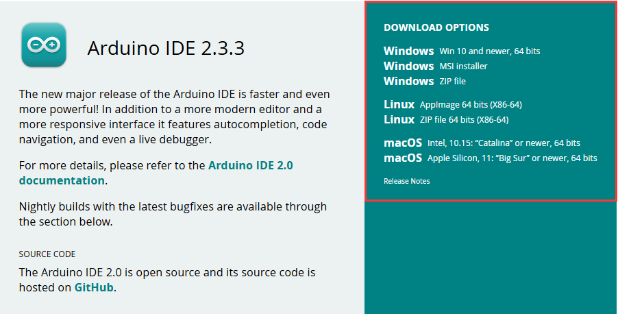
- Run the installer and install all by default
Install ESP32 Development Board
- Before using ESP32-related motherboards with the Arduino IDE, you must first install the software package for the esp32 by Espressif Systems development board
- According to board installation requirement, it is generally recommended to use Install Online. If online installation fails, use Install Offline.
- For the installation tutorial, please refer to Arduino board manager tutorial
| Board name | Board installation requirement | Version number requirement |
|---|---|---|
| esp32 by Espressif Systems | "Install Offline" / "Install Online" | ≥3.1.0 |
Install Library
- When installing Arduino libraries, there are usually two ways to choose from: Install online and Install offline. If the library installation requires offline installation, you must use the provided library file
For most libraries, users can easily search and install them through the online library manager of the Arduino software. However, some open-source libraries or custom libraries are not synchronized to the Arduino Library Manager, so they cannot be acquired through online searches. In this case, users can only manually install these libraries offline. - For library installation tutorial, please refer to Arduino library manager tutorial
- ESP32-S3-LCD-3.16 library file path:
..\ESP32-S3-LCD-3.16-Demo\Arduino\libraries
| Library Name | Description | Version | Library Installation Requirement |
|---|---|---|---|
| LVGL | Graphical library | v8.3.11/v9.3.0 | "Install Offline" |
| SensorLib | Sensor control library | v0.3.1 | "Install Online" or "Install Offline" |
Run the First Arduino Demo
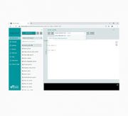
New Project
- Run the Arduino IDE and select
File->New Sketch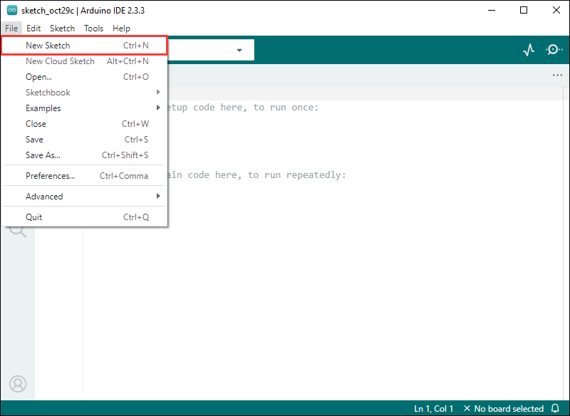
- Enter the code:
void setup() {
  // put your setup code here, to run once:
  Serial.begin(115200);
}

void loop() {
  // put your main code here, to run repeatedly:
  Serial.println("Hello, World!");
  delay(2000);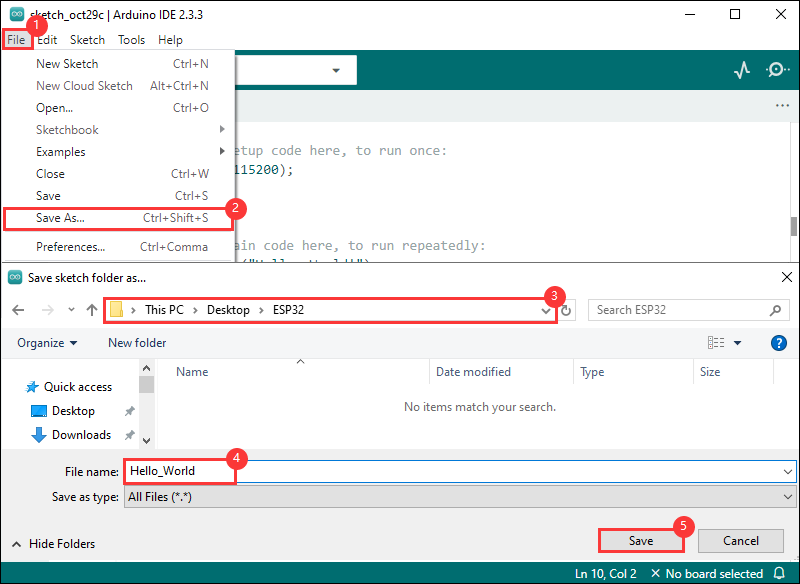
}- Save the project and select
File->Save As.... In the pop-up menu, select the path to save the project, and enter a project name, such as Hello_World, clickSave
Compile and Flash Demos
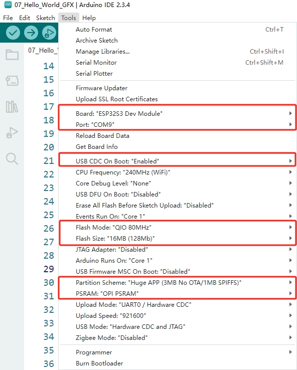
- Select the corresponding development board, take the ESP32S3 motherboard as an example:
①. Click to select the dropdown menu option Select Other Board and Port;
②. Search for the required development board model esp32s3 dev module and select;
③. Select COM Port;
④. Save the selection.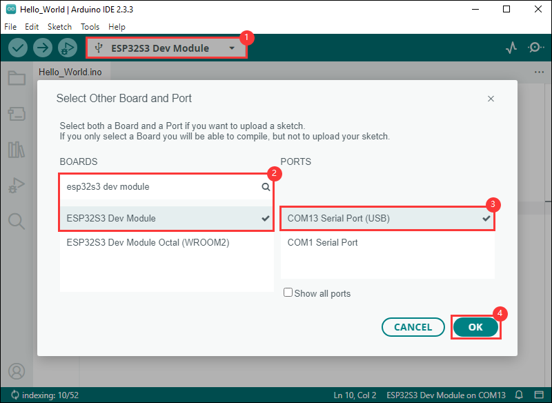
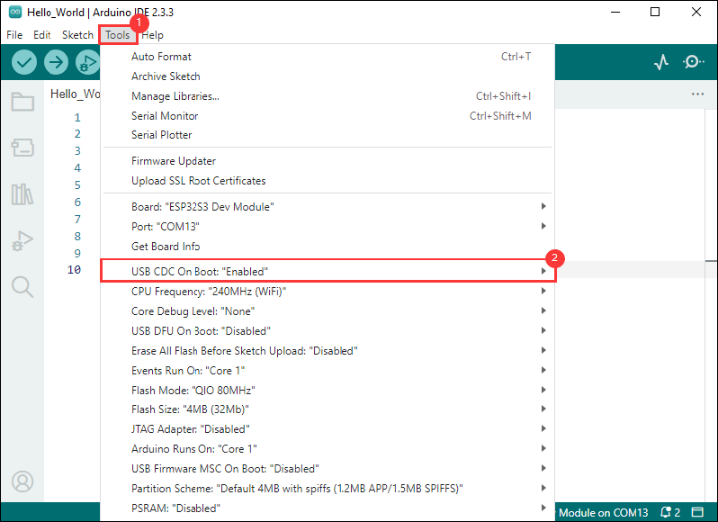
- If the ESP32S3 mainboard only has a USB port, you need to enable USB CDC, as shown in the following diagram:
- Compile and upload the program:
①. Compile the program; ②. Compile and download the program; ③. Download successful.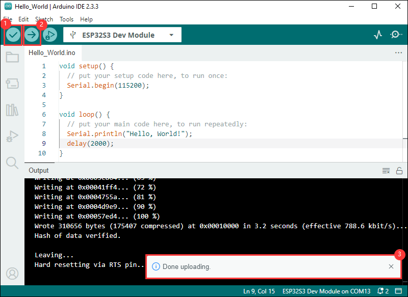
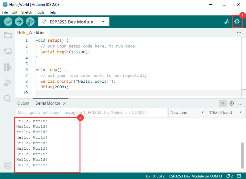
- Open the Serial Monitor window, and the demo will print "Hello World!" every 2 seconds, and the operation is as follows:
Demo

| Demo | Basic Description | Dependency Library |
|---|---|---|
| 01_ADC_Test | Read the current voltage value of the system | - |
| 02_I2C_PCF85063 | Print the real time of the RTC chip | SensorLib |
| 03_I2C_QMI8658 | Print the raw data from IMU | SensorLib |
| 04_SD_Card | Load and display the information of the TF card | - |
| 05_WIFI_AP | Set to AP mode to obtain the IP address of the access device | - |
| 06_WIFI_STA | Set to STA mode to connect to WiFi and obtain an IP address | - |
| 07_LVGL_V8_Test | LVGLV8 demo | LVGL V8.3.11 |
| 08_LVGL_V9_Test | LVGLV9 demo | LVGL V9.3.0 |
Arduino Project Parameter Setting
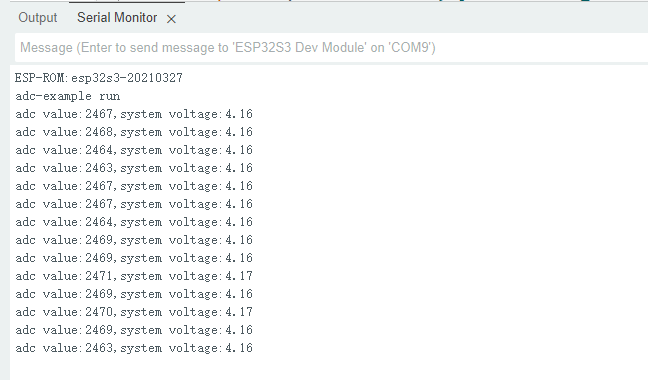
01_ADC_Test
Demo description
- The analog voltage connected through the GPIO is converted to digital by the ADC, and then the actual lithium battery voltage is calculated and printed to the terminal.
Hardware connection
- Connect the board to the computer using a USB cable
Code analysis
- adc_bsp_init(void) : Initializes ADC1, including creating an ADC one-time trigger unit and configuring channel 3 for ADC1.
- adc_get_value(float *value,int *data) : Reads the value of ADC1 channel 3 and calculates the corresponding voltage value based on the reference voltage and resolution, stores it at the position where the incoming pointer points to, and stores 0 if the read fails.
- adc_example(void* parameter): Initialize ADC1 and then create an ADC task that reads the ADC value every 1 second and calculates the system's voltage based on the raw ADC value.
Result demonstration
- The program compilation download is complete, and opening the serial port monitor will show the printed ADC values and voltage, as shown in the following figure:
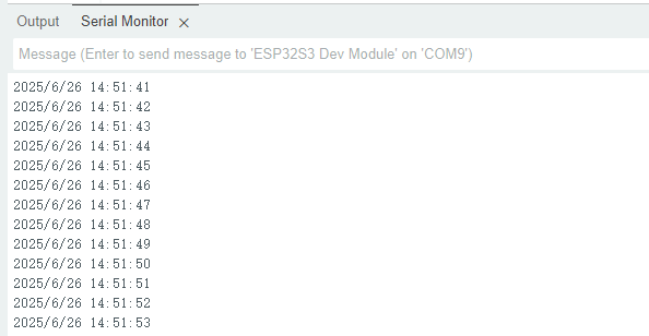
02_I2C_PCF85063
Demo description
- Through the I2C protocol, initialize the PCF85063 chip, set the time, and then periodically read the time and print it to the terminal
Hardware connection
- Connect the board to the computer using a USB cable
Code analysis
- void i2c_rtc_loop_task(void *arg) : Create an RTC task to implement RTC functionality, read the clock of the RTC chip every 1 seconds and then output it to the terminal
Result demonstration
- Open the serial port monitoring, you can see the RTC time of the printout, as shown in the figure below:
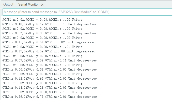
03_I2C_QMI8658
Demo description
- Through I2C protocol, initialize the QMI8658 chip, then read the corresponding attitude information every 200 milliseconds and print it to the terminal.
Hardware connection
- Connect the board to the computer using a USB cable
Code analysis
- void i2c_qmi_loop_task(void *arg) : Create a QMI task to obtain attitude information. In the task, read and print the accelerometer and gyroscope data, and output the obtained results to the serial port console at an interval of 200 milliseconds.
Result demonstration
- Open the serial port monitoring, and you can see the original data output from the IMU (Euler angles need to be converted by yourself), as shown in the following figure:
04_SD_Card
Demo description
- Drive the TF card through SDMMC, and print the TF card information to the terminal after successfully mounting.
Hardware connection
- Install TF card in FatFs format on the board before powering on
Code analysis
- sdcard_init(void) : Initialize the TF card using the 4-wire SDMMC method.
- loop(): To test the read and write function of the TF card, you need to uncomment the
#define sdcard_write_Testmacro definition.
//#define sdcard_write_TestResult demonstration
- Click on the serial port monitoring device, you can see the information of the output TF card, practical_size is the actual capacity of the TF card, as shown in the figure below:
05_WIFI_AP
Demo description
- This demo can set the development board as a hotspot, allowing phones or other devices in STA mode to connect to the development board.
Hardware connection
- Connect the board to the computer using a USB cable
Code analysis
- In the file
05_WIFI_AP.ino, findssidandpassword, then a phone or other device in STA mode can connect to the development board using these ssid and password.
const char *ssid = "ESP32_AP";
const char *password = "12345678";
Result demonstration
After flashing the program, open the serial terminal, if the device is successfully connected to the hotspot, the MAC address of the device will be output, as shown in the figure: 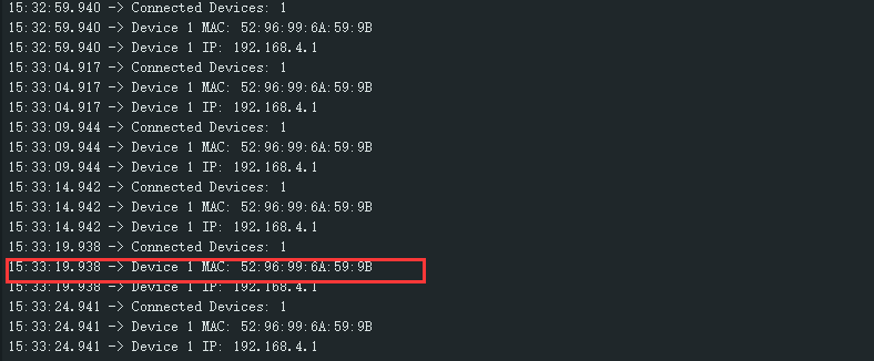
06_WIFI_STA
Demo description
- This example can configure the development board as a STA device to connect to the router and access the system network.
Hardware connection
- Connect the board to the computer using a USB cable
Code analysis
- In the file
05_WIFI_STA.ino, findssidandpassword, then modify them to the SSID and Password of the available router in your current environment.
const char *ssid = "you_ssid";
const char *password = "you_password";
Result demonstration
After flashing the program, open the serial terminal, if the device is successfully connected to the hotspot, the IP address obtained will be output, as shown in the figure: 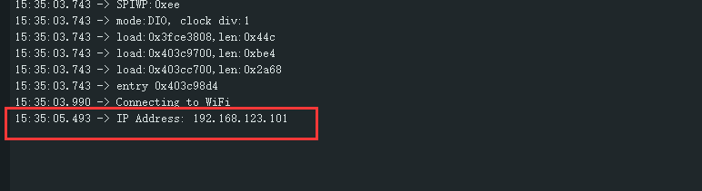
07_LVGL_V8_Test
Demo description
- Implement some multi-functional GUI interfaces on the screen by porting LVGL V8.
Hardware connection
- Connect the board to the computer using a USB cable
Code analysis
- If you need to rotate the display by 90 degrees, you can find the macro definition of
#define EXAMPLE_Rotate_90in the user_config.h file, and uncomment it. - If backlight testing is needed, you can find the macro definition of
#define Backlight_Testingin the user_config.h file, and uncomment it.
//#define Backlight_Testing
//#define EXAMPLE_Rotate_90
Result demonstration
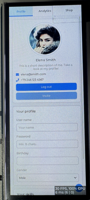
- After the demo is flashed, the running result of the device is as follows:
08_LVGL_V9_Test
Demo description
- Implement some multi-functional GUI interfaces on the screen by porting LVGL V9.
Hardware connection
- Connect the board to the computer using a USB cable
Code analysis
- If you need to rotate the display by 90 degrees, you can find the macro definition of
#define EXAMPLE_Rotate_90in the user_config.h file, and uncomment it. - If backlight testing is needed, you can find the macro definition of
#define Backlight_Testingin the user_config.h file, and uncomment it.
//#define Backlight_Testing
//#define EXAMPLE_Rotate_90
Result demonstration
- After the demo is flashed, the running result of the device is as follows:

Working with ESP-IDF
This chapter introduces setting up the ESP-IDF environment setup, including the installation of Visual Studio and the Espressif IDF plugin, program compilation, downloading, and testing of demos, to assist users in mastering the development board and facilitating secondary development. 
Environment Setup
Download and Install Visual Studio
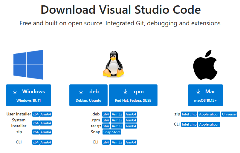
- Open the download page of VScode official website, choose the corresponding system and system bit to download
- After running the installation package, the rest can be installed by default, but here for the subsequent experience, it is recommended to check boxes 1, 2, and 3
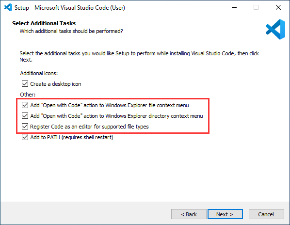
- After the first two items are enabled, you can open VSCode directly by right-clicking files or directories, which can improve the subsequent user experience.
- After the third item is enabled, you can select VSCode directly when you choose how to open it
Install Espressif IDF Plugin
- It is generally recommended to use Install Online. If online installation fails due to network factor, use Install OIffline.
- For more information about how to install the Espressif IDF plugin, see Install Espressif IDF Plugin
Run the First ESP-IDF Demo
New Project
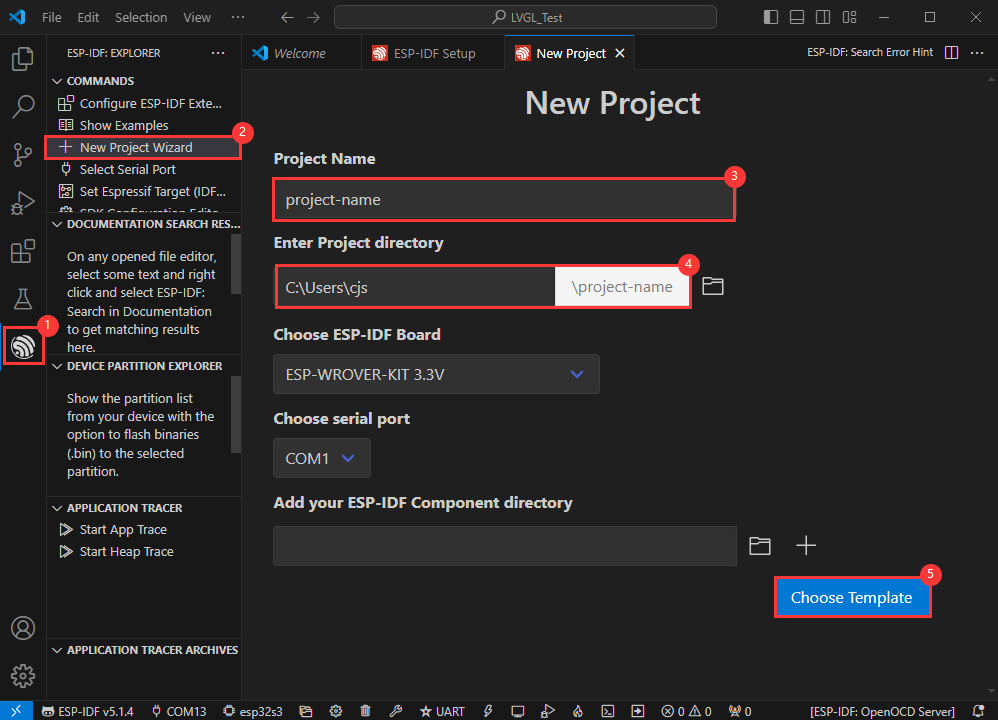
Create Demo
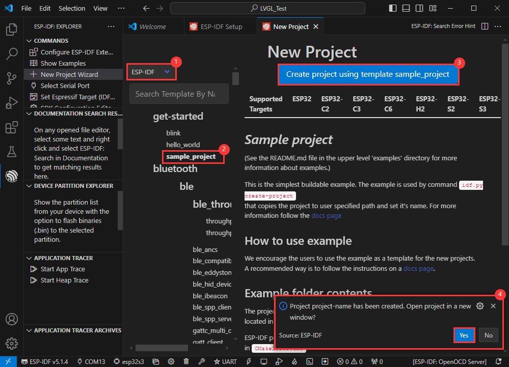
- Using the shortcut F1, enter esp-idf:show examples projects
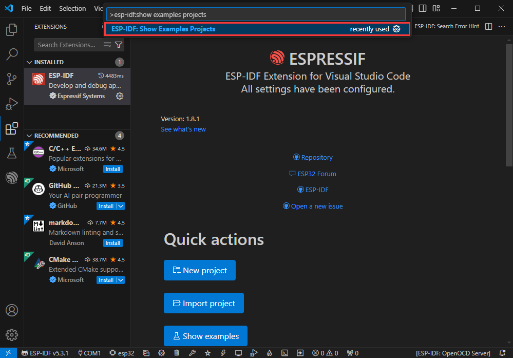
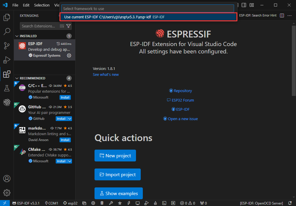
- Select your current IDF version
- Take the Hello world demo as an example
①Select the corresponding demo
②Its readme will state what chip the demo applies to (how to use the demo and the file structure are described below, omitted here)
③Click to create the demo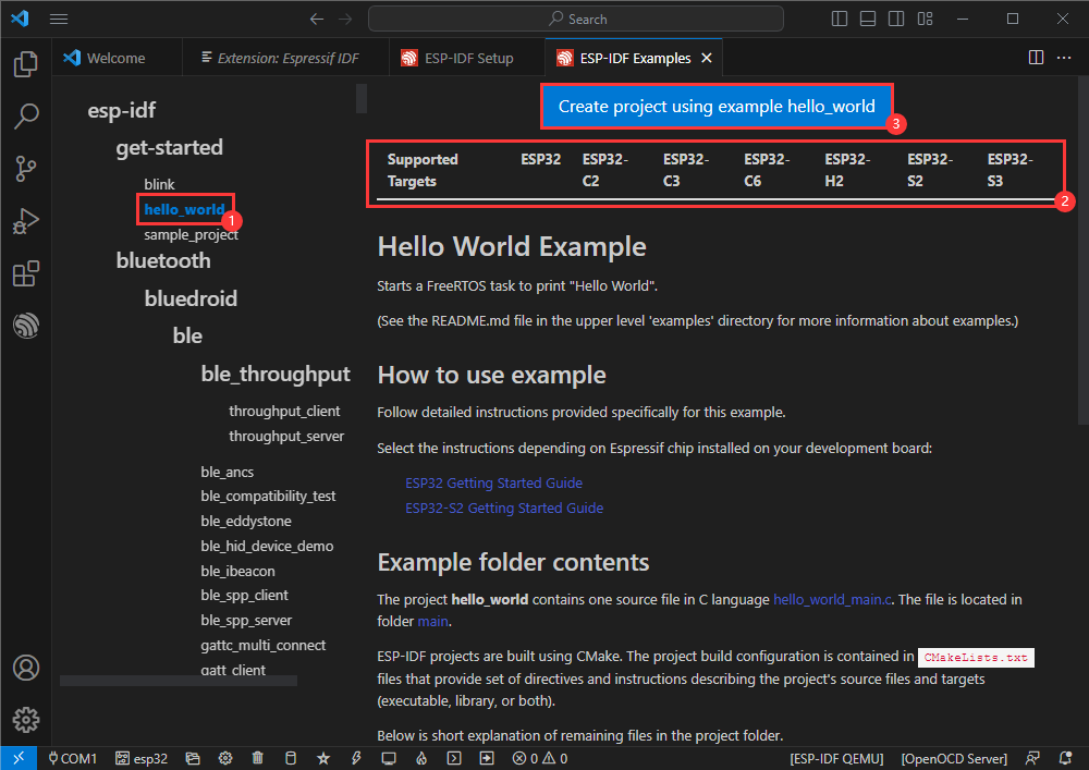
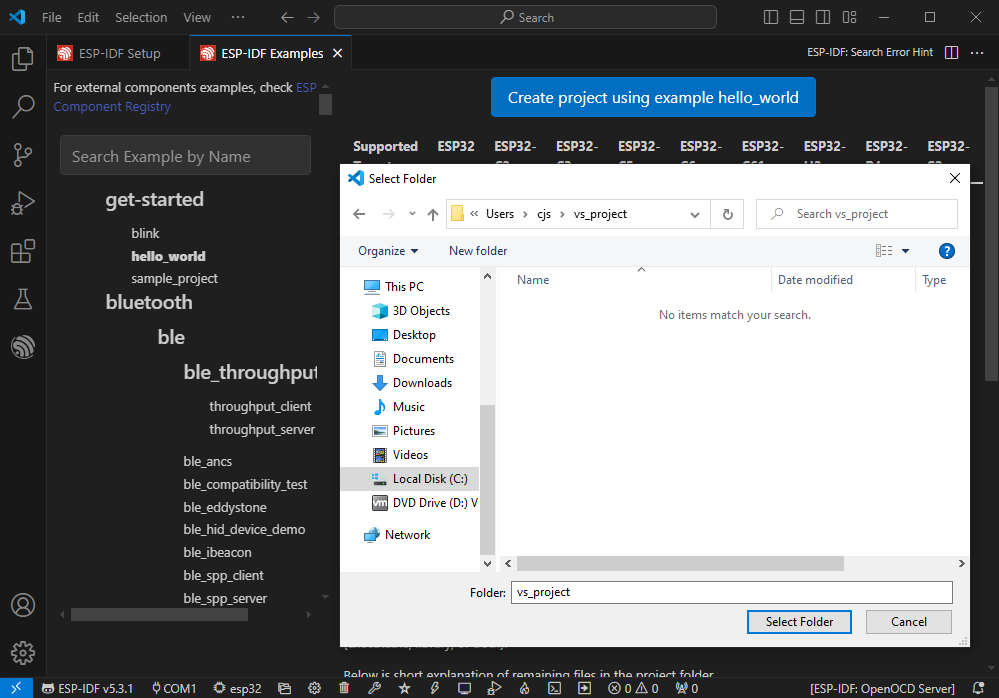
- Select the path to save the demo, and require that the demos cannot use folders with the same name
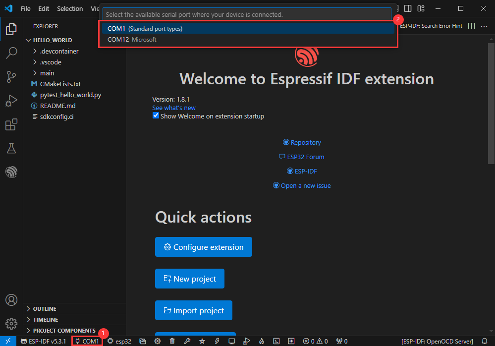
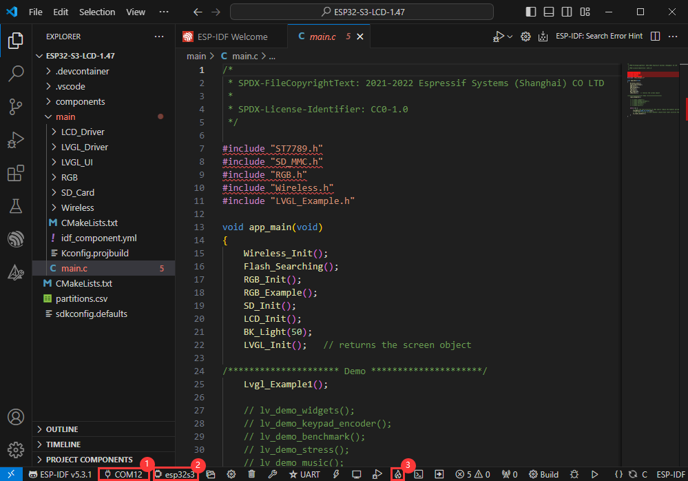
Modify COM Port
- The corresponding COM ports are shown here, click to modify them
- Please select the COM ports according to your device (You can view it from the device manager)
- In case of a download failure, please press the Reset button for more than 1 second or enter download mode, and wait for the PC to recognize the device again before downloading once more
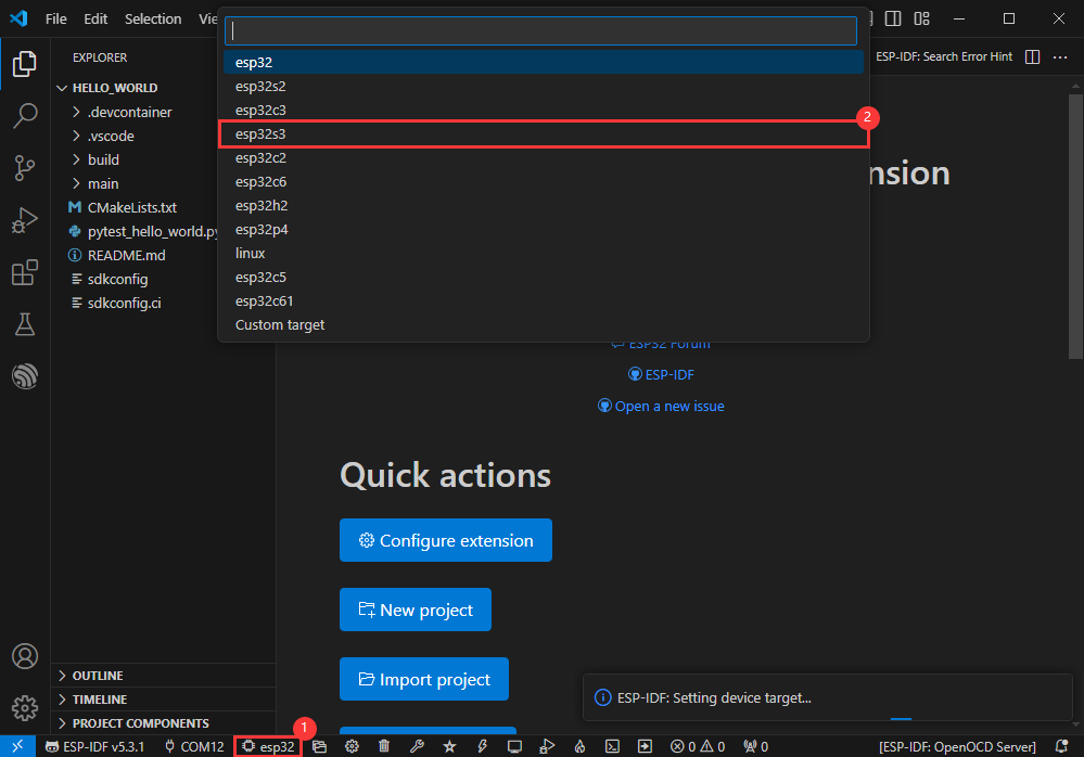
Modify Driver Object
- Select the object we need to drive, which is our main chip ESP32S3
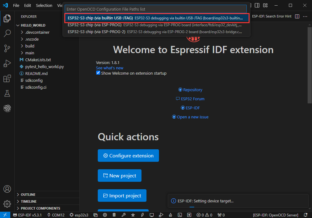
- Choose the openocd path, it doesn't affect us here, so let's just choose one
Other Status Bar Functions
①.ESP-IDF Development Environment Version Manager, when our project requires differentiation of development environment versions, it can be managed by installing different versions of ESP-IDF. When the project uses a specific version, it can be switched to by utilizing it
②.Device flashing COM port, select to flash the compiled program into the chip
③.Select set-target chip model, select the corresponding chip model, for example, ESP32-P4-NANO needs to choose esp32p4 as the target chip
④.menuconfig, click it to Modify sdkconfig configuration file Project configuration details
⑤.fullclean button, when the project compilation error or other operations pollute the compiled content, you can clean up all the compiled content by clicking it
⑥.Build project, when a project satisfies the build, click this button to compile
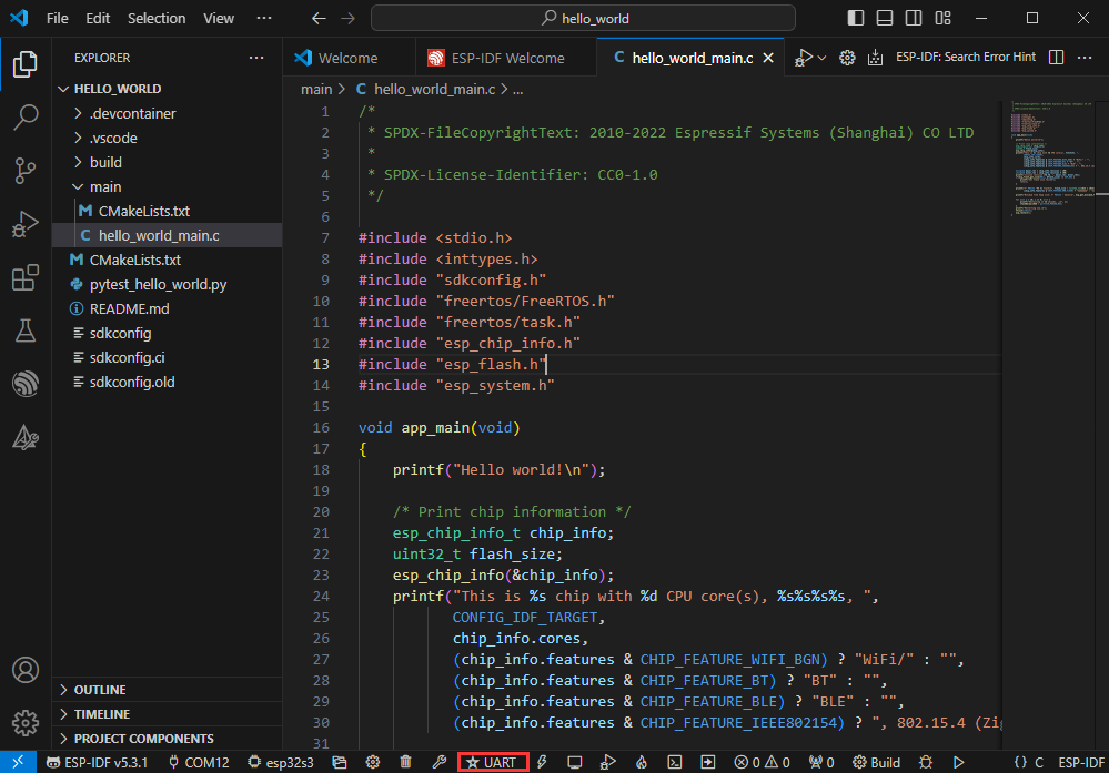
⑦.Current download mode, the default is UART
⑧.flash button, when a project build is completed, select the COM port of the corresponding development board, and click this button to flash the compiled firmware to the chip
⑨.monitor enable flashing port monitoring, when a project passes through Build --> Flash, click this button to view the log of output from flashing port and debugging port, so as to observe whether the application works normally
⑩.Debug
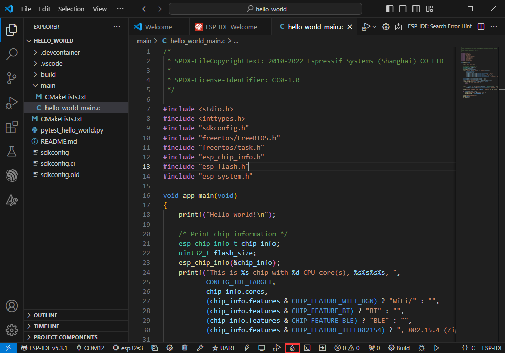
⑪.Build Flash Monitor one-click button, which is used to continuously execute Build --> Flash --> Monitor, often referred to as "little flame"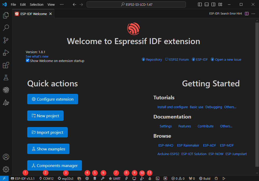
Compile, Flash and Serial Port Monitor
- Click on the all-in-one button we described before to compile, flash and open the serial port monitor
- It may take a long time to compile especially for the first time
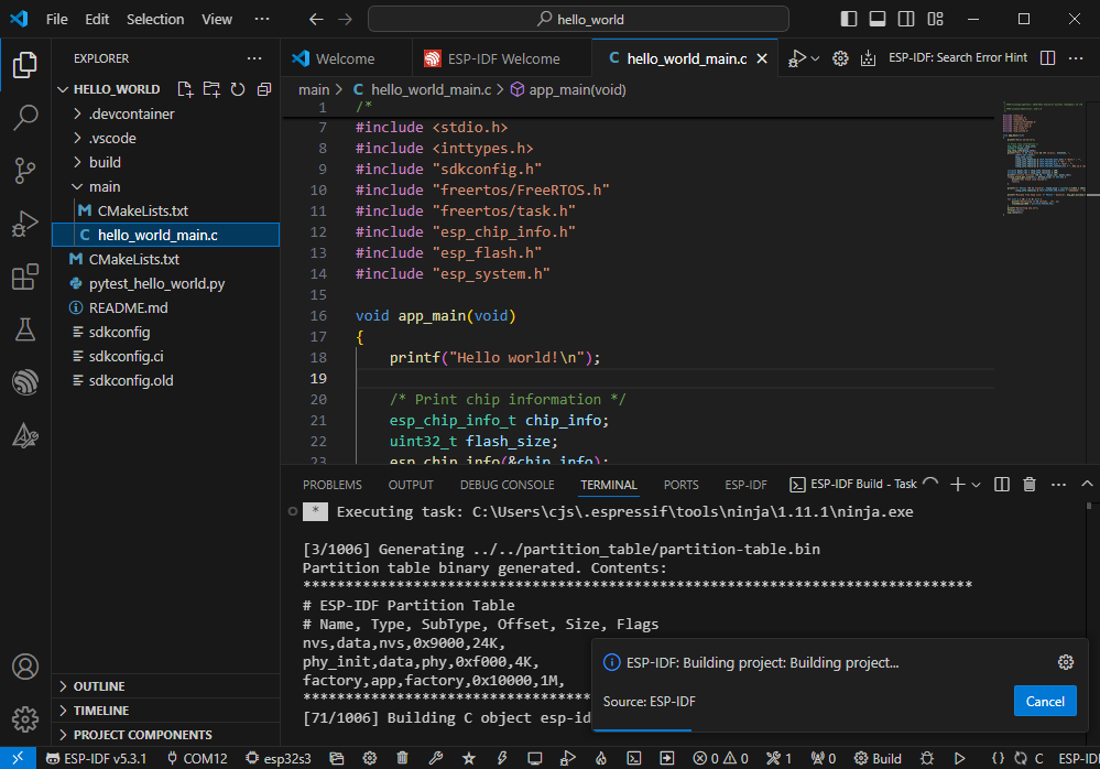
- During this process, the ESP-IDF may take up a lot of CPU resources, so it may cause the system to lag
- If it is the first time to flash the program for a new project, you will need to select the download method, and select UART
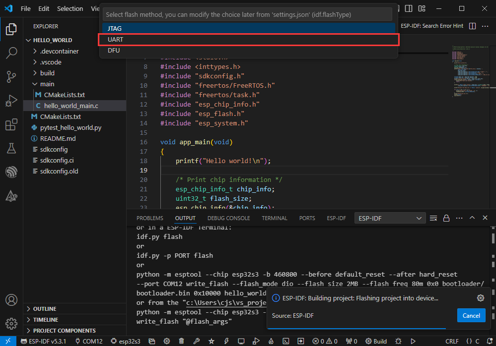
- This can also be changed later in the Download methods section (click on it to pop up the options)
- As it comes with the onboard automatic download circuit, it can be downloaded automatically without manual operation
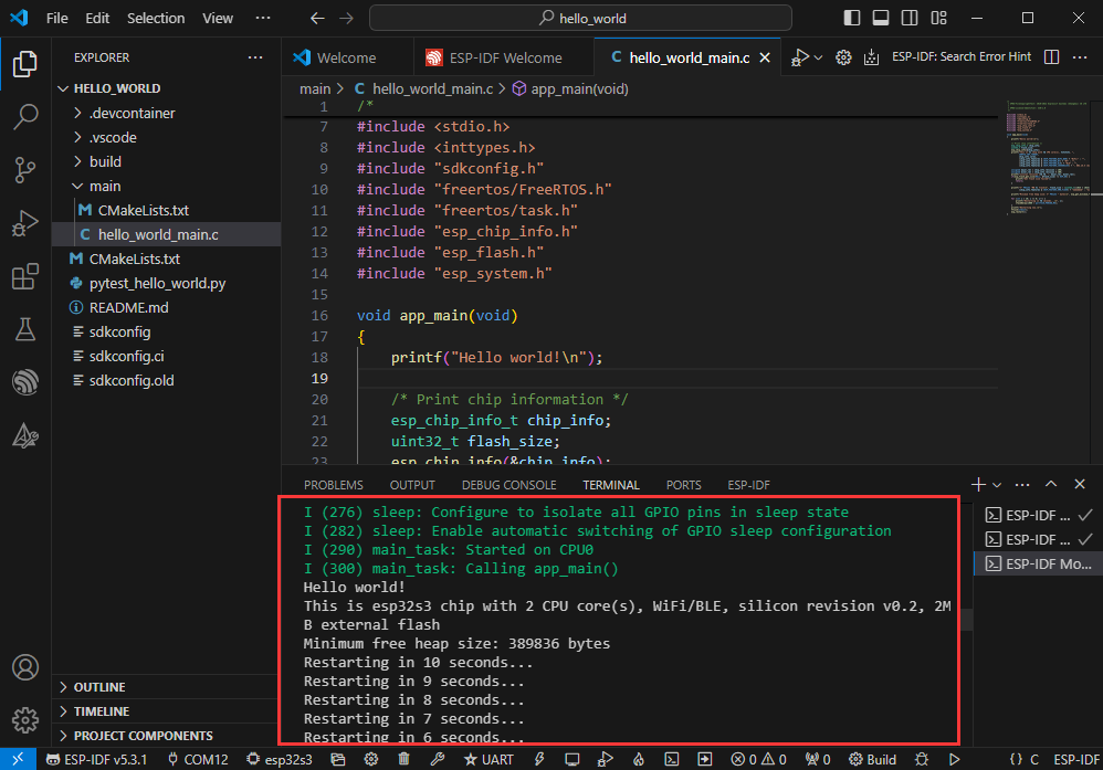
- After successful download, it will automatically enter the serial monitor, you can see the chip output the corresponding information and be prompted to restart after 10S
Use the IDF Demos
Open In the Software
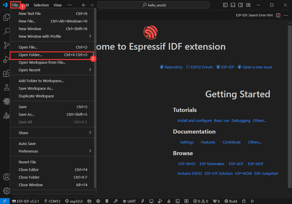
- Open VScode software and select the folder to open the demo
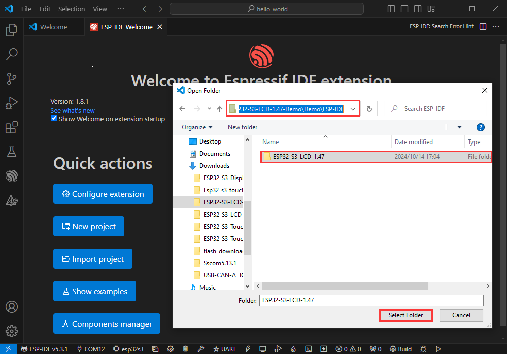
- Select the provided ESP-IDF example and click to select the file (located in the /Demo/ESP-IDF path under demo)
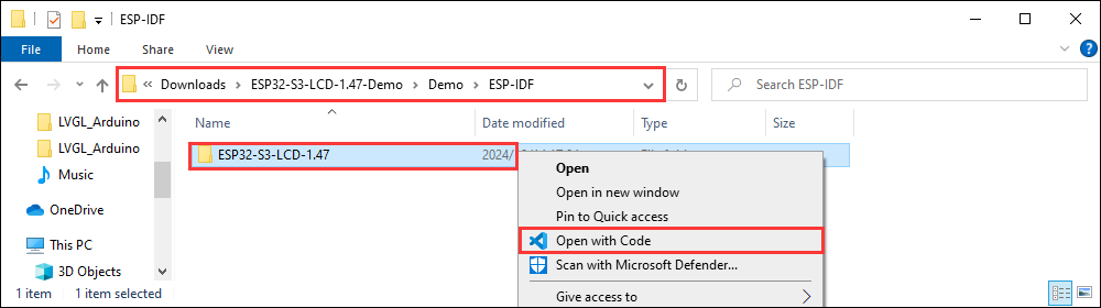
Open from Outside the Software
- Select the project directory correctly and open the project, otherwise it will affect the compilation and flashing of subsequent programs
- After connecting the device, select the COM port and model, click below to compile and flash to achieve program control
ESP-IDF Project Details
- Component: The components in ESP-IDF are the basic modules for building applications, each component is usually a relatively independent code base or library, which can implement specific functions or services, and can be reused by applications or other components, similar to the definition of libraries in Python development.
- Component reference: The import of libraries in the Python development environment only requires to "import library name or path", while ESP-IDF is based on the C language, and the importing of libraries is configured and defined through
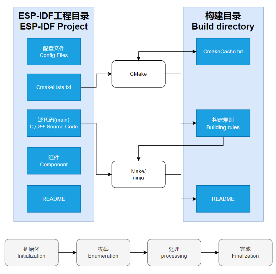
CMakeLists.txt. - The purpose of CmakeLists.txt: When compiling ESP-IDF, the build tool
CMakefirst reads the content of the top-levelCMakeLists.txtin the project directory to read the build rules and identify the content to be compiled. When the required components and demos are imported into theCMakeLists.txt, the compilation toolCMakewill import each content that needs to be compiled according to the index. The compilation process is as follows:
- Component reference: The import of libraries in the Python development environment only requires to "import library name or path", while ESP-IDF is based on the C language, and the importing of libraries is configured and defined through
Demo

| Demo | Basic Description | Dependency Library |
|---|---|---|
| 01_ADC_Test | Read the current voltage value of the system | - |
| 02_I2C_PCF85063 | Print the real time of the RTC chip | SensorLib |
| 03_I2C_QMI8658 | Print the raw data from IMU | SensorLib |
| 04_SD_Card | Load and display the information of the TF card | - |
| 05_WIFI_AP | Set to AP mode to obtain the IP address of the access device | - |
| 06_WIFI_STA | Set to STA mode to connect to WiFi and obtain an IP address | - |
| 07_LVGL_V8_Test | LVGLV8 demo | LVGL V8.3.11 |
| 08_LVGL_V9_Test | LVGLV9 demo | LVGL V9.3.0 |
01_ADC_Test
Demo description
- The analog voltage connected through the GPIO is converted to digital by the ADC, and then the actual lithium battery voltage is calculated and printed to the terminal.
Hardware connection
- Connect the board to the computer using a USB cable
Code analysis
- adc_bsp_init(void) : Initializes ADC1, including creating an ADC one-time trigger unit and configuring channel 3 for ADC1.
- adc_get_value(float *value,int *data) : Reads the value of ADC1 channel 3 and calculates the corresponding voltage value based on the reference voltage and resolution, stores it at the position where the incoming pointer points to, and stores 0 if the read fails.
- adc_example(void* parameter): Initialize ADC1 and then create an ADC task that reads the ADC value every 1 second and calculates the system's voltage based on the raw ADC value.
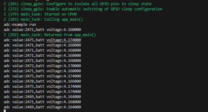
Result demonstration
- The program compilation download is complete, and opening the serial port monitor will show the printed ADC values and voltage, as shown in the following figure:
02_I2C_PCF85063
Demo description
- Through the I2C protocol, initialize the PCF85063 chip, set the time, and then periodically read the time and print it to the terminal
Hardware connection
- Connect the board to the computer using a USB cable
Code analysis
- void i2c_rtc_loop_task(void *arg) : Create an RTC task to implement RTC functionality, read the clock of the RTC chip every 1 seconds and then output it to the terminal
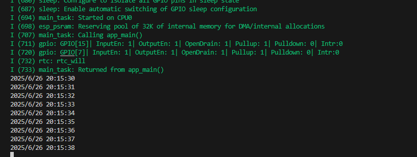
Result demonstration
- After the program is compiled and downloaded, open the serial port monitoring to see the RTC time of the printout, as shown in the following figure:
03_I2C_QMI8658
Demo description
- Through I2C protocol, initialize the QMI8658 chip, then read the corresponding attitude information every 200 milliseconds and print it to the terminal.
Hardware connection
- Connect the board to the computer using a USB cable
Code analysis
- void i2c_qmi_loop_task(void *arg) : Create a QMI task to obtain attitude information. In the task, read and print the accelerometer and gyroscope data, and output the obtained results to the serial port console at an interval of 200 milliseconds.
Result demonstration
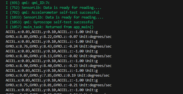
- Open the serial port monitoring, and you can see the original data output from the IMU (Euler angles need to be converted by yourself), as shown in the following figure:
04_SD_Card
Demo description
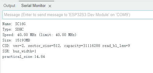
- Drive the TF card through SDMMC, and print the TF card information to the terminal after successfully mounting.
Hardware connection
- Install TF card in FatFs format on the board before powering on
Code analysis
- sdcard_init(void) : Initialize the TF card using the 1-wire SDMMC method.
- sdcard_loop_task(void *arg): A task to test TF card read and write functionality. You need to uncomment the
#define sdcard_write_Testmacro definition.
//#define sdcard_write_TestResult demonstration
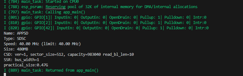
- Click on the serial port monitoring device, you can see the information of the output TF card, practical_size is the actual capacity of the TF card, as shown in the figure below:
05_WIFI_AP
Demo description
- This demo can set the development board as a hotspot, allowing phones or other devices in STA mode to connect to the development board.
Code analysis
- In the file
softap_example_main.c, findSSIDandPASSWORD, and then your phone or other device in STA mode can use the SSID and PASSWORD to connect to the development board.
#define EXAMPLE_ESP_WIFI_SSID      "waveshare_esp32"
#define EXAMPLE_ESP_WIFI_PASSWORD      "wav123456"
Result demonstration
After flashing the program, open the serial terminal, if the device is successfully connected to the hotspot, the MAC address and IP address of the device will be output, as shown in the figure: 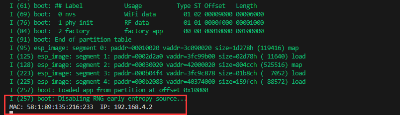
06_WIFI_STA
Demo description
- This example can configure the development board as a STA device to connect to the router and access the system network.
Code analysis
- In the file
esp_wifi_bsp.c, findssidandpassword, then modify them to the SSID and Password of the available router in your current environment.
wifi_config_t wifi_config = {
      .sta = {
        .ssid = "PDCN",
        .password = "1234567890",
      },
  };
Result demonstration
After flashing the program, open the serial terminal, if the device is successfully connected to the hotspot, the IP address obtained will be output, as shown in the figure: 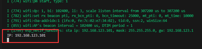
07_LVGL_V8_Test
Demo description
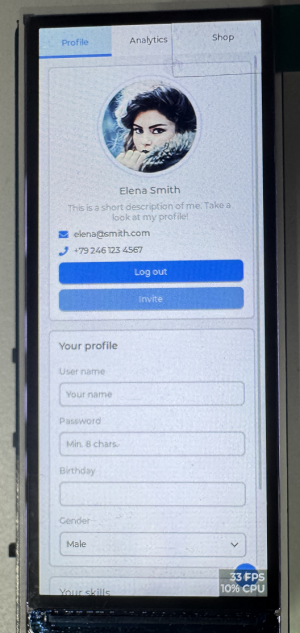
- Implement some multi-functional GUI interfaces on the screen by porting LVGL V8.
Hardware connection
- Connect the board to the computer using a USB cable
Code analysis
- If you need to rotate the display by 90 degrees, you can find the macro definition of
#define EXAMPLE_Rotate_90in the user_config.h file, and uncomment it. - If backlight testing is needed, you can find the macro definition of
#define Backlight_Testingin the user_config.h file, and uncomment it.
//#define Backlight_Testing
//#define EXAMPLE_Rotate_90
Result demonstration
- After the demo is flashed, the running result of the device is as follows:

08_LVGL_V9_Test
Demo description
- Implement some multi-functional GUI interfaces on the screen by porting LVGL V9.
Hardware connection
- Connect the board to the computer using a USB cable
Code analysis
- If you need to rotate the display by 90 degrees, you can find the macro definition of
#define EXAMPLE_Rotate_90in the user_config.h file, and uncomment it. - If backlight testing is needed, you can find the macro definition of
#define Backlight_Testingin the user_config.h file, and uncomment it.
//#define Backlight_Testing
//#define EXAMPLE_Rotate_90
Result demonstration
- After the demo is flashed, the running result of the device is as follows:
09_FactoryProgram
Demo description
- Comprehensive project, you can simply test the onboard hardware functions, or directly use the BIN firmware we provide for flashing.
Hardware connection
- Connect the board to the computer using a USB cable
Result demonstration
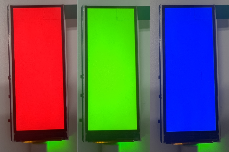
- The display screen transitions through red, green, and blue colors (with a transition interval of 1.5 seconds), as shown in the figure:
- After the RGB is displayed, it will automatically jump to the interface of testing the onboard hardware functions, as shown below:
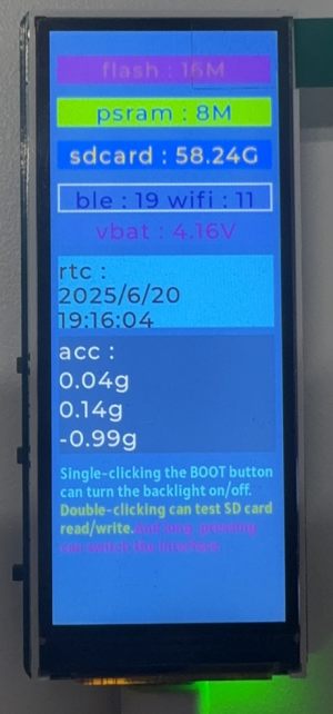
1. Display PSRAM and Flash stacked on the ESP32S3
2. Display the actual capacity of the inserted TF card
3. Scan the surrounding Bluetooth and Wi-Fi devices
4. Display the voltage of the connected lithium battery
5. Real-time display of RTC time and QMI gesture data
- Test button function, as shown in the figure:
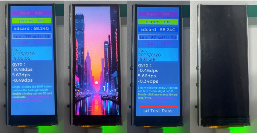
1. Click BOOT to switch the interface
2. Double-click to control the backlight
3. Long press to test the TF card read and write function. If sd Test Pass is displayed, it means the test has passed
Flash Firmware Flashing and Erasing
- The current demo provides test firmware, which can be used to test whether the onboard device functions properly by directly flashing the test firmware
- bin file path:
..\ESP32-S3-LCD-3.16-Demo\Firmware
Resources
Schematic Diagram
Demo
Datasheets
ESP32-S3
Other Components
Software Tools
Arduino
- Arduino IDE Official download link
- ESP32-Arduino official documentation
- Arduino-ESP32 offline component package
VScode
Firmware Flashing Tool
Other Resource Links
FAQ
Question: After the module downloads the demo and re-downloads it, why sometimes it can't connect to the serial port or the flashing fails?
- Long press the BOOT button, press RESET at the same time, then release RESET, then release the BOOT button, at this time the module can enter the download mode, which can solve most of the problems that can not be downloaded.
Question: Failed to set up the VSCode environment?
- First consider the network issue, try switching to another network
Question: Error when compiling an Arduino program?
- Check if the Arduino IDE -> Tools is correctly configured
Question: Is it stuck when sliding pictures displayed?
- Modify LVGL display cache to the full screen size
- Modify the LV_IMG_CACHE_DEF_SIZE option in the configuration to 1000 to achieve some optimization
Question: Can't display Chinese?
- Basic Chinese can be displayed, but if it is a rare character, it cannot be displayed
- You can transcode the required rare characters through the transcoding software, and then add them to the project font library
Question: How to deal with the first compilation of the program being extremely slow?
- It's normal for the first compilation to be slow, just be patient
Question: How to handle the display "waiting for download..." on the serial port after successfully ESP-IDF flashing?
- Press the reset button on the board
Question: What should I do if I can't find the AppData folder?
- Some AppData folders are hidden by default and can be set to show.
- English system: Explorer->View->Check "Hidden items"
- Chinese system: File Explorer -> View -> Display -> Check "Hidden Items"
Question: How do I check the COM port I use?
- Windows system:
①View through Device Manager: Press the Windows + R keys to open the "Run" dialog box; input devmgmt.msc and press Enter to open the Device Manager; expand the "Ports (COM and LPT)" section, where all COM ports and their current statuses will be listed.
②Use the command prompt to view: Open the Command Prompt (CMD), enter the "mode" command, which will display status information for all COM ports.
③Check hardware connections: If you have already connected external devices to the COM port, the device usually occupies a port number, which can be determined by checking the connected hardware.
- Linux system:
①Use the dmesg command to view: Open the terminal.
①Use the ls command to view: Enter ls /dev/ttyS* or ls /dev/ttyUSB* to list all serial port devices.
③Use the setserial command to view: Enter setserial -g /dev/ttyS* to view the configuration information of all serial port devices.
Question: Why does the program flashing fail when using a MAC device?
- Install MAC Driver and flash again.
Question: How to choose lithium battery and RTC battery?
- Normal 3.7V-4.2V positive PH1.25 terminal lithium battery
- The RTC battery range is 1.5 to 3.3V, and the terminal interface is SH1.0
Support
Monday-Friday (9:30-6:30) Saturday (9:30-5:30)
Email: services01@spotpear.com
[Tutorial Navigation]
- Introduction
- Usage Instructions
- Working with Arduino
- Working with ESP-IDF
- Environment Setup
- Run the First ESP-IDF Demo
- New Project
- Create Demo
- Modify COM Port
- Modify Driver Object
- Other Status Bar Functions
- Compile, Flash and Serial Port Monitor
- Use the IDF Demos
- Demo
- Flash Firmware Flashing and Erasing
- Resources
- FAQ
- Question: After the module downloads the demo and re-downloads it, why sometimes it can't connect to the serial port or the flashing fails?
- Question: Failed to set up the VSCode environment?
- Question: Error when compiling an Arduino program?
- Question: Is it stuck when sliding pictures displayed?
- Question: Can't display Chinese?
- Question: How to deal with the first compilation of the program being extremely slow?
- Question: How to handle the display "waiting for download..." on the serial port after successfully ESP-IDF flashing?
- Question: What should I do if I can't find the AppData folder?
- Question: How do I check the COM port I use?
- Question: Why does the program flashing fail when using a MAC device?
- Question: How to choose lithium battery and RTC battery?
- Support