- sales/support
Google Chat:---
- sales
+86-0755-88291180
- sales01
sales@spotpear.com
- sales02
dragon_manager@163.com
- support
tech-support@spotpear.com
- CEO-Complaints
zhoujie@spotpear.com
- Only Tech-Support
WhatsApp:13246739196
- Purchase/Shipping/Refund
WhatsApp:13424403025
- HOME
- >
- ARTICLES
- >
- Common Moudle
- >
- GSM-GPS
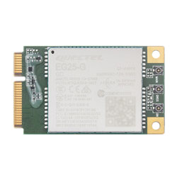
EG25-G-mPCIe User Guide
Overview
Introduction
EG25-G mPCIe is a globally recognized LTE Cat 4 wireless communication module that uses PCI Express Mini Card standard interface and is designed specifically for M2M and IoT applications. It supports LTE-TDD, LTE-FDD, HSPA+, GSM, GPRS, EDGE, and other wireless communication modes, as well as GPS, GLONASS, BDS, Galileo, and QZSS positioning technologies. It is suitable for industrial grade routers, industrial grade PDAs, tablets, video transmission, digital signage, remote monitoring, remote healthcare, etc.
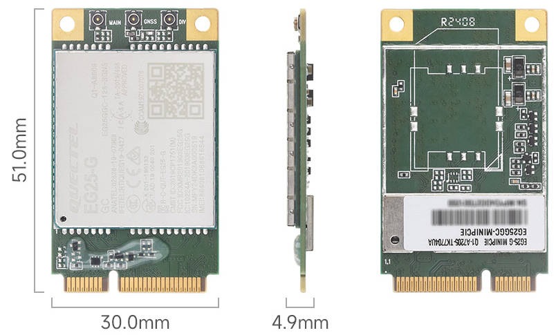
Dimensions
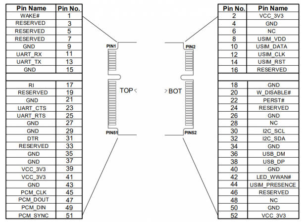
Pinout Definition
Feature
- Standard Mini PCIe interface, strong compatibility.
- Integrated with multi-satellite high-precision positioning GNSS receiver.
- Suitable for LTE, UMTS, and GSM networks with global coverage.
- EG25-G mPCIe series AT instructions are compatible with EG25-G series modules.
- MIMO technology meets the reliability requirements for data rate and connection in wireless communication systems.
Usage in Linux
Hardware Connection
Taking PCIe TO MiniPCIe GbE USB3.2 HAT+ connected to Raspberry Pi 5 as an example, please pay attention to cable direction and connect as shown in the figure: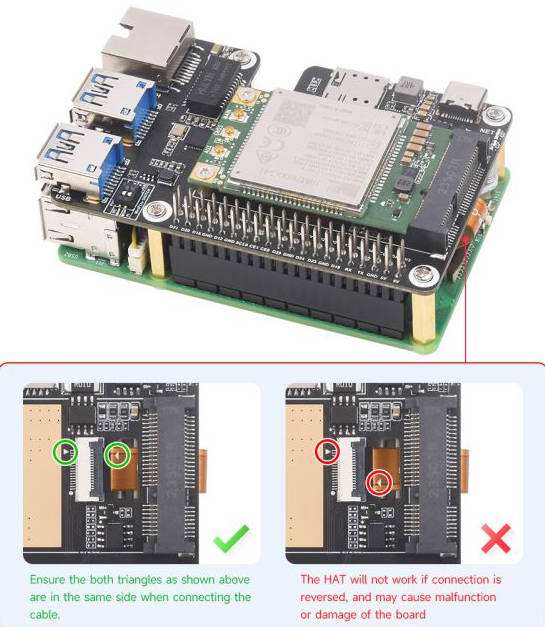
MBIM Dial-Up
1: Enable PCIE interface
PI5B does not have PCIE interface enabled by default. Add the following in /boot/firmware/config.txt:
dtparam=pciex1
2: Reboot PI5 after modification, and the device can be recognized.
As shown in the figure below, VL805 is recognized as our device, and the other PI5 is an RPI chip.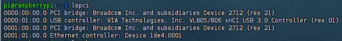
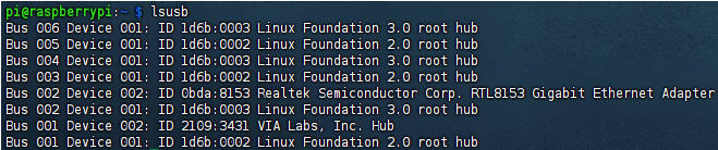
3: Execute lsusb and you can see that the USB device has been recognized.
DIP Switch Control
The onboard module dip switch is connected to GPIO6 of Raspberry Pi, you can switch it on and use Raspberry Pi to reset or switch on/off the module. (It is switched off by default (recommended). The board status is up to the Raspberry Pi, for example, if the Raspberry Pi shuts down, the board will power off.)
Onboard dip switch for switching MiniPCIe USB connection can be selected to connect Raspberry Pi through dip switch mode.
How to Install and Use Dial-up Tool (Required for module usage)
Input the following command to install waveshare-CM dial-up tool:
wget -O - https://files.waveshare.com/wiki/PCIe-TO-4G-5G-M.2-USB3.2-HAT-Plus/install.sh | sudo bash
After installation, if it cannot automatically dial up with NDIS(qmi) and MBIM, you can use the dial-up tool for Internet access. YOUR_APN means that your APN is using SIM card:
sudo waveshare-CM
# or
sudo waveshare-CM -s YOUR_APN
Usage in Windows
Install Driver
- Install driver directly: The default mode is VNet, and the driver can be installed directly, download Quectel Windows Driver Windows NDIS Driver package ->Uncompress and double-click to install->Continue clicking Next until Finish to complete the installation.
- Install driver manualy: For other dial-up modes, it doesn't work to install Ndis driver. It is recommended to manually install the driver, download Quectel Driver package->Ensure that the module has been powered on->Open Device Manager->Other Devices->Corresponding driver decompressed folder->Update driver->Browse my computer to find driver files->Select the path where the driver files are stored based on the system->Installation complete.
Send & Receive SMS Messages
Send English messages
- Install the SIM card and LTE antenna correctly, connect the module USB interface to the computer with a USB cable, and turn on the module.
- Check if the indicator lights are normal, PWR indicator light is always on, and NET light is flashing.
- AT+CMGF=1: Set SMS mode to TEXT.
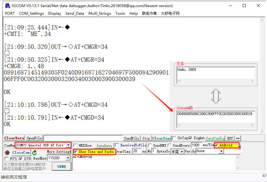
- AT+CMGS="phone number"<Enter>: set the recipient's phone number, and then return: ">". Send the required content such as "Best wish!", without the need to press enter at the end. Edit the text message and send 1A in hexadecimal format (1A is the key value of "CTRL+Z", used to tell the module to perform the sending operation, or send 1B, the key value of "ESC" to cancel the operation). If sending is successful, the module will return +CMGS: 15 to confirm this. As shown in the following figure.
Receive English messages
- Send a message on your phone saying 'This is a receive test for SIM7600X!' to the test module.
- When receiving a message, the serial port will report the message automatically: "SM", 20. It represents that there are 20 messages in SM, and the message just sent is the 20th one.
- Read messages: AT+CMGR=20 refers to reading the 20th message (AT+CMGL="ALL" means reading all messages).
- Delete messages: AT+CMGD=20, as shown in the following figure.
- Convert the displayed information into text using an encoding converter.
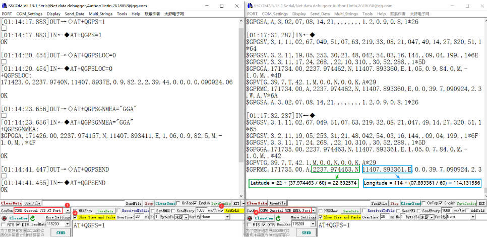
GNSS positioning
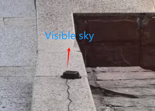
- Insert Active GPS Antenna into the GNSS antenna mount and place the receiver tag face down in an open outdoor area (note that it cannot be tested in rainy weather). It takes about 1 minute to receive the positioning signal when powered on.
- AT test instructions are as follows:
AT+QGPS=1	      //Open GPS
AT+QGPSLOC=0         //Print GPS information to serial port
AT+QGPSEND           //Close GPS
- Turn on GPS at the serial port for debugging in AT Port (Linux defaults to ttyUSB2), and then open NMEA port (Linux defaults to ttyUSB1) to obtain dynamic information.
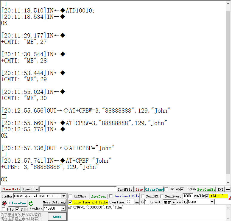
Address book
- AT test instructions are as follows:
AT+CPBW=3,"88888888",129,"John" //Add John's phone number into the address book
AT+CPBF="John"                  //Get John's phone number
ATD88888888;                    //Make a phone call
ATA	                        //Answer a call
AT+CHUP 	                //Hang up
- The test results are shown in the following figure:
Notes
1. Prohibit live plugging and unplugging of devices.
2. This module requires a voltage of around 3.6V to function perfectly.
3. Please confirm the interface before use. M.2 B KEY and MINI-PCIE interfaces are incompatible.
Resource
Datasheet
Driver Files
Software Tools
Imager
Support
Monday-Friday (9:30-6:30) Saturday (9:30-5:30)
Mobile: +86 13434470212
Email: services01@spotpear.com