- sales/support
Google Chat:---
- sales
+86-0755-88291180
- sales01
sales@spotpear.com
- sales02
dragon_manager@163.com
- support
tech-support@spotpear.com
- CEO-Complaints
zhoujie@spotpear.com
- sales/support
WhatsApp:13246739196
Banana PI BPI-Pico W-S3 User Guide
Overview
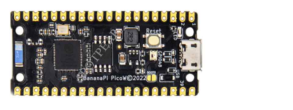
- The Banana Pi BPI-PicoW-S3 is a series of low-powered microcontrollers designed for IoT development. same size as Raspberry Pi Pico board,It supports 2.4 GHz Wi-Fi and Bluetooth® LE dual-mode wireless communication, the peripheral is compatible with low-power hardware design, and the power consumption is only 10uA in deep sleep mode.In terms of programming, the PicoW-S3 supports ESP-IDF, Arduino, micropython and other methods.
Features
- ESP32-S3, Xtensa® 32 bit LX7
- External PSRAM, FLASH
- Ultra-low power 10uA
- 2.4G WIFI, Bluetooth 5, Bluetooth mesh
- GPIO, ADC, TOUCH, PWM, I2C, SPI, RMT, I2S, UART, LCD, CAMERA, USB, JTAG
- 1 * microUSB
- 1 * Full color LED

BPI-PicoW-S3 VS Raspberry Pi PicoW, BPI-Leaf-S3, ESP32-S3-DevKitC-1
| Development board | BPI-PicoW-S3 | Rraspberry Pi PicoW | BPI-Leaf-S3 | ESP32-S3-DevKitC-1 |
|---|---|---|---|---|
| GPIO pinout | 27 | 27 | 36 | 36 |
| 3.3v pin | 1 | 1 | 2 | 2 |
| 5v pin | 2 | 2 | 1 | 1 |
| GND pin | 8 | 8 | 4 | 4 |
| Full color LED | 1 on GPIO48 | None | 1 on GPIO48 | 1 on GPIO48 |
| Chip directly connected to USB | MicroUSB port x1 | MicroUSB port x1 | Type-C USB port x1 | MicroUSB port x1 |
| UART TTL to USB | None | None | None | CP2102-MicroUSB interface x1 |
| External battery socket | None | None | 3.7v lithium battery power supply interface | None |
| Battery charging | None | None | 500mA charging | None |
| I²C 4pin connector | None | None | 1 | None |
Espressif ESP32-S3
Esp32-S3 is an MCU chip that integrates 2.4 GHz Wi-Fi and Bluetooth 5 (LE) and supports Long Range mode. The ESP32-S3 runs on an Xtensa® 32-bit LX7 dual-core processor with a high frequency of 240 MHz, 512 KB built-in SRAM (TCM), 45 programmable GPIO pins, and a rich communication interface. Esp32-s3 supports larger capacity of high-speed Octal SPI flash and off-chip RAM, and supports user-configured data caching and instruction caching.
What follows is a description of the most important features of ESP32-S3.
- Wi-Fi + Bluetooth 5 (LE) Wireless Connectivity: ESP32-S3 supports a 2.4 GHz Wi-Fi (802.11 b/g/n) with 40 MHz of bandwidth support. The Bluetooth Low Energy subsystem supports long range through Coded PHY and advertisement extension. It also supports higher transmission speed and data throughput, with 2 Mbps PHY. Both Wi-Fi and BLE have superior RF performance that is maintained even at high temperatures.
- AI Acceleration Support: ESP32-S3 has additional support for vector instructions in the MCU, which provides acceleration for neural network computing and signal processing workloads. The software libraries for the above-mentioned optimized functions will become available very soon, in the form of updates to ESP-DSP and ESP-NN.
- Rich IO interfaces: ESP32-S3 has 45 programmable GPIOs and common peripheral interfaces such as SPI, I2S, I2C, PWM, RMT, ADC, UART, SD/MMC host controller and TWAITM controller. Fourteen of the GPIOs can be configured as capacitive touch inputs for HMI interaction. In addition, ESP32-S3 is equipped with an ultra-low power coprocessor (ULP) and supports multiple low-power modes, making it widely applicable to various low-power application scenarios.
- Security mechanism: ESP32-S3 provides comprehensive security mechanism and protection measures for iot devices to prevent all kinds of malicious attacks and threats. It supports Flash encryption based on AES-XTS algorithm, secure startup based on RSA algorithm, digital signature and HMAC. Esp32-s3 also includes a new "World Controller" module, which provides two non-interfering execution environments to implement a trusted execution environment or permission separation mechanism.
Hardware interface

Hardware spec
| BPI-PicoW-S3 Spec Sheet | |
|---|---|
| SoC | ESP32-S3, Xtensa® 32-bit LX7 dual core |
| Basic frequency | 240MHz MAX |
| Operating temperature | -40℃~+85℃ |
| On-chip ROM | 384KB |
| On-chip SRAM | 320KB |
| Extereal FLASH | 8MB |
| In-packge PSRAM | 2MB |
| WIFI | IEEE 802.11 b/g/n, 2.4Ghz band, 150Mbps |
| Bluetooth | Bluetooth 5, Bluetooth mesh |
| GPIO | BPI-PicoW-S3 has led out 27 available GPIOs |
| ADC | 2 × 12-bit SAR ADC supporting 18 analog channel inputs |
| TOUCH Capacitive Touch Sensor | 14 |
| SPI | 4 |
| I2C | 2. Support master or slave mode |
| I2S | 2, input and output of serial stereo data |
| LCD | 1, support 8-bit ~16-bit parallel RGB, I8080, MOTO6800 interface |
| CAMERA | 1, supports 8-bit ~16-bit DVP image sensor interface |
| UART | 3, supports asynchronous communication (RS232 and RS485) and IrDA |
| PWM | 8 independent channels, 14-bit precision |
| MCPWM | 2 |
| USB | 1 × Full Speed USB 2.0 OTG, MicroUSB Female |
| USB Serial/JTAG Controller | 1, USB full speed standard, CDC-ACM, JTAG |
| Temperature sensor | 1, the measurement range is –20 °C to 110 °C, for monitoring the internal temperature of the chip |
| SD/MMC | 1 × SDIO host interface, with 2 card slots, supports SD card 3.0 and 3.01, SDIO 3.0, CE-ATA 1.1, MMC 4.41, eMMC 4.5 and 4.51 |
| TWAI® Controller | 1, compatible with ISO11898-1 (CAN specification 2.0) |
| Generic DMA Controller | 5 receive channels and 5 transmit channels |
| RMT | 4-channel transmit, 4-channel receive, shared 384 x 32-bit RAM |
| Pulse Counter | 4 pulse count controllers (units), each unit has 2 independent channels |
| Timer | 4 × 54-bit general-purpose timers, 16-bit clock prescaler, 1 × 52-bit system timer, 3 × watchdog timers |
| External crystal | 40Mhz |
| RTC and Low Power Management | Power Management Unit (PMU) + Ultra Low Power Coprocessor (ULP) |
| Low power consumption current | 10uA |
| Working Voltage | 3.3V |
| Input voltage | 3.3V~5.5V |
| Maximum discharge current | 2A@3.3V DC/DC |
| Controllable full color LED | 1 |
| Controllable monochrome LED | 1 |
Features

| BPI-PicoW-S3 size chart | |
|---|---|
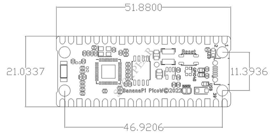
| Pin spacing | 2.54mm |
| Hole Spacing | 11.4mm/ 47mm |
| Hole size | Inner diameter 2.1mm/Outer diameter 3.4mm |
| Mainboard size | 21 × 51.88(mm)/0.83 x 2.04(inches) |
| Thickness | 1.2mm |
The pin spacing is compatible with universal boards (hole boards, dot matrix boards) and breadboards, which is convenient for debugging applications.
GPIO define
| BPI-PicoW-S3 peripheral GPIO pin assignment | ||
|---|---|---|
| Peripheral Interface | Signal | Pins |
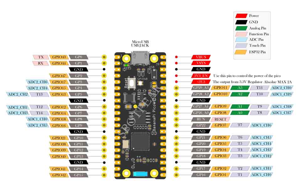
| ADC | ADC1_CH0~9 | GPIO 1~10 |
| ADC2_CH0~9 | GPIO 11~20 | |
| Touch Sensor | TOUCH1~14 | GPIO 1~14 |
| JTAG | MTCK | GPIO 39 |
| MTDO | GPIO 40 | |
| MTDI | GPIO 41 | |
| MTMS | GPIO 42 | |
| UART | Default assigned pins, can be redefined as any GPIO | |
| U0RXD_in | GPIO 44 | |
| U0CTS_in | GPIO 16 | |
| U0DSR_in | Any GPIO | |
| U0TXD_out | GPIO43 | |
| U0RTS_out | GPIO 15 | |
| U0DTR_out | Any GPIO | |
| U1RXD_in | GPIO 18 | |
| U1CTS_in | GPIO 20 | |
| U1DSR_in | Any GPIO | |
| U1TXD_out | GPIO 17 | |
| U1RTS_out | GPIO 19 | |
| U1DTR_out | Any GPIO | |
| U2 | Any GPIO | |
| I2C | Any GPIO | |
| PWM | Any GPIO | |
| I2S | Any GPIO | |
| LCD | Any GPIO | |
| CAMERA | Any GPIO | |
| RMT | Any GPIO | |
| SPI0/1 | Used for FLASH and PSRAM | |
| SPI2/3 | Any GPIO | |
| Pulse Counter | Any GPIO | |
| USB OTG | D- | GPIO 19 (internal PHY) |
| D+ | GPIO 20 (internal PHY) | |
| VP | GPIO 42 (External PHY) | |
| VM | GPIO 41 (External PHY) | |
| RCV | GPIO21 (External PHY) | |
| OEN | GPIO 40 (External PHY) | |
| VPO | GPIO 39 (External PHY) | |
| VMO | GPIO38 (External PHY) | |
| USB Serial/JTAG | D- | GPIO 19 (internal PHY) |
| D+ | GPIO 20 (internal PHY) | |
| VP | GPIO 42 (External PHY) | |
| VM | GPIO 41 (External PHY) | |
| OEN | GPIO 40 (External PHY) | |
| VPO | GPIO 39 (External PHY) | |
| VMO | GPIO38 (External PHY) | |
| SD/MMC | Any GPIO | |
| MCPWM | Any GPIO | |
| TWAI | Any GPIO | |
| Full Color LED | GPIO 48 | |
| Monochrome LED | GPIO 46 | |
Software
CircuitPython
CircuitPython is a programming language designed to simplify experimenting and learning to code on low-cost microcontroller boards.
Reference Resources :
ESP-IDF
ESP-IDF is an IoT development framework officially launched by Espressif, supporting Windows, Linux and macOS operating systems.
It is recommended that developers install ESP-IDF via an integrated development environment (IDE):
- GitHub: ESP-IDF Eclipse Plugin Installation and Usage Guide
- ESP-IDF VSCode plugin
- /master/docs/tutorial/toc.md GitHub: Installation and Usage Guide
- bilibili: ESP-IDF VSCode Plugin Quick Operation Guide
Or select the corresponding manual installation process according to the operating system:
API:
In order to enable your BPI-Leaf-S3 development board to flash FLASH through USB-CDC, you need to set the development board to firmware download mode.
There are two methods of operation:
1. Connect to the computer via USB, press and hold the BOOT button, then press the RESET button and release it, and finally release the BOOT button.
2. Press and hold the BOOT button when the power supply is disconnected, then connect to the computer via USB, and finally release the BOOT button.
You need to confirm the interface in the device manager. The serial number of the interface in the firmware download mode and the normal mode may be different.
MicroPython
MicroPython implements most of the features and syntax of Python 3, which is easy to learn and use, and can be downloaded directly into the chip to run the verification program without compiling.
Regardless of whether you have a programming foundation or not, MicroPython is far less difficult to get started with than other programming languages. Its code is easy to read, and the open source community has accumulated rich resources over the years. Just like Python, it has strong vitality and application value.
Arduino
Arduino is an open source embedded software and hardware development platform for users to create interactive embedded projects.
- Arduino IDE download address
- Install and configure
- Arduino-ESP32 operating environment
- GitHub: BPI-Leaf-S3 Arduino Quick Start
- Arduino-ESP32 APIs
Resources
BPI-PicoW-S3 schematic : https://github.com/BPI-STEAM/BPI-PicoW-Doc/blob/main/sch/BPI-PicoW-V0.4.pdf


