


- sales/support
Google Chat:---
- sales
+86-0755-88291180
- sales01
sales@spotpear.com
- sales02
dragon_manager@163.com
- support
tech-support@spotpear.com
- CEO-Complaints
zhoujie@spotpear.com
- Only Tech-Support
WhatsApp:13246739196
- Purchase/Shipping/Refund
WhatsApp:13424403025
2-CH RS485 HAT
Introduction
This is a dual-channel isolated RS485 extension board specially designed for raspberry PI, which adopts SC16IS752+SP3485 solution, embed with protection circuits such as power supply isolation, ADI magnetical isolation, and TVS diode, etc. It is easy to control the 2-channel RS485 for auto transceiving via SPI interface. Due to its fast communication, stability, reliability, and safety, it is an ideal choice for fields like industrial automation.
Interfaces
| VCC | 3.3V |
| PIN | Description |
| VCC | 3.3V/5V Power |
| GND | Ground |
| SCLK | SPI Clock input |
| MOSI | SPI Data input |
| MISO | SPI Data output |
| CS | SPI Chip Selection |
| IRQ | Interrupt output (Interrupt Request) |
| EN1 | Channel 1 output enable |
| EN2 | Channel 2 output enable |
Working principle
Introduction
This product adopts SC16IS752 as controller. SC16IS752 is a dual-channel high-performance UART expansion chip that supports SPI and I2C interfaces communication. This module uses SPI interface. Onboard power isolation, ADI magnetic coupler isolation, onboard TVS (transient voltage suppression tube), self-recovery fuses, protection diodes, and automatic transceiver switching circuit. It can effectively suppress the surge voltage and transient peak voltage in the circuit, prevent lightning and static electricity, prevent over-voltage, improve the anti-impact ability, can conduct signal isolation, with high dependence, strong anti-interference, low power consumption advantages, etc.
Communication protocol
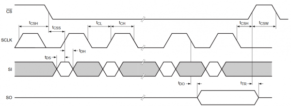
- CS:Slave chip selection, when CS is low, the slave chip is enabled.
- SCLK:SPI communication clock
- MOSI/SI:SPI Communication master sends, slave receives
- MOSI/SI:SPI Communication master receives, slave sends
- Timing Sequence:CPHL=0, CPOL=0 (SPI0)
How to use
We provide C and Python demo codes for Raspberry Pi. A quick testing example is provided in python.
Hardware Connection
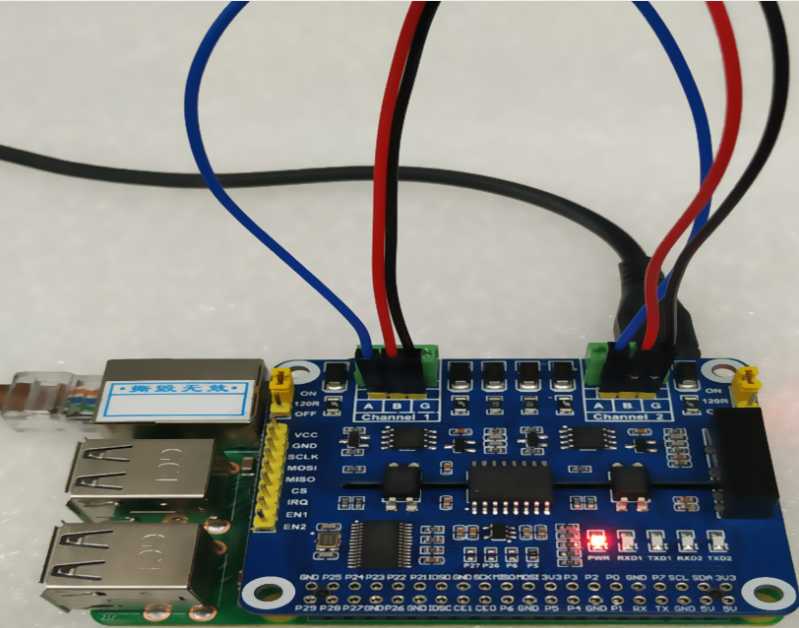
To run examples, you should prepare an external RS485 to UART module, connect it to Channel 1 of 2-CH RS485 HAT.
If you test the 2-CH RS485 HAT with the text.py example, you need to wire Channel 1 and Channel 2 of 2-CH RS485 HAT.
| 485 PIN | Raspberry Pi(BCM) |
| VCC | 5V |
| GND | GND |
| SCK | P21 (SPI1 SCLK) |
| MOSI | P20 (SPI1 MOSI) |
| MISO | P19 (SPI1 MISO) |
| CS | P18 (SPI1 CS) |
| IRQ | P24 |
| EN1 | P27 |
| EN2 | P22 |
Software setup
- Open the terminal and modify config.txt file by commands:
sudo nano /boot/config.txt
- Add the line below to the file, the int_pin should be set according to the actual welding:
dtoverlay=sc16is752-spi1,int_pin=24
- Then restart Raspberry Pi
sudo reboot
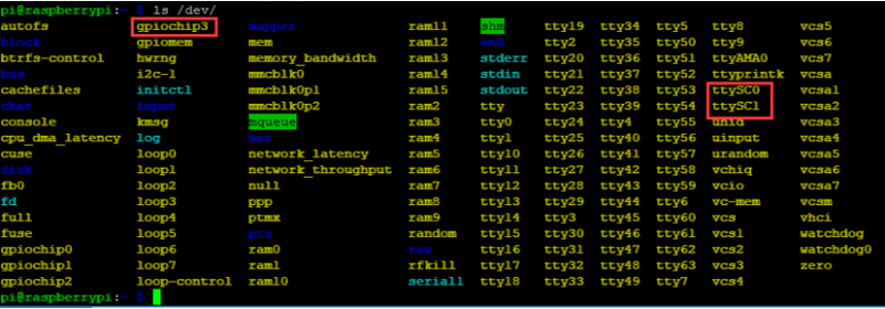
- After rebooting, the driver of SC16IS752 will be loaded into the system kernel. You can run command ls /dev to check the following devices:
Install Libraries
- Install wiringpi
sudo apt-get install wiringpi
# An upgrade may be required for raspberry PI 4B:
cd /tmp
wget https://project-downloads.drogon.net/wiringpi-latest.deb
sudo dpkg -i wiringpi-latest.deb
gpio -v
# Running gpio-v to check if the version is 2.52, If it is not, you need to check the installation again.
- Install the python2 library
sudo apt-get update
sudo apt-get install python-pip
sudo pip install RPi.GPIO
sudo apt-get install python-serial
- Install the python3 library
sudo apt-get update
sudo apt-get install python3-pip
sudo pip3 install RPi.GPIO
sudo apt-get install python3-serial
Test
- Download and run the examples:
sudo apt-get install p7zip-full
wget http://www.waveshare.net/w/upload/4/44/2-CH_RS485_HAT_code.7z
7z x 2-CH_RS485_HAT_code.7z
sudo chmod 777 -R  2-CH_RS485_HAT
cd 2-CH_RS485_HAT/
- You can also clone the project from our Github:
sudo git clone https://github.com/waveshare/2-CH-RS485-HAT
cd 2-CH-RS485-HAT/
- C program
cd c
make clean
make
sudo ./main
- Python program
cd python
cd examples
sudo python main.py
Hardware connection: Channel 1 of the 2-CH RS485 HAT is connected to the USB TO USB TO RS232/485/TTL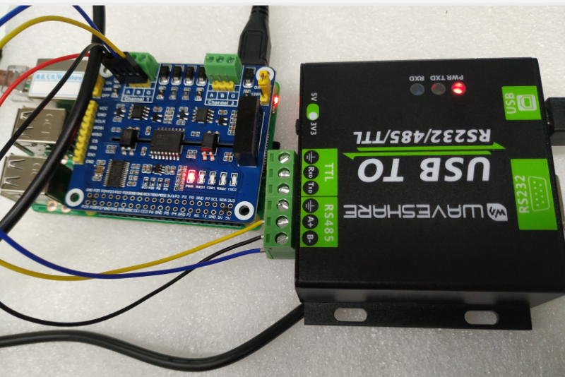
Connect USB TO USB TO RS232/485/TTL to the computer, open the serial port assistant software, select the corresponding serial port, and set the baud rate to 115200.
- Run the C program, the data sent by computer will all be received by Raspberry Pi, as below:
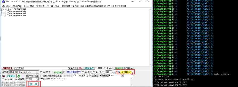
Note: The path of the samples is based on the actual directory;
- Run the main.py, the data sent by computer will all be received by Raspberry Pi, as below:
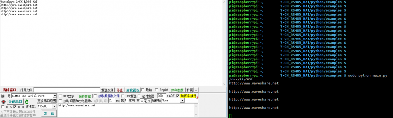
Note: The path of the samples is based on the actual directory;
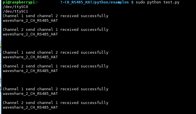
If you don't have other RS485 devices, you can choose the test method as follow by connecting channel 1 with channel 2:
- Running result of test.py :
.png)
.png)