


- sales/support
Google Chat:---
- sales
+86-0755-88291180
- sales01
sales@spotpear.com
- sales02
dragon_manager@163.com
- support
tech-support@spotpear.com
- CEO-Complaints
zhoujie@spotpear.com
- Only Tech-Support
WhatsApp:13246739196
- Purchase/Shipping/Refund
WhatsApp:13424403025
- HOME
- >
- ARTICLES
- >
- Common Moudle
- >
- Sensors
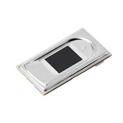
UART Fingerprint Sensor (F) User Guide
Introduction
It adopts a high-performance Cortex core as the main controller, integrates high security commercial fingerprint algorithms, and supports functions such as fingerprint enrollment, image acquisition, template extraction, and fingerprint comparison. There is no need to understand complex fingerprint recognition algorithms, and only need to send instructions through the serial port for secondary development. It can be quickly integrated into various fingerprint recognition applications with high volume and accuracy requirements.
- Built-in commercial algorithm, support fingerprint enrollment, fingerprint comparison, fingerprint image extraction and fingerprint template upload, etc., with stable performance and fast recognition speed
- Capacitive fingerprint recognition with sensitive sensing, allowing for quick recognition with just a gentle touch of the collection window
- High hardware integration, integrating the main controller and fingerprint sensor into one, making it easy to embed into small volume applications
- Built-in human body sensing device, with power-off sleep and touch wake-up functions, lower power consumption
- Fingerprint collection window with LED, providing fingerprint collection indication
- Onboard UART and USB dual communication ports
- Convenient for connecting to a PC for communication with the host computer, and also supports embedded hardware platforms such as STM32 and Raspberry Pi
Specifications
- Sensor type: Capacitive touch sensor
- Resolution: 508DPI
- Image pixel array: 192 x 192
- Module size: 20.4mm x 33.4mm
- Sensor sensing area: 9.6mm x 9.6mm
- Fingerprint count: 1000 pieces
- Matching time: < 0.5s (1:N, and N≤500)
- Operating voltage: 3.3V
- Operating current: <55mA
- Electrostatic discharge test: ESD IEC 61000-4-2 LEVEL 4 ±15KV air discharge
- Communication port: UART/USB
- Baudrate: 115200bps (support 9600bps ~ 115200bps)
- Operating environment:
- Temperature: -10~60 ℃
- Humidity: 20%RH ~ 80%RH (No condensation)
Onboard Interfaces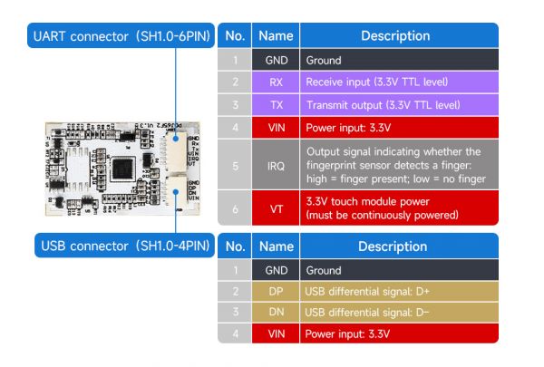
Hardware Operation Guide
Hardware Connection
After obtaining the module, the user can first test it using test software or demos. After having a certain understanding of the module, you can use the instruction list for secondary development.
The module can be controlled via the UART serial port or via the USB port.
UART Serial Port Connection
If you want to connect to the development board, you can use the UART serial port to connect.
| Fingerprint module | Target motherboard | Notes |
|---|---|---|
| GND | GND | Ground |
| RX | TX | UART data transmission pins, cross-wiring is required |
| TX | RX | UART data transmission pins, cross-wiring is required |
| VIN | 3.3V | 3.3V power supply input |
| IRQ | GPIO | Fingerprint touch detection pin, outputs high level when a finger touches, works with VT pin, can be connected to regular GPIO pins, can be connected to a regular GPIO pin and set to input state |
| VT | GPIO | Touch power supply pin, used in conjunction with the IRQ pin, can be connect to a regular GPIO |
USB Port Usage
It can be connected to the USB pin. If you design or customize the cables yourself, pay attention to the level conversion. The module only supports 3.3V level
Finger Operation Guide
This module uses high-precision components to collect fingerprints:
It can be recognized by gently touching the finger collection window, and there is no need to press hard on the fingerprint collection window.
- Correct ways

- Wrong ways

UART Port Control Instructions
1. Use the FT232 USB to UART serial port module for testing (if the user uses other USB to serial port modules, the operation is similar, the module needs to be purchased separately), and install the FT232 driver
2. Refer to the pin definition under UART Serial Port Connection to connect the module (note that RXD and TXD are cross-connected):
3. Connect the FT232 to the USB port of the PC, open the Device Manager, and check the corresponding COM port: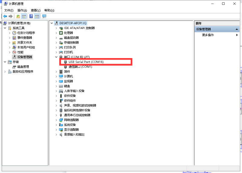
4. Download the test software: Capacitive-Fingerprint-Reader-(B)-Demo:
Open the software:
Select the corresponding communication method:
Serial: UART serial port communication
USB: USB communication
When choosing serial port communication, note to select the corresponding baud rate and serial port number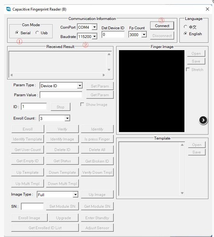
Software Description
Note: The host computer software provided can only support Windows PC
The Serial port operates in the same way as USB, and USB is used here for demonstration
Check Communication
Click "Adjust Sensor", if the connection is successful, you will receive the result shown in the figure: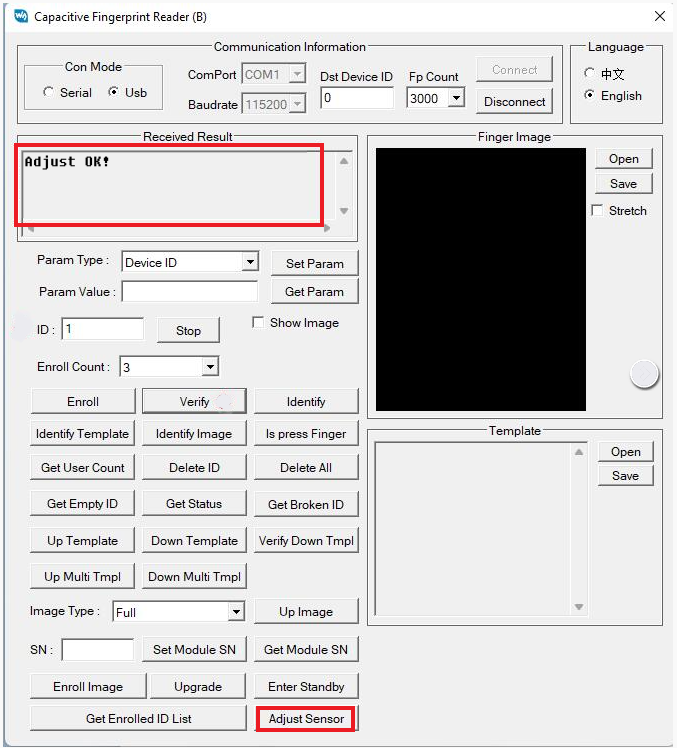
Set Parameters
Param Type:
Device ID: Indicates the device number of this module, and can be set within the following range: 1-255
Security Level: Indicates the security level, which can be set to values of 1-5. The higher the value, the lower the false acceptance rate (FAR), but the higher the false rejection rate (FRR).
Duplication Check: Fingerprint duplicate check status on/off (1/0).
Baudrate: The index of the baud rate.
Auto Learn: Indicates the self-learning status of the fingerprint template on/off (1/0).
Select the corresponding parameters, enter the corresponding parameter values, and click "Set Param" to change the parameters of the module; Click "Get Param" to get the current parameters of the module.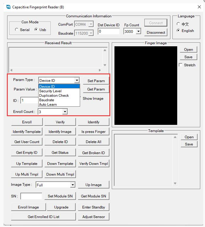
User Enroll
First, set up the ID (fingerprint storage number). Then, choose the "Enroll Count" (need to enter the fingerprints several times), and click "Enroll". Follow the prompts to operate step by step, and the final successful result will be as shown in the image.
If you don't know what ID to set, you can use "Get Empty ID," "Get Status," and "Get Enrolled ID List" to find available IDs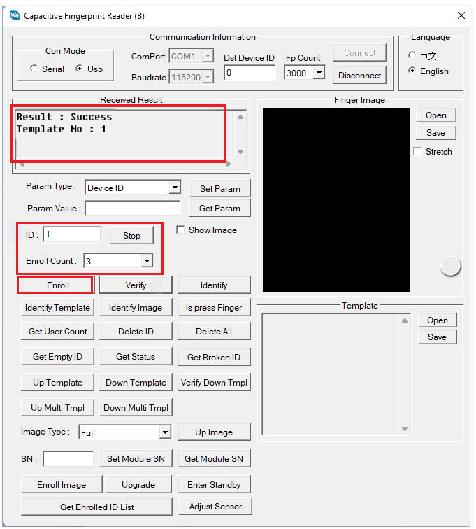
Fingerprint Recognition
Select the template fingerprint ID for comparison, click "Verify". If you have enabled the self-learning function, the comparison time will be slightly greater than 0.5S and will save the part of the fingerprint that is not stored for the finger.
Clicking "Identify" will automatically compare all enrolled fingerprints from 1 to 3000 (it will compare up to the set fingerprint count). It is a continuous comparison, meaning it will stop for about 0.5 seconds after a successful match and then automatically proceed to the next comparison.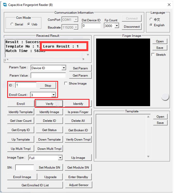
View Total User Count
1. Clicking "Get User Count" will query how many fingerprints have been enrolled in the module within the range of 1 to 1000 (the range queried will depend on the set fingerprint count).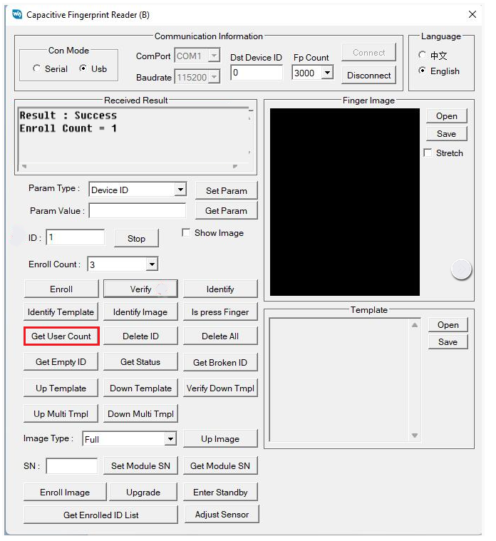
2. Click "Get Enrolled ID List", and it will query how many fingerprints have been enrolled in this module (it will query up to 1-3000 based on the set fingerprint count). Swipe through the results to see the IDs of the enrolled fingerprints.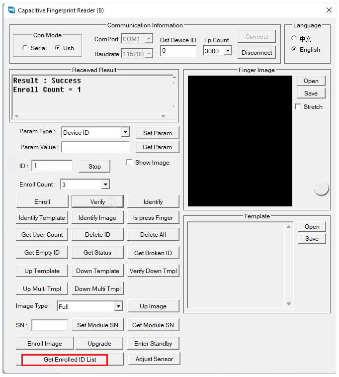
Get Empty ID
Click "Get Empty ID" to start querying from ID 1 for the first empty ID.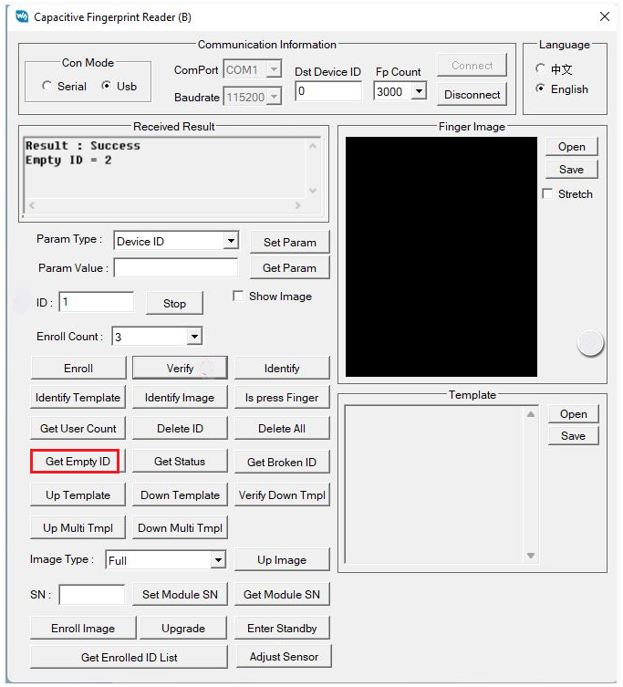
Get the enrollment status of the current ID number
Clicking on "Get Status" will show whether the storage space for the current ID number is empty. The image below indicates that the storage space for this ID number is not empty (i.e., the ID has been enrolled).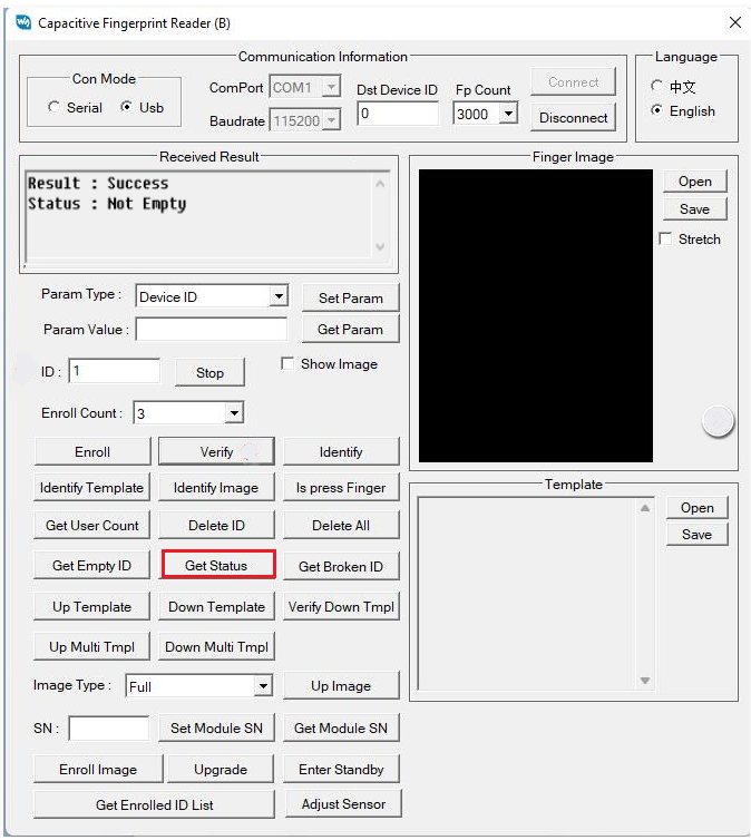
Delete Fingerprint
Click "Delete ID" to remove the fingerprint with the current ID number.
Click "Delete All" to delete all the fingerprints enrolled with IDs from 1 to 3000 (the range queried will depend on the set fingerprint count).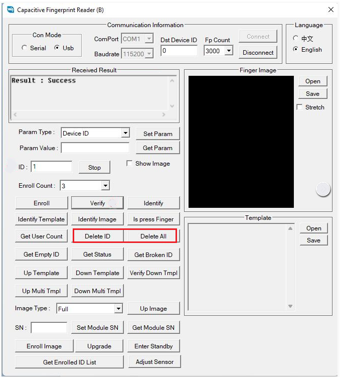
View Fingerprint Image (cannot view saved fingerprints)
Click "Up Image", then place your finger on the sensor.
You can also open "Show Image", so that every time you need to enter a fingerprint, the fingerprint image will be displayed (note: it is not recommended to use it in serial port mode, and it takes about 6 seconds to transfer image data).
You can choose to enable "Stretch" to show the fingerprint full-size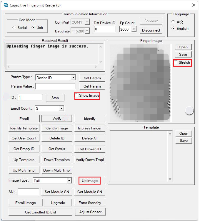
View Fingerprint Template (can only view saved fingerprints)
Select the ID number that has saved a fingerprint
Click "Up Template"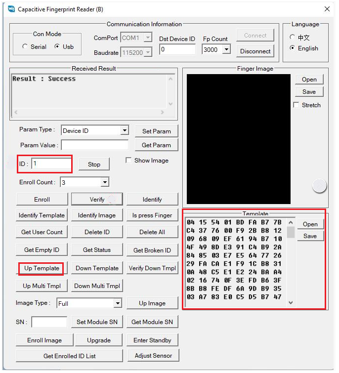
Click "Up Multi Tmpl" and select a folder to save the template files. It will upload fingerprint data numbered 1 to 3000 (the selected quantity of fingerprint count). The data will be stored in the chosen folder in FPT format.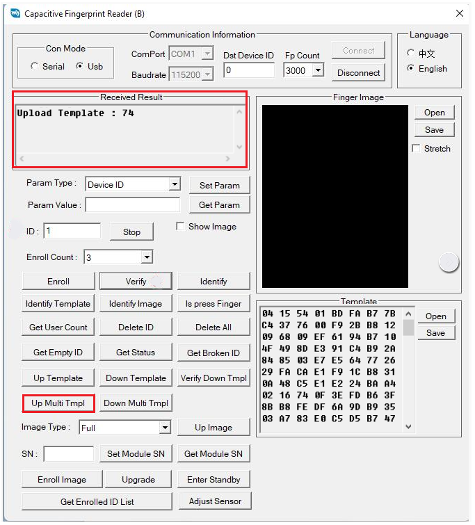

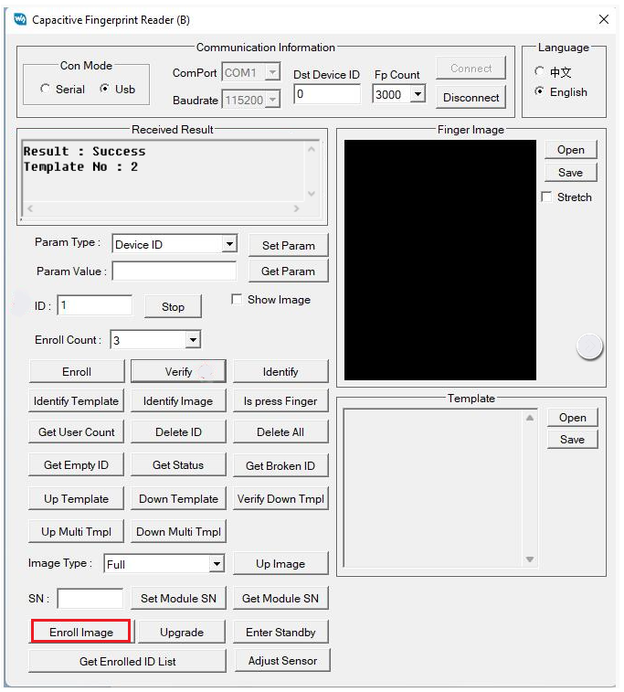
Enroll using Fingerprint Image
Configure the ID and the Enroll Count as specified in "User Enroll"
Click "Enroll Image" and select the fingerprint template image. The image size is 242*266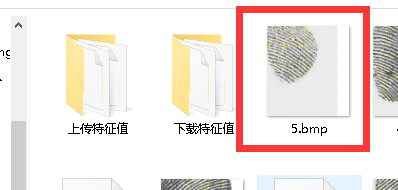
Enroll using Template
1. Single download
Configure the ID number.
Click on the "Open" shown in the image below, select an FPT format file, and click "Down Template".
2. Batch download
Click on "Down Multi Tmpl" and select the corresponding folder. All FPT format files in the folder will be downloaded to the module in the order they are sorted, with their ID numbers increasing sequentially.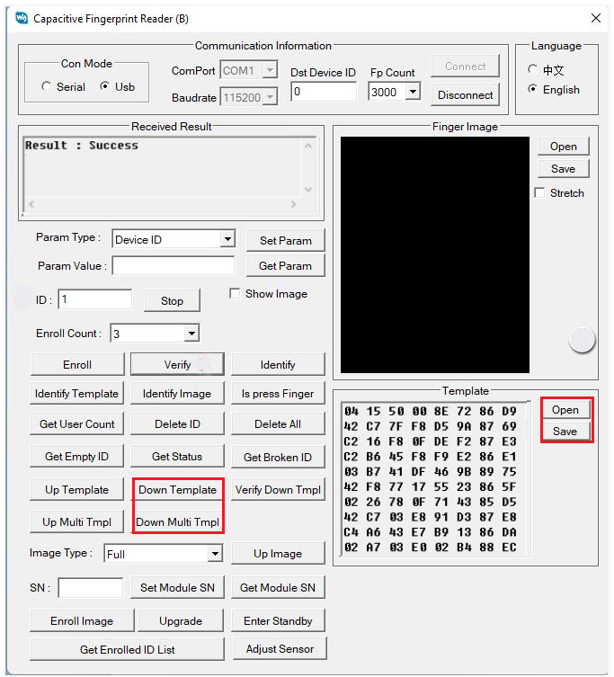
Identify using Fingerprint Image
Click on the "Open" as shown in the image, select the fingerprint image, and click "Identify Image".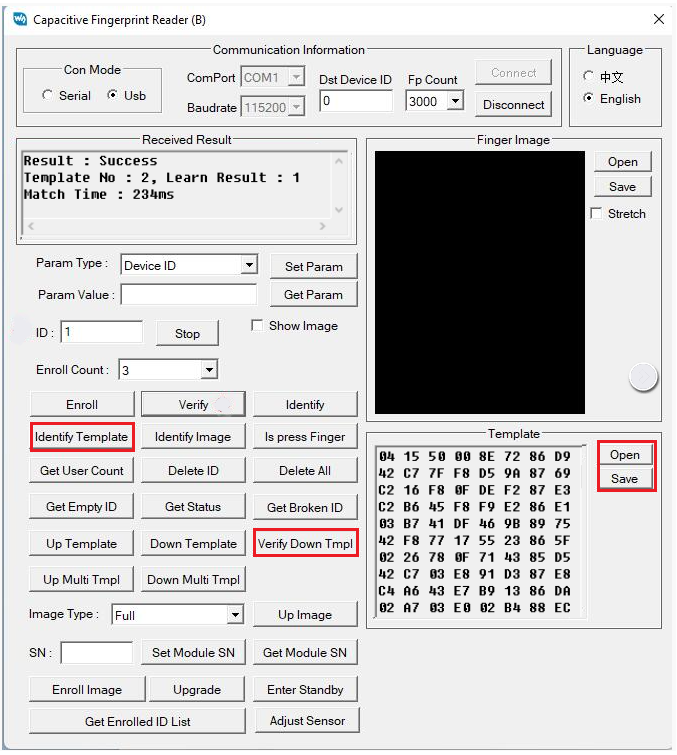
Identify using Template
Configure the ID and the Enroll Count as specified in "User Enroll"
Click the "Open" as shown in the image below, select an FPT format file, and then click "Identify Template" to compare with the fingerprint template within the chosen fingerprint ID number;
Click "Verify Down Tmpl" to compare with the fingerprint you are pressing.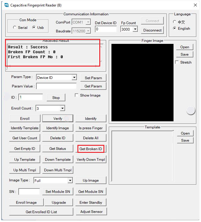
View Broken Template
Click "Get Broken ID", and the result will show the total number of broken templates and the number of the first broken template.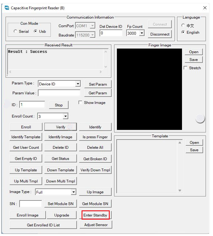
Standby
Click "Enter Standby"
After entering standby mode, no operations will respond, and you will only get a response after powering on again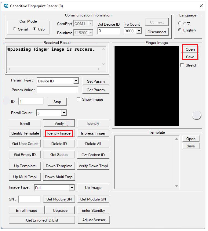
Demo
The function content for Raspberry Pi, Arduino, and STM32 may differ partially, but the operational methods and functionalities are the same.
Connection
| Module | STM32 | |
| VIN | 3.3V | Power input |
| GND | GND | Ground |
| TXD | PA10 | Module serial port transmitter |
| RXD | PA9 | Module serial port receiver |
| Module | Arduino | Function |
| VIN | 3.3V | Power input |
| GND | GND | Ground |
| TXD | 10 | Module serial port transmitter |
| RXD | 11 | Module serial port receiver |
| Module | Raspberry Pi | Function |
| VIN | 3.3V | Power input |
| GND | GND | Ground |
| TXD | RXD | Module serial port transmitter |
| RXD | TXD | Module serial port receiver |
Working with STM32/Arduino
Connect the corresponding STM32/Arduino with the fingerprint module according to the connection method
Connect the USB port of the Open103Z/Arduino UNO with the PC, and then choose the corresponding UART port:
Select the corresponding UART port: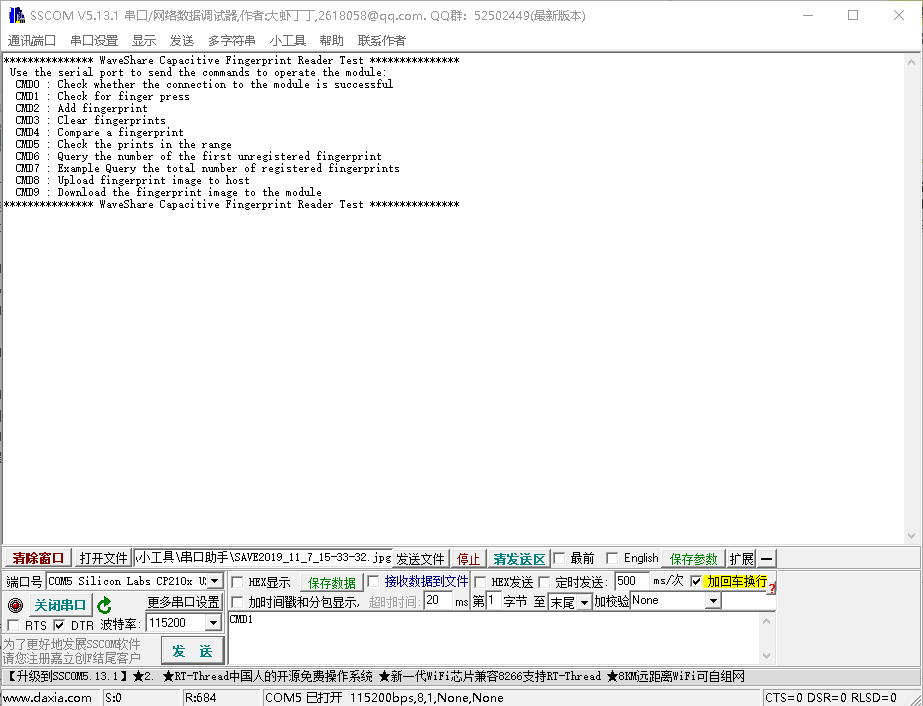
CMD0: Check if the connection is successful
CMD1: Check if a finger is detected
CMD2: Add a fingerprint
CMD3: Delete the fingerprint
CMD4: Verify the fingerprint
CMD5: Identify a fingerprint
CMD6: Query the ID of the first empty fingerprint
CMD7: Query the total number of fingerprints added
CMD8: Upload a fingerprint image to the host
CMD9: Download a fingerprint image to the module
Note: Arduino does not have CMD8 and CMD9 commands because of the memory, and packet loss will occur when using the 115200 baud rate, so it is recommended to use 57600 baud rate
How to modify:
1. Use the software to make modifications
2. Use the commands below to make modifications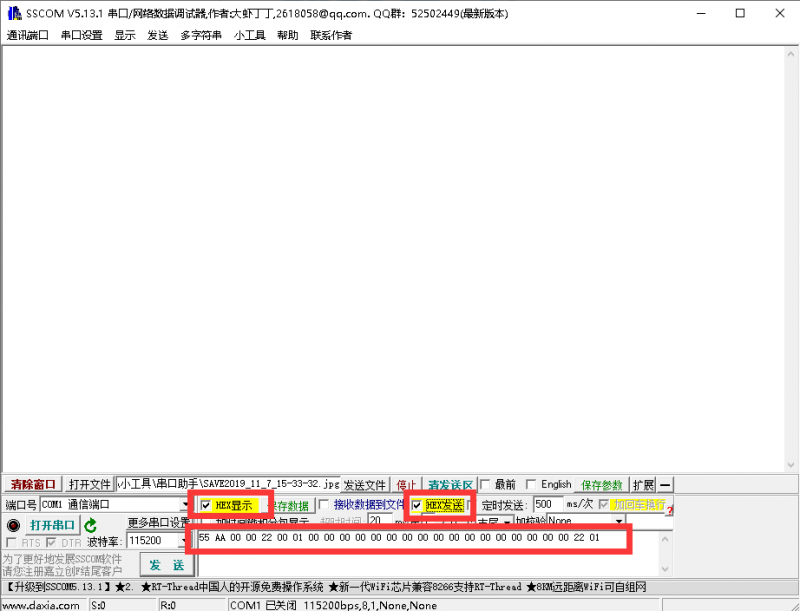
Set to 115200 baud rate:
55 AA 00 00 02 00 05 00 03 05 00 00 00 00 00 00 00 00 00 00 00 00 00 00 0e 01
Set to 57600 baud rate:
55 AA 00 00 02 00 05 00 03 04 00 00 00 00 00 00 00 00 00 00 00 00 00 00 0d 01
The return value after successful setup is:
AA 55 01 00 02 00 02 00 00 00 00 00 00 00 00 00 00 00 00 00 00 00 00 00 04 01
Working with Raspberry Pi
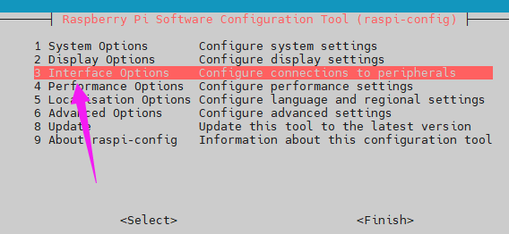
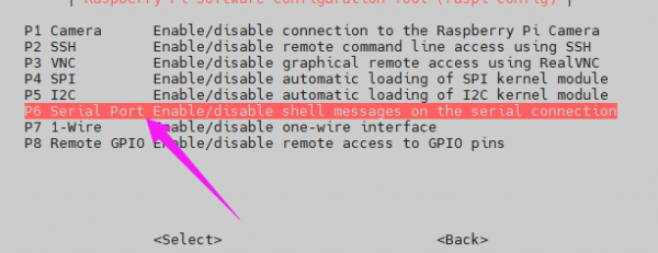
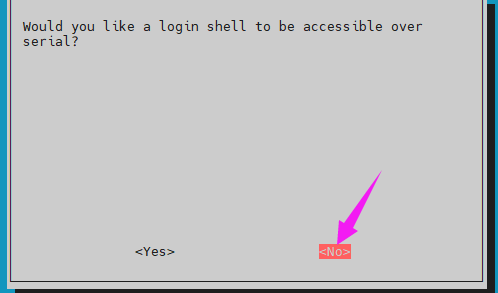
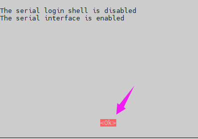
Enable UART Serial Port
Enter the command
sudo raspi-config
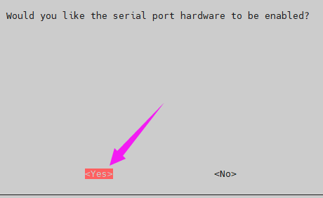
Reboot
sudo reboot
Install wiringpi
sudo apt install git-core
sudo git clone https://github.com/WiringPi/WiringPi
cd WiringPi/
sudo ./build
#Check the wiringpi version, usually above 2.70
gpio -v
Install Python Library
#Python3 serial port library
sudo apt-get install python3-serial
#Python2 serial port library
sudo apt-get install python-serial
Demo Download
wget https://files.waveshare.com/wiki/UART_Fingerprint_Sensor_F/Capacitive-Fingerprint-Reader-B-Code.zip
unzip unzip Capacitive-Fingerprint-Reader\(B\)-Code
cd cd Capacitive-Fingerprint-Reader\(B\)-Code/RaspberryPi/
Demo
c
cd c
make
sudo ./test
python
cd python
sudo python main.py
python3
cd python3
sudo python3 main.py
Demo Description
C File
fingerprint.h is used to save the main function of the demo running.
cmd.h is used to save your fingerprint image data.
Main Functions
- Initialization processing
First, process the data of the handshake signal. Then wait for the module initialization to complete, finally send the handshake signal. If the handshake is successful, proceed with the next operations. If not, wait for 1 second and attempt the handshake again, repeating this process up to 3 times.
void CMD_Init(void)
{
	uint8_t i = 0;
	Cmd_Packet_Init();
	Handshake_Signal();
	while (1)
	{
		Tx_cmd();
		if( Rx_cmd(1) )
		{
			printf("Connection closed by server\n\r");
			printf("Try to reconnect\n\r");
			if(i++ > 3)
			{
				printf("Power on the device again");
				while(1);
			}
		}
		else
			break;
		HAL_Delay(1000);
	}
}
- Waiting for module initialization mode selection
To cancel the comment on the fourth line, the waiting method is: wait 0.5 seconds To not cancel the comment on the fourth line, the waiting method is: wait for the module to send the initialization completion flag (this method must have the RST pin connected)
void Handshake_Signal(void)
{
// Select a power-on waiting mode
//#define CMD_DELAY
	#ifdef CMD_DELAY
		HAL_Delay(500);
	#else
		Handshake_flag = 1;
		HAL_GPIO_WritePin(Finger_RST_GPIO_Port,Finger_RST_Pin,GPIO_PIN_RESET);
		HAL_Delay(250);
		HAL_GPIO_WritePin(Finger_RST_GPIO_Port,Finger_RST_Pin,GPIO_PIN_SET);
		while (1)
		{
			if(flag == 1)
			{
				if(Handshake_data == 0x55)
				{
					Handshake_flag = 0;
					flag = 0;
					break;
				}
				else
				{
					printf("The communication fails. Power on the device again");
					while(1);
				}
			}
			HAL_Delay(1);
		}
	#endif
#undef CMD_DELAY
}
- Initialize the command structure
void Cmd_Packet_Init(void)
{
	CMD.PREFIX = Command;
	CMD.SID = Command_SID;
	CMD.DID = Command_DID;
	CMD.CMD = CMD_TEST_CONNECTION;
	CMD.LEN = DATA_0;
	for(int i = 0 ; i <CMD_Len ; i++)
		CMD.DATA[i] = 0x00;
}
- Receive user commands and process them
uint8_t Tx_Data_Process(void)
{
	while (1)
	{
		if( Usart2_ReceiveStruct.RX_flag == 1 )
		{
			Usart2_ReceiveStruct.RX_Size = 0;
			Usart2_ReceiveStruct.RX_flag = 0;
			flag = 0;
			if((Usart2_ReceiveStruct.RX_pData[0] == 'C') && (Usart2_ReceiveStruct.RX_pData[1] == 'M') && (Usart2_ReceiveStruct.RX_pData[2] == 'D'))
			{
				switch(Usart2_ReceiveStruct.RX_pData[3])
				{
					case '0': CmdTestConnection( 0 ) ; break;
					case '1': CmdFingerDetect( 0 ) ; break;
					case '2': AddUser( ) ; break;
					case '3': ClearUser( 0 ) ; break;
					case '4': VerifyUser( ) ; break;
					case '5': ScopeVerifyUser( ) ; break;
					case '6': CmdGetEmptyID( 0 ) ; break;
					case '7': GetUserCount( 1 ) ; break;
					case '8': CmdUpImageCode( 1 ) ; break;
					case '9': CmdDownImage( ) ; break;
				}
				break;
			}
		}
		HAL_Delay(1);
	}
	return 0;
}
- Build an array of commands and send it
void Tx_cmd(void)
{
	uint16_t 		CKS = 0 ;
	if(mode == 0 || mode == 2)
	{
		cmd[0] = CMD.PREFIX & 0xff;
		cmd[1] = (CMD.PREFIX & 0xff00) >> 8;
		cmd[2] = CMD.SID;
		cmd[3] = CMD.DID;
		cmd[4] = CMD.CMD ;
		cmd[5] = 0x00 ;
		cmd[6] = CMD.LEN & 0xff;
		cmd[7] = (CMD.LEN & 0xff00) >> 8;
		for(int i = 0 ; i < CMD.LEN ; i++)
			cmd[8+i] = CMD.DATA[i];
		for(int i = 0 ; i < 24 ; i++)
			CKS = CKS + cmd[i];
		cmd[24] = CKS & 0xff;
		cmd[25] = (CKS & 0xff00) >> 8;
		HAL_UART_Transmit(&huart1,cmd, 26,2);
	}
	else
	{
		cmd_data[0] = CMD_DATA.PREFIX & 0xff ;
		cmd_data[1] = (CMD_DATA.PREFIX & 0xff00) >> 8 ;
		cmd_data[2] = CMD_DATA.SID ;
		cmd_data[3] = CMD_DATA.DID ;
		cmd_data[4] = CMD_DATA.CMD ;
		cmd_data[5] = 0x00 ;
		cmd_data[6] = CMD_DATA.LEN & 0xff;
		cmd_data[7] = (CMD_DATA.LEN & 0xff00) >> 8;
		if(SN <129 )
		{
			for(int i = 0 ; i < CMD_DATA.LEN ; i++)
				cmd_data[8+i] = CMD_DATA.DATA[i];
			for(int i = 0 ; i < 506 ; i++)
				CKS = CKS + cmd_data[i];
			cmd_data[506] = CKS & 0xff;
			cmd_data[507] = (CKS & 0xff00) >> 8;
			HAL_UART_Transmit(&huart1,cmd_data, 508 , 44);
		}
		else
		{
			for(int i = 0 ; i < CMD_DATA.LEN ; i++)
				cmd_data[8+i] = CMD_DATA.DATA[i];
			for(int i = 0 ; i < 398 ; i++)
				CKS = CKS + cmd_data[i];
			cmd_data[398] = CKS & 0xff;
			cmd_data[399] = (CKS & 0xff00) >> 8;
			HAL_UART_Transmit(&huart1,cmd_data, 400,38);
		}
	}
}
- Process the received response array
uint8_t Rx_cmd( uint8_t back )
{
	uint8_t a=1;
	uint16_t 		CKS = 0 ;
	while(a)
	{
		if(flag == 1)
		{
			a = 0;
			flag = 0;
			if(rps[4] == 0xff)
				return 1;
			Rx_CMD_Process();
			if(mode == 0)
			{
 				for(int i = 0 ; i < 24 ; i++)
					CKS = CKS + rps[i];
				if(CKS == RPS.CKS)
					return Rx_Data_Process(back);
			}
			else
			{
				for(int i = 0 ; i < 10 ; i++)
					CKS = CKS + rps[i];
				if(CKS == RPS.CKS)
					return 0;
				else
					return RPS.CMD;
			}
		}
		HAL_Delay(1);
	}
	return 1;
}
- Update received command structure
void Rx_CMD_Process(void)
{
	RPS.PREFIX = rps[0] + rps[1] * 0x100;
	RPS.SID = rps[2];
	RPS.DID = rps[3];
	RPS.CMD = rps[4] + rps[5] * 0x100;
	RPS.LEN = rps[6] + rps[7] * 0x100;
	RPS.RET = rps[8] + rps[9] * 0x100;
	if(mode == 0)
	{
		for(int i=0 ; i<RPS_Len ; i++)
			RPS.DATA[i] = rps[10 +i];
		RPS.CKS = rps[24] + rps[25] * 0x100;
	}
	else
		RPS.CKS = rps[10] + rps[11] * 0x100;
}
- Process response data
uint8_t Rx_Data_Process( uint8_t back )
{
	uint8_t a=0;
	switch(RPS.CMD)
	{
		case CMD_TEST_CONNECTION: a = RpsTestConnection(back); break;
		case CMD_FINGER_DETECT: a = RpsFingerDetect(back) ; break;
		case CMD_GET_IMAGE: a = RpsGetImage(back); break;
		case CMD_GENERATE: a = RpsGenerate(back); break;
		case CMD_MERGE: a = RpsMerge(back); break;
		case CMD_DEL_CHAR : a = RpsDelChar(back); break;
		case CMD_STORE_CHAR: a =RpsStoreCher(back) ; break;
		case CMD_SEARCH: a = RpsSearch(back) ; break;
		case CMD_VERIFY: a= RpsVerify(back) ; break;
		case CMD_GET_EMPTY_ID : a = RpsGetEmptyID(back); break;
		case CMD_GET_ENROLL_COUNT : a = RpsGetEnrollCount(back); break;
		case CMD_DOWN_IMAGE : a = RpsDownImage(back); break;
	}
	return a;
}
- Response and error code list
uint8_t RPS_RET(void)
{
	switch(RPS.RET)
	{
		case ERR_SUCCESS: printf("Instruction processing succeeded\r\n"); break;
		case ERR_FAIL: printf("Instruction processing failure\r\n"); break;
		case ERR_TIME_OUT: printf("No prints were entered within the time limit\r\n"); break;
		case ERR_FP_NOT_DETECTED: printf("There is no fingerprint input on the collector\r\n"); break;
		case ERR_FP_CANCEL: printf("Instruction cancelled\r\n"); break;
		case ERR_INVALID_BUFFER_ID: printf("The Ram Buffer number is invalid\r\n"); break;
		case ERR_BAD_QUALITY: printf("Poor fingerprint image quality\r\n"); break;
		case ERR_GEN_COUNT: printf("Invalid number of combinations\r\n"); break;
		case ERR_INVALID_TMPL_NO: printf("The specified Template number is invalid\r\n"); break;
		case ERR_DUPLICATION_ID: printf("The fingerprint has been registered, and the id is : %d\r\n",RPS.DATA[0]+RPS.DATA[1]*0x100 ); break;
		case ERR_INVALID_PARAM: printf("Specified range invalid\r\n"); break;
		case ERR_TMPL_EMPTY: printf("Template is not registered in the specified range\r\n"); break;
		case ERR_VERIFY: printf("Description Failed to specify fingerprint comparison\r\n"); break;
 		case ERR_IDENTIFY: printf("Fingerprint comparison failed for the specified range\r\n"); break;
	}
	return RPS.RET;
}
Resources
Document
Demo
Softwares
Support
Monday-Friday (9:30-6:30) Saturday (9:30-5:30)
Email: services01@spotpear.com
[Tutorial Navigation]
- Introduction
- Specifications
- Onboard Interfaces
- Hardware Operation Guide
- Hardware Connection
- UART Serial Port Connection
- USB Port Usage
- Finger Operation Guide
- UART Port Control Instructions
- Software Description
- Check Communication
- Set Parameters
- User Enroll
- Fingerprint Recognition
- View Total User Count
- Get Empty ID
- Delete Fingerprint
- View Fingerprint Image (cannot view saved fingerprints)
- View Fingerprint Template (can only view saved fingerprints)
- Enroll using Fingerprint Image
- Enroll using Template
- Identify using Fingerprint Image
- Identify using Template
- View Broken Template
- Standby
- Demo
- Connection
- Working with STM32/Arduino
- Working with Raspberry Pi
- Demo Description
- Resources
- Support