- sales/support
Google Chat:---
- sales
+86-0755-88291180
- sales01
sales@spotpear.com
- sales02
dragon_manager@163.com
- support
tech-support@spotpear.com
- CEO-Complaints
zhoujie@spotpear.com
- Only Tech-Support
WhatsApp:13246739196
- Purchase/Shipping/Refund
WhatsApp:13424403025
- HOME
- >
- ARTICLES
- >
- Common Moudle
- >
- LCD
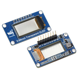
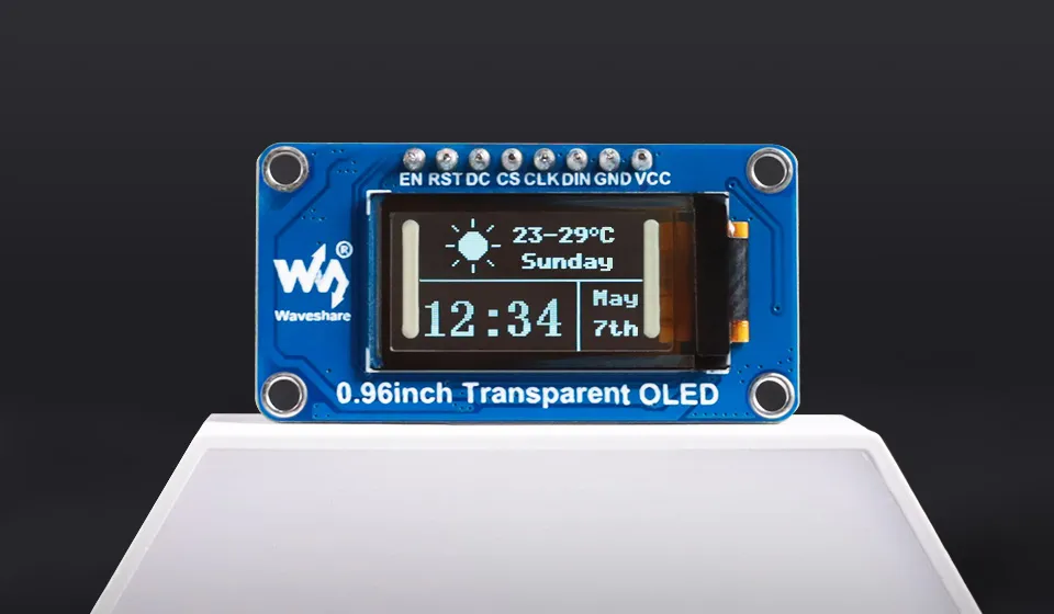
0.96inch Transparent OLED User Guide
Specifications
| Parameter | Specification |
|---|---|
| Operating Voltage | 3.3V |
| Display Panel | OLED |
| Resolution | 128 × 64 pixels |
| Pixel Size | 0.15 × 0.15 (mm) |
| Communication Interface | 4-wire SPI (default) / I2C (solder pad switch) |
| Driver IC | SSD1312 |
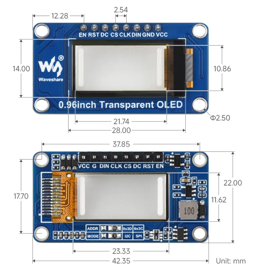
| Display Size | 10.86 × 21.74 (mm) |
| Product Dimensions | 22.00 × 42.35 (mm) |
| Display Color | White |
Interface Description
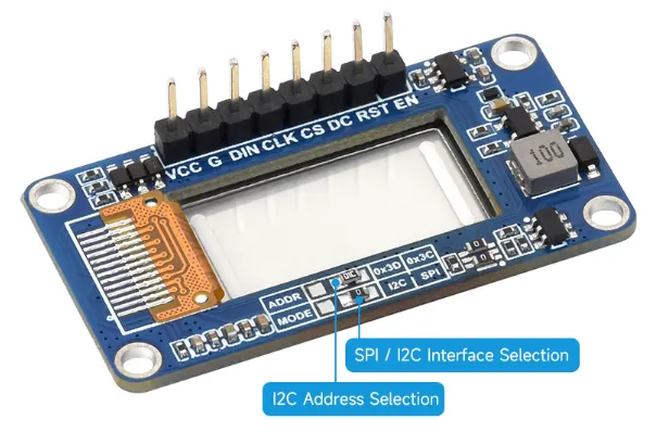
| Pin | Description |
|---|---|
| VCC | Power supply positive (3.3V power input) |
| GND | Ground |
| DIN | Data input |
| CLK | Clock signal input |
| CS | Chip select, active low |
| DC | Data/Command pin, low for command, high for data |
| RST | Reset pin, active low |
| EN | Power enable pin, enabled by default |
Dimensions
ESP-IDF
This chapter includes the following sections. Please read as needed:
ESP-IDF Getting Started
New to ESP32 ESP-IDF development and looking to get started quickly? We have prepared a general Getting Started Tutorial for you.
- Section 1: Environment Setup
- Section 2: Running Examples
- Section 3: Creating a Project
- Section 4: Using Components
- Section 5: Debugging
- Section 6: FreeRTOS
- Section 7: Peripherals
- Section 8: Wi-Fi Programming
- Section 9: BLE Programming
Please Note: This tutorial uses the ESP32-S3-Zero as a teaching example, and all hardware code is based on its pinout. Before you start, it is recommended that you check the pinout of your development board to ensure the pin configuration is correct.
Setting Up the Development Environment
The following guide uses Windows as an example, demonstrating development using VS Code + the ESP-IDF extension. macOS and Linux users should refer to the official documentation.
The screenshots in this section use ESP-IDF V5.5.2 as an example. When installing, please select the ESP-IDF version that matches your board's example.
Install the ESP-IDF Development Environment
Download the installation manager from the ESP-IDF Installation Manager page. This is Espressif's latest cross-platform installer. The following steps demonstrate how to use its offline installation feature.
Click the Offline Installer tab on the page, then select Windows as the operating system and the ESP-IDF version you need (the version shown in the screenshot is for reference only — choose the version that fits your actual needs).
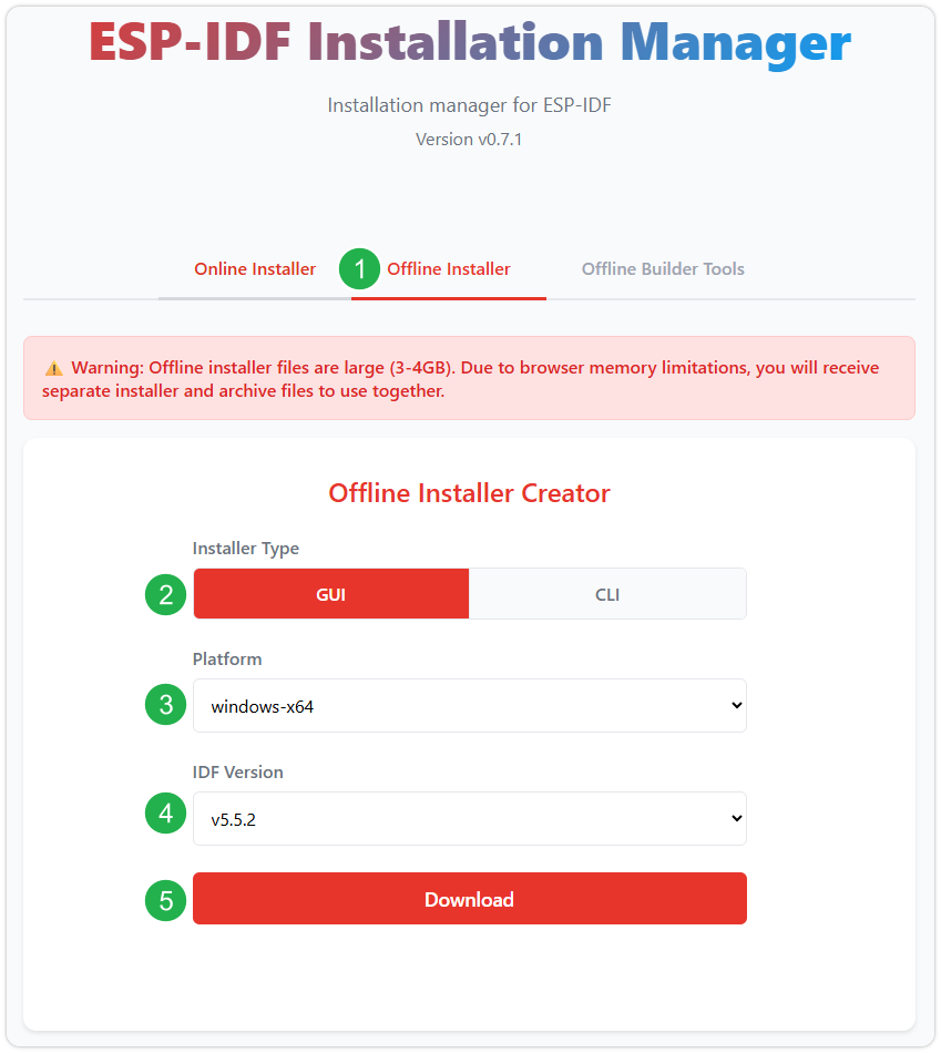
After confirming your selection, click the download button. The browser will automatically download two files: the ESP-IDF Offline Package (.zst) and the ESP-IDF Installer (.exe).
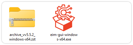
Please wait for both files to finish downloading.
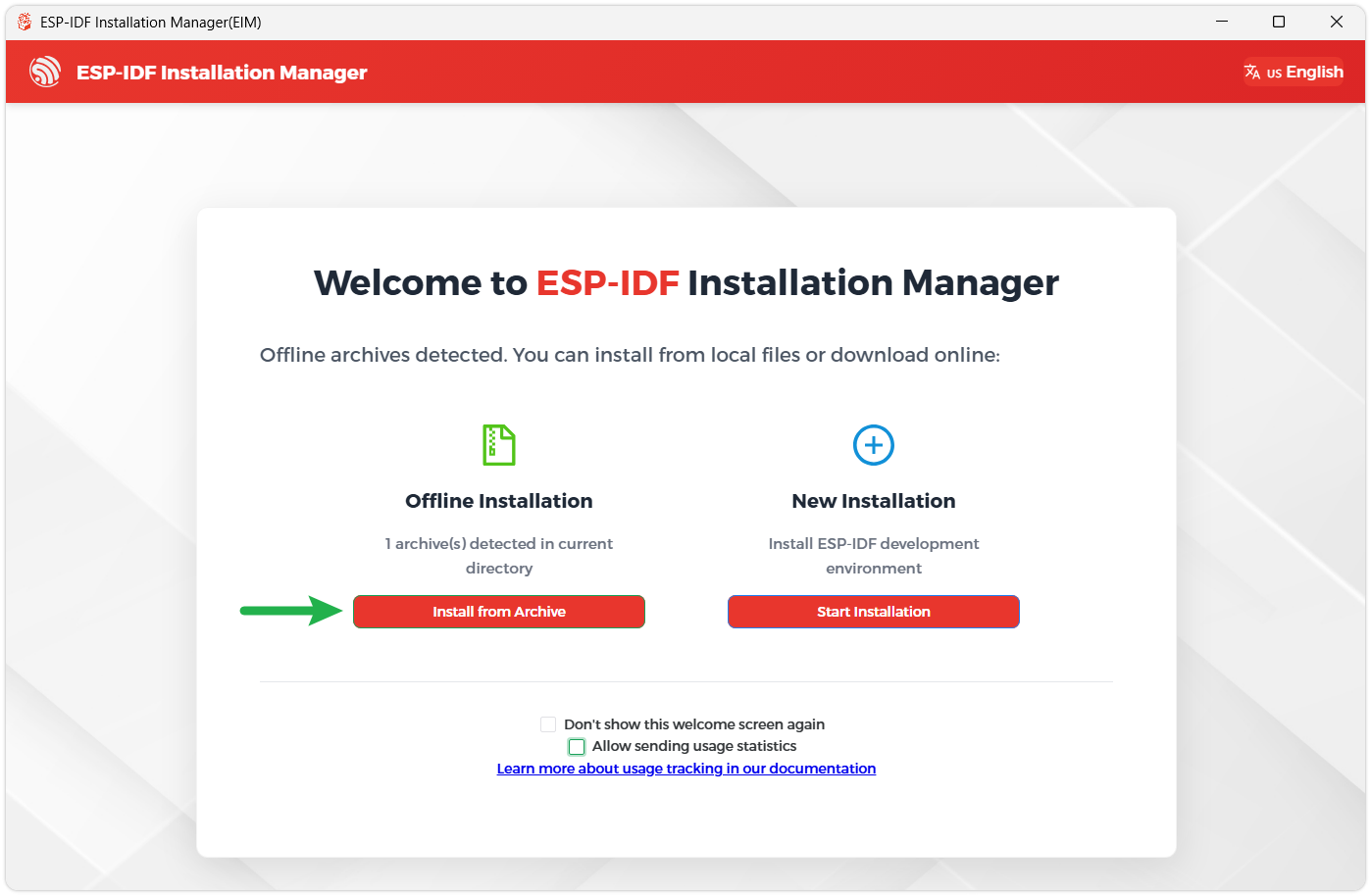
Once the download is complete, double-click to run the ESP-IDF Installer (eim-gui-windows-x64.exe).
The installer will automatically detect if the offline package exists in the same directory. Click Install from archive.
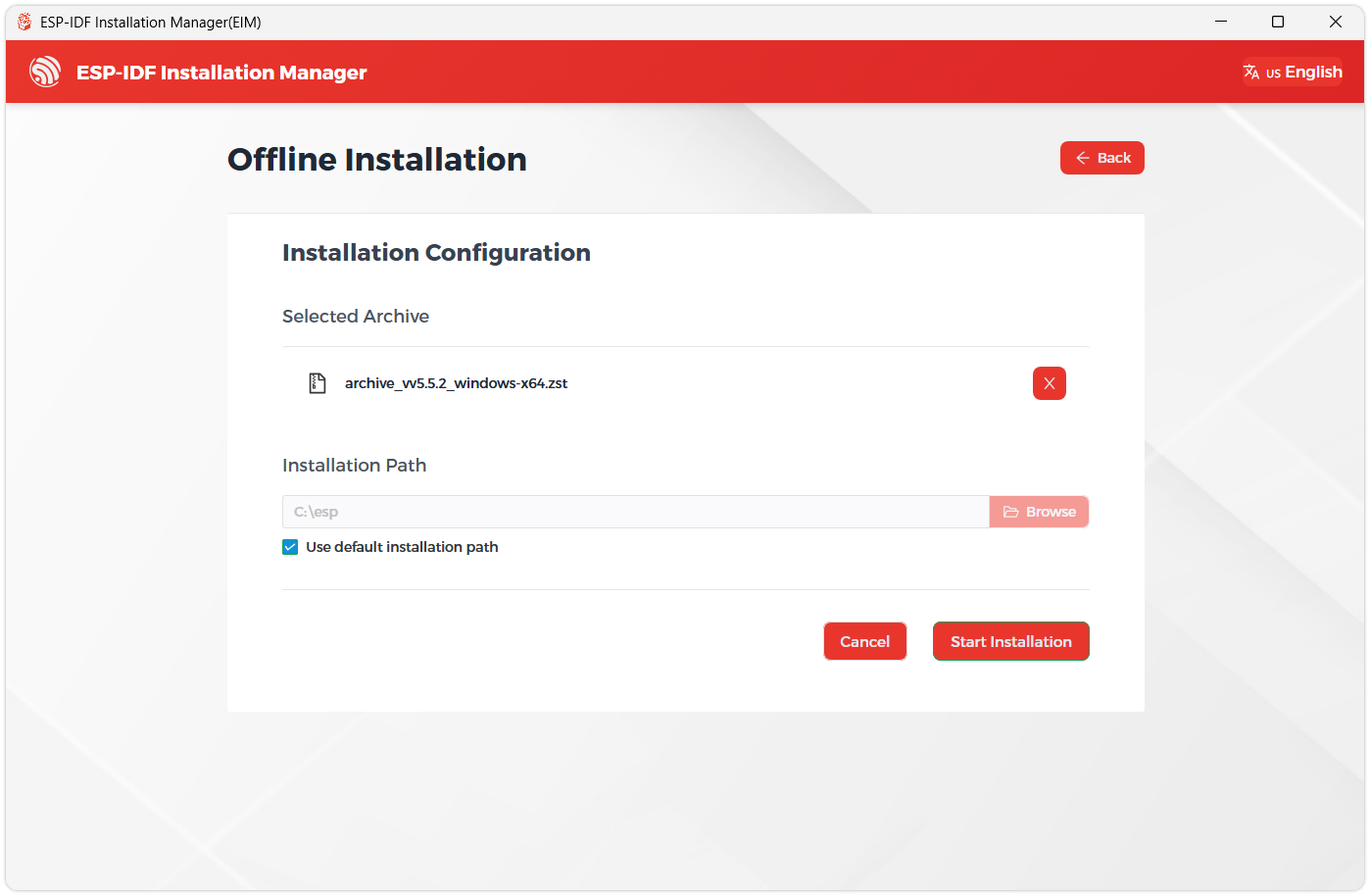
Next, select the installation path. We recommend using the default path. If you need to customize it, ensure the path does not contain Chinese characters or spaces. Click Start installation to proceed.
When you see the following screen, the ESP-IDF installation is successful.
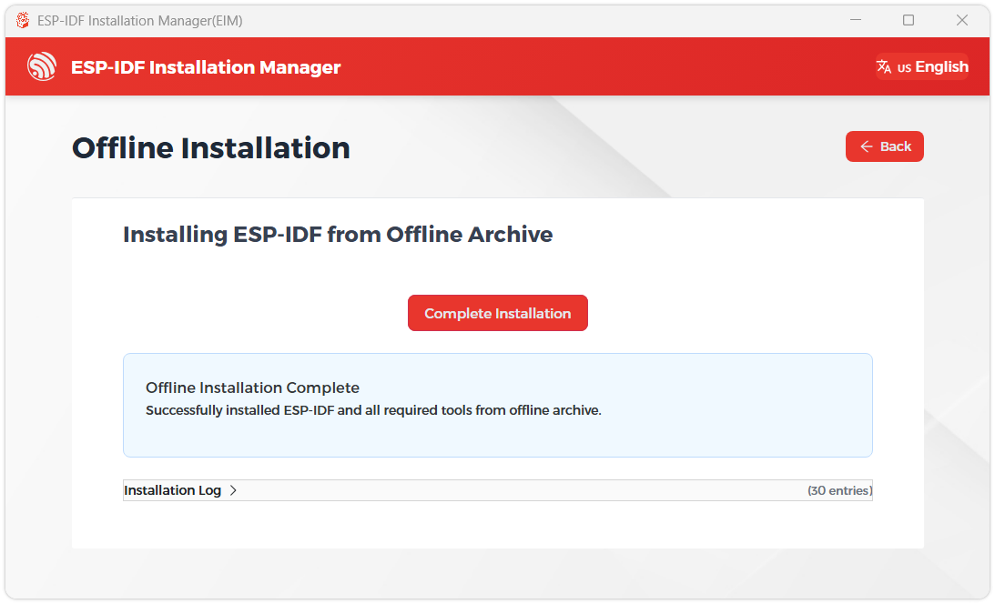
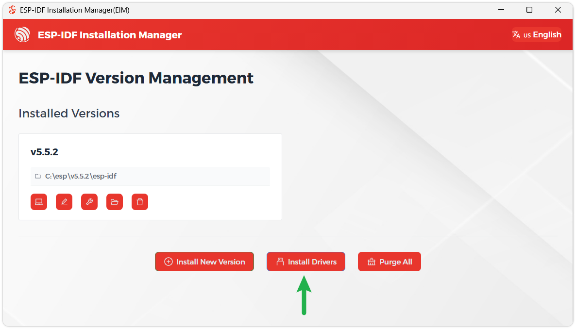
We recommend installing the drivers as well. Click Finish installation, then select Install driver.
Install Visual Studio Code and the ESP-IDF Extension
Download and install Visual Studio Code.
During installation, it is recommended to check Add "Open with Code" action to Windows Explorer file context menu to facilitate opening project folders quickly.
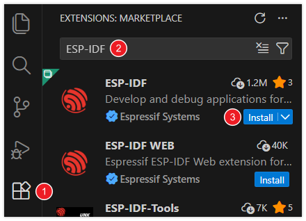
In VS Code, click the Extensions icon
 in the Activity Bar on the side (or use the shortcut Ctrl + Shift + X) to open the Extensions view.
Enter ESP-IDF in the search box, locate the ESP-IDF extension, and click Install.
For ESP-IDF extension versions ≥ 2.0, the extension will automatically detect and recognize the ESP-IDF environment installed in the previous steps, requiring no manual configuration.
Example
Transparent_Test
Example Description
- This example uses the ESP32-C5-Pico-M to drive a 128 × 64 SSD1312 OLED via a 4-wire SPI interface. The project's current target chip is
esp32c5, and thesdkconfigis generated by ESP-IDF 6.0.2. - The driver uses SPI2, operating in SPI mode 0 with a clock frequency of 4 MHz. The screen only receives data, so MISO does not need to be connected.
- The SSD1312 driver provides display interfaces for clearing the screen, refreshing, pixels, lines, rectangles, circles, English characters, Chinese dot-matrix characters, and BMP dot-matrix images. The framebuffer is organized as 128 columns × 8 pages, with each page corresponding to 8 rows of pixels.
- By default,
oled_demo_run()runs, demonstrating in sequence an English string, Chinese dot-matrix characters, a BMP dot-matrix image, a line art scene, and a gauge dot-matrix image. The project also provides a rotating wireframe cube example, which can be switched inmain/main.c.
Hardware Connection
The OLED operating voltage is 3.3 V. Do not connect VCC to a 5 V power supply.
| 0.96inch Transparent OLED | ESP32-C5-Pico-M |
|---|---|
| VCC | 3.3 V |
| GND | GND |
| DIN | GPIO8 |
| CLK | GPIO7 |
| CS | GPIO9 |
| DC | GPIO10 |
| RST | GPIO11 |
| EN | Not connected |
The module's EN pin is enabled by default, and this example does not use it. After wiring, connect the ESP32-C5-Pico-M to the computer via a USB data cable.
This example is written for the module's default 4-wire SPI interface. If the module's solder pads have been switched to the I2C interface, you need to restore it to 4-wire SPI first, or modify the interface configuration and pin definitions in main/BSP/OLED/ssd1312.h and rebuild.
Code Analysis
app_main(): Callsoled_init()to initialize the screen. On successful initialization, it runs the currently selected example program; on failure, it outputs an error code and stops execution.oled_init(): Configures GPIO and the SPI2 bus, resets the OLED, sends SSD1312 initialization commands, clears the framebuffer, and then turns on the display.oled_refresh(): Writes the 128 × 64 frame buffer to the OLED in 8 pages. In SPI mode, each page uses one 128-byte data transfer.oled_demo_run(): Cycles through displaying the English wordWaveshare, the Chinese characters "微雪", a BMP dot-matrix image, a night scene line drawing, and a gauge dot-matrix image.cube_ui_run(): Rotates and perspective-projects the cube's 8 vertices, then draws a continuously rotating wireframe cube using 12 edges.
Both oled_demo_run() and cube_ui_run() contain internally continuous loops, so only one can be selected at a time. In main/main.c, keep the function you want to run and comment out the other:
// cube_ui_run();
oled_demo_run();
To run the rotating cube example, change it to:
cube_ui_run();
// oled_demo_run();
Build and Run
In a terminal with the ESP-IDF 6.0.2 environment initialized, navigate to the example project directory and run the following commands:
idf.py build
idf.py -p COMx flash monitor
Replace COMx with the actual serial port of the ESP32-C5-Pico-M. After flashing is complete, the serial monitor displays the following initialization success message:
SSD1312 initialization successful!
To exit the serial monitor, press Ctrl-].
Expected Behavior
After the default program starts, the OLED cycles through the following displays in order:
| Order | Display Content | Duration |
|---|---|---|
| 1 | English word Waveshare | 2 sec |
| 2 | Chinese characters "微雪" | 2 sec |
| 3 | Built-in 128 × 64 BMP dot-matrix image | 2 sec |
| 4 | Stars, crescent moon, mountain peaks, and pine tree line art | 3 sec |
| 5 | Built-in 128 × 64 gauge dot-matrix image | 5 sec |
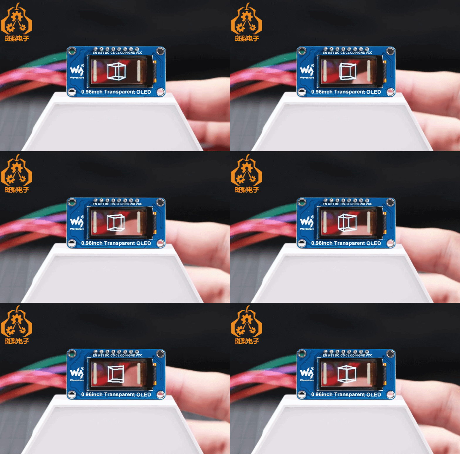
After switching to cube_ui_run(), the OLED continuously displays a wireframe cube rotating around the vertical axis, with the program drawing and refreshing a frame every 20 ms.
STM32
Example
Transparent_Test
Example Description
- This example uses the STM32F103ZET6 to drive a 128 × 64 SSD1312 OLED via a 4-wire SPI interface. The project is based on the STM32Cube HAL and provides a Keil MDK project file.
- The system clock is multiplied from an 8 MHz external crystal to 72 MHz. The OLED uses SPI1 by default, operating in SPI mode 0 with a clock frequency of 2.25 MHz. It only sends data to the screen, so MISO does not need to be connected.
- The SSD1312 driver provides display interfaces for clearing the screen, refreshing, pixels, lines, rectangles, circles, English characters, Chinese dot-matrix characters, and BMP dot-matrix images. The framebuffer size is 1024 bytes, organized as 128 columns × 8 pages, with each page corresponding to 8 rows of pixels.
- By default,
OLED_DemoRun()runs, demonstrating in sequence an English string, Chinese dot-matrix characters, a BMP dot-matrix image, a line art scene, and a gauge dot-matrix image. The project also provides a rotating wireframe cube example, which can be switched inCore/Src/main.c. - The project also reserves an I2C1 driver, with a speed of 400 kHz and a default 7-bit address of
0x3C. The module must be switched to I2C mode via solder pads before using this interface.
Hardware Connection
The OLED operating voltage is 3.3 V. Do not connect VCC to a 5 V power supply.
The default 4-wire SPI wiring is as follows:
| 0.96inch Transparent OLED | STM32F103ZET6 |
|---|---|
| VCC | 3.3 V |
| GND | GND |
| DIN | PA7 / SPI1_MOSI |
| CLK | PA5 / SPI1_SCK |
| CS | PA4 |
| DC | PA3 |
| RST | PA2 |
| EN | Not connected |
The module's EN pin is enabled by default, and this example does not use it. The OLED only receives SPI data, so MISO does not need to be connected. After wiring, connect the ST-Link to the board's SWD interface, where SWDIO corresponds to PA13 and SWCLK corresponds to PA14, and also connect 3.3 V and GND.
To use I2C, first switch the OLED module's hardware interface solder pads to I2C, then wire according to the table below:
| 0.96inch Transparent OLED | STM32F103ZET6 |
|---|---|
| VCC | 3.3 V |
| GND | GND |
| DIN / SDA | PB7 / I2C1_SDA |
| CLK / SCL | PB6 / I2C1_SCL |
| RST | PA2 |
| EN | Not connected |
Also modify App/Inc/oled_config.h to ensure only one communication interface is enabled:
#define OLED_USE_SPI 0
#define OLED_USE_I2C 1
The I2C SCL and SDA require pull-up resistors; if the module does not have integrated pull-up resistors, external appropriate pull-up resistors are needed.
Code Analysis
main(): Initializes HAL, the 72 MHz system clock, GPIO, SPI1, and I2C1, then callsOLED_Init()to initialize the screen. On initialization failure, it entersError_Handler(); on success, it runs the currently selected example program.OLED_Init(): Performs a hardware reset of the OLED via PA2, sends SSD1312 initialization commands, clears the framebuffer, and turns on the display.OLED_Show(): Writes the 128 × 64 framebuffer to the OLED in 8 pages, transmitting 128 bytes of display data per page.OLED_Pixel(),OLED_Line(),OLED_Rect(), andOLED_Circle(): Draw basic graphics in the framebuffer; the screen is only updated after callingOLED_Show().OLED_ShowString(),OLED_DrawChinese(), andOLED_DrawBitmap(): Used to display English strings, Chinese dot-matrix characters, and BMP dot-matrix images, respectively.OLED_DemoRun(): Cycles through displaying the English wordWaveshare, Chinese "微雪", a BMP dot-matrix image, a night scene line drawing, and a gauge dot-matrix image.Cube_DemoRun(): Rotates and perspective-projects the cube's 8 vertices, then draws a continuously rotating wireframe cube using 12 edges.
Both OLED_DemoRun() and Cube_DemoRun() contain internally continuous loops, so only one can be selected at a time. In Core/Src/main.c, keep the function you want to run and comment out the other:
OLED_DemoRun();
/* Cube_DemoRun(); */
To run the rotating cube example, change it to:
/* OLED_DemoRun(); */
Cube_DemoRun();
Build and Run
- Install Keil MDK 5, and install
Keil::STM32F1xx_DFP2.3.0 or a newer version in the Pack Installer. The project is currently configured to use Arm Compiler 5. - Open
MDK-ARM/Transparent_STM32F103ZE.uvprojx. - Click Build or press
F7to compile the project.Transparent_STM32F103ZE.hexwill be generated in theMDK-ARM/Objectsdirectory. - In Options for Target → Debug, select ST-Link Debugger, then click Download to flash the program to the board.
- After flashing is complete, reset or power cycle the board, and the OLED will start running the example program.
The project is configured for an 8 MHz external crystal by default. If the board uses a crystal with a different frequency, modify SystemClock_Config() in Core/Src/main.c accordingly.
Expected Behavior
After the default program starts, the OLED cycles through the following displays in order:
| Order | Display Content | Duration |
|---|---|---|
| 1 | English word Waveshare | 2 sec |
| 2 | Chinese characters "微雪" | 2 sec |
| 3 | Built-in 128 × 64 BMP dot-matrix image | 2 sec |
| 4 | Stars, crescent moon, mountain peaks, and pine tree line art | 3 sec |
| 5 | Built-in 128 × 64 gauge dot-matrix image | 5 sec |
After switching to Cube_DemoRun(), the OLED continuously displays a wireframe cube rotating around the vertical axis, with the program drawing and refreshing a frame every 20 ms.
RP2350
This chapter includes the following sections. Please read as needed:
MicroPython Getting Started Tutorial
New to ESP32 MicroPython development and looking for a quick start? We have prepared a comprehensive ESP32 MicroPython Getting Started Tutorial for you.
- Section 1: Setup Development Environment
- Section 2: Basics
- Section 3: GPIO Digital Output/Input
- Section 4: ADC Analog Input
- Section 5: PWM Output
- Section 6: UART Communication
- Section 7: I2C Communication
- Section 8: SPI Communication
- Section 9: Wi-Fi Basic
- Section 10: Web Server
- Section 11: Bluetooth
- Section 12: Comprehensive Project
Note: This tutorial uses the ESP32-S3-Zero as a teaching example, and all hardware code is based on its pinout. Before proceeding, we recommend checking the pinout diagram of your specific development board to ensure the pin configuration is correct.
Pico Quick Start
Get MicroPython Firmware
Get the onboard MicroPython firmware for the RP2350 PLUS.

Install Thonny IDE
- Please refer to the MicroPython Development Environment Setup Guide to install Thonny IDE.
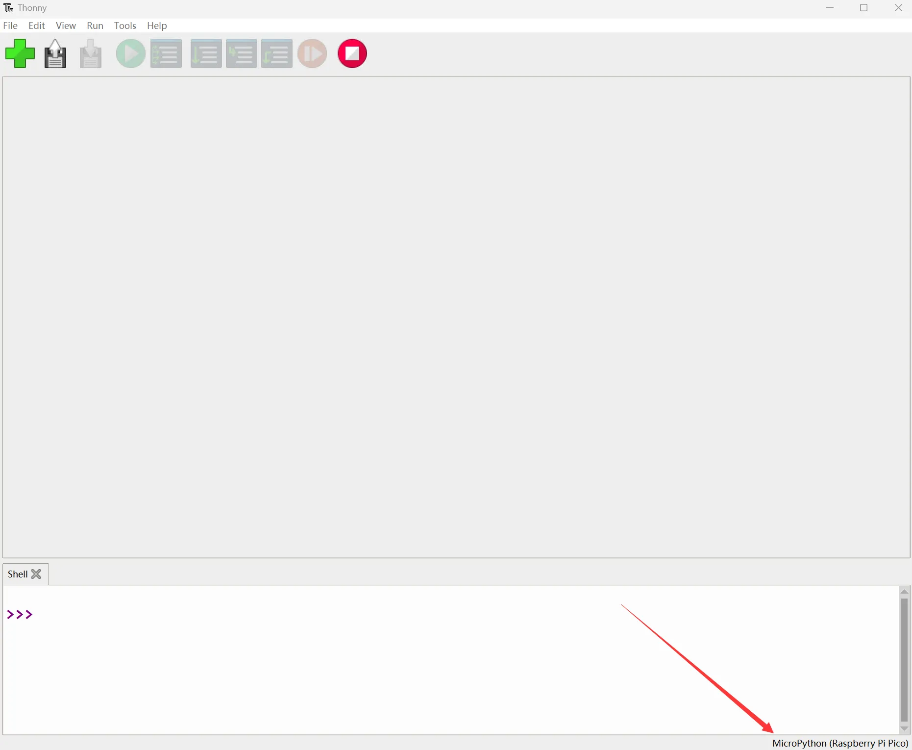
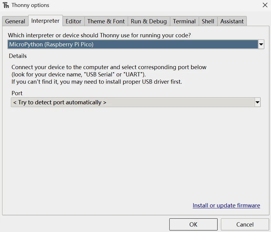
After installation, you need to configure the language and board environment for the first time. Since we are using Pico/Pico2, make sure to select the Raspberry Pi option for the board environment.
Example
Transparent_Test
Example Description
- This example uses the RP2350 PLUS and MicroPython to drive a 128 × 64 SSD1312 OLED. The project uses 4-wire SPI by default, and also supports switching the OLED module to an I2C interface.
- SPI uses SPI1 by default, operating in SPI mode 0 with a clock frequency of 4 MHz. The OLED only receives data, so MISO does not need to be connected.
- I2C uses I2C0 by default, with a clock frequency of 400 kHz and a 7-bit address of
0x3C. The hardware interface selection of the module must match theBUSconfiguration inconfig.py. - The driver class inherits MicroPython's
framebuf.FrameBuffer, uses a 1024-byte framebuffer to store a 128 × 64 monochrome image, and provides interfaces for clearing the screen, refreshing, drawing points, lines, rectangles, text, contrast, color inversion, and display on/off control. - By default, it runs the OLED comprehensive example, displaying in sequence a title page, Chinese "微雪", a product info image, a night scene line art, and a dashboard. The project also provides a continuously rotating wireframe cube example, which can be switched in
config.py.
Project File Description:
| File | Description |
|---|---|
main.py | Program entry; creates an SPI or I2C display object based on the configuration, and starts the selected example |
config.py | Communication interface, pins, speed, I2C address, and example program configuration |
ssd1312.py | SSD1312 initialization, SPI/I2C communication, framebuffer refresh, and display control |
demo.py | OLED comprehensive example, including text, graphics, and dot-matrix content |
cube.py | Rotating wireframe cube example |
glyphs.py | 32 × 41 monochrome dot-matrix data and drawing functions for Chinese "微雪" |
Hardware Connection
The OLED operating voltage is 3.3 V. Do not connect VCC to a 5 V power supply.
The project is configured for 4-wire SPI by default. Wire according to the table below:
| 0.96inch Transparent OLED | RP2350 PLUS |
|---|---|
| VCC | 3.3 V |
| GND | GND |
| DIN | GP11 / SPI1 TX |
| CLK | GP10 / SPI1 SCK |
| CS | GP9 |
| DC | GP8 |
| RST | GP12 |
| EN | Not connected |
The module's EN pin is enabled by default, and this example does not use it. After wiring, connect the RP2350 PLUS to the computer using a USB cable that supports data transfer.
To use I2C, first switch the interface selection solder pad on the back of the OLED module to I2C, then wire according to the table below:
| 0.96inch Transparent OLED | RP2350 PLUS |
|---|---|
| VCC | 3.3 V |
| GND | GND |
| DIN / SDA | GP4 / I2C0 SDA |
| CLK / SCL | GP5 / I2C0 SCL |
| RST | GP12 |
| CS | Not connected |
| DC | Not connected |
| EN | Not connected |
Also change the communication interface in config.py to:
BUS = "I2C"
The I2C SDA and SCL require pull-up resistors; if the module does not have integrated pull-up resistors, external appropriate pull-up resistors are needed.
Code Analysis
create_display(): ReadsBUSfromconfig.py, and creates anSSD1312_SPIorSSD1312_I2Cobject based on the configuration; throws an exception if the configuration value is notSPIorI2C.SSD1312._initialize(): First performs a hardware reset of the OLED via GP12, then sends SSD1312 initialization commands, clears the framebuffer, and turns on the display.SSD1312.show(): Writes the 128 × 64 framebuffer to the OLED in 8 pages, transmitting 128 bytes of display data per page.demo.run(): Cycles through drawing a title page, Chinese dot-matrix, product info image, night scene line art, and dashboard, and callsshow()to refresh the screen after each drawing.glyphs.draw_text(): Parses 32 × 41 monochrome dot-matrix data bit by bit, used to display Chinese "微雪".cube.run(): Rotates and perspective-projects the cube's 8 vertices, then connects 12 edges, drawing and refreshing a frame approximately every 20 ms.
In config.py, select the example program via DEMO:
# OLED comprehensive example
DEMO = "oled"

# Rotating wireframe cube example
# DEMO = "cube"
Both demo.run() and cube.run() are continuously running loops, so only one example can be run at a time.
Run the Example
- Install the applicable MicroPython firmware for the RP2350 PLUS, then open Thonny.
- In Thonny, select the MicroPython (Raspberry Pi Pico) interpreter, and select the serial port corresponding to the board.
- Upload
main.py,config.py,ssd1312.py,demo.py,cube.pyandglyphs.pyall to the root directory of the board's file system. - Reset the board or run
main.pyin Thonny. After successful initialization, the Shell outputs:
SSD1312 initialized using SPI
When using I2C, SPI in the output will change to I2C. When uploading files, keep the original file names. main.py will execute automatically after the board boots.
Expected Behavior
After setting DEMO to "oled" by default, the OLED cycles through the following displays in order:
| Order | Display Content | Duration |
|---|---|---|
| 1 | WAVESHARE, RP2350 and SSD1312 OLED title page | 2 sec |
| 2 | Chinese "微雪" dot-matrix | 2 sec |
| 3 | 0.96 OLED 128x64 product info image | 2 sec |
| 4 | Stars, crescent moon, mountain peaks, and pine tree line art | 3 sec |
| 5 | Dashboard composed of RP2350, interface status, battery icon, and line chart | 5 sec |
After setting DEMO to "cube", the OLED continuously displays a wireframe cube rotating around the vertical axis, with the program refreshing a frame approximately every 20 ms.
Resources
1. Examples
2. Hardware Resources
3. Software Tools
4. Other Resources
Support
Monday-Friday (9:30-6:30) Saturday (9:30-5:30)
Email: services01@spotpear.com