- sales/support
Google Chat:---
- sales
+86-0755-88291180
- sales01
sales@spotpear.com
- sales02
dragon_manager@163.com
- support
tech-support@spotpear.com
- CEO-Complaints
zhoujie@spotpear.com
- Only Tech-Support
WhatsApp:13246739196
- Purchase/Shipping/Refund
WhatsApp:13424403025
- HOME
- >
- ARTICLES
- >
- Common Moudle
- >
- ESP
ESP32-P4-WIFI6-Touch-LCD-7 User Guide
Features
- Processor
- Equipped with a RISC-V 32-bit dual-core processor (HP system), featuring DSP and ISA extensions, a Floating-Point Unit (FPU), with a main frequency of up to 360 MHz.
- Equipped with a RISC-V 32-bit single-core processor (LP system), with a main frequency of up to 40 MHz.
- Equipped with an ESP32-C6 WIFI/BT co-processor, expanding WIFI 6/Bluetooth 5 and other functions through SDIO
- Memory
- 128 KB of high-performance (HP) system read-only memory (ROM).
- 16 KB of low-power (LP) system read-only memory (ROM).
- 768 KB of high-performance (HP) L2 memory (L2MEM).
- 32 KB of low-power (LP) SRAM.
- 8 KB of system tightly coupled memory (TCM).
- Stacked 32MB PSRAM within the chip package, and externally integrated 32MB Nor Flash.
- Peripheral Interfaces
- Onboard peripherals including MIPI-CSI, MIPI-DSI, USB 2.0 OTG, an SDIO 3.0 TF card slot, dual microphones (supports echo cancellation), and speaker, etc.
Hardware Description
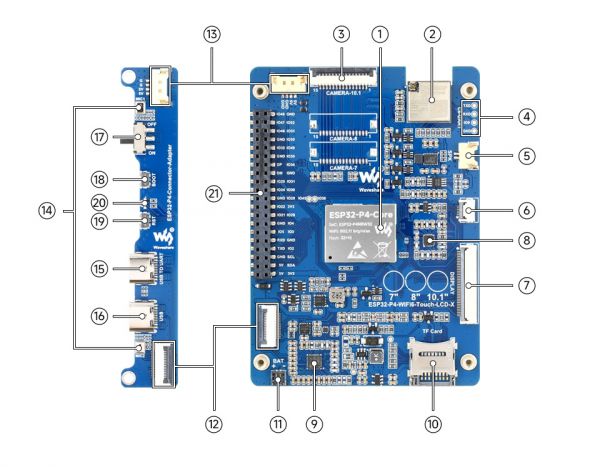
- ESP32-P4-Core Integrates ESP32-P4NRW32 and 32MB Nor Flash
- ESP32-C6-MINI-1U-H8 module SDIO interface protocol, extending Wi-Fi 6 / Bluetooth 5 (LE)
- MIPI CSI interface 15PIN pitch 1.0mm interface for connecting MIPI-2lane camera
- 2.54mm 4PIN pads Used for ESP32-C6 module firmware flashing
- Speaker header 1.25mm 2PIN
- Touch panel connector Supports touch function expansion
- DSI display connector Used for connecting display devices and data transmission
- ES8311 low-power audio codec chip Handles audio encoding and decoding tasks
- ES7210 Echo cancellation algorithm chip Effectively eliminates echo and improves audio capture accuracy
- TF card slot Utilizes the SDIO 3.0 interface protocol, supporting storage expansion
- Battery header A JST 2Pin connector with 1.2mm pitch, suitable for external battery power supply
- Board-to-Board signal transmission interfaces Designed for a 16Pin 0.5mm pitch FPC cable, enabling signal communication between boards
- Board-to-Board power supply & common ground interfaces Designed for an ultra-thin 1.25mm 4Pin header cable, ensuring stable power and common ground connection
- Onboard microphones Features a dual-microphone array design, optimizing audio capture performance
- USB TO UART Type-C port Provides power supply, firmware flashing, and debugging capabilities
- USB OTG Type-C port A USB OTG 2.0 High-Speed interface supporting peripheral expansion
- Power supply ON/OFF switch Controls the device's power on/off state.
- BOOT button Presses it when powering on or resetting to enter download mode
- RESET button Used for device reset operations
- PWR & Charge dual-color indicator Serve as a power indicator and a charging indicator, visually displaying device status
- 40PIN header Provides a general-purpose expansion interface, supporting connection of various peripherals and function expansion
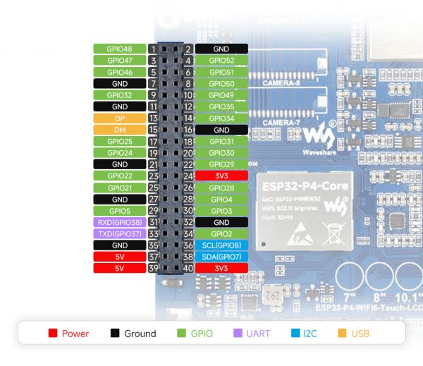
Pinout Definition
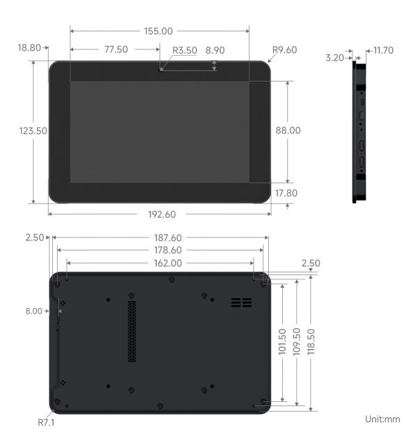
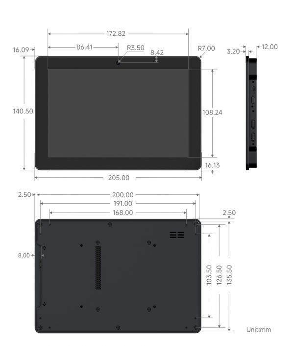
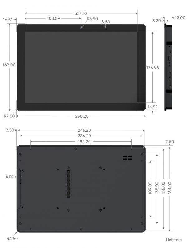
Dimensions
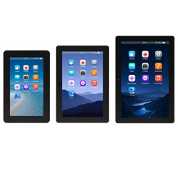
ESP32-P4-WIFI6-Touch-LCD-7
ESP32-P4-WIFI6-Touch-LCD-8
ESP32-P4-WIFI6-Touch-LCD-10.1
Working with ESP-IDF
This chapter includes the following sections, please read as needed:
Setting up the Development Environment
For the ESP32-P4-WIFI6-Touch-LCD development board, it is recommended to use ESP-IDF V5.5.0 or higher.
The following guide uses Windows as an example, demonstrating development using VS Code + the ESP-IDF extension. macOS and Linux users should refer to the official documentation.
Install the ESP-IDF Development Environment
Download the installation manager from the ESP-IDF Installation Manager page. This is Espressif's latest cross-platform installer. The following steps demonstrate how to use its offline installation feature.
Click the Offline Installer tab on the page, then select Windows as the operating system and choose your desired version from the filter bar.
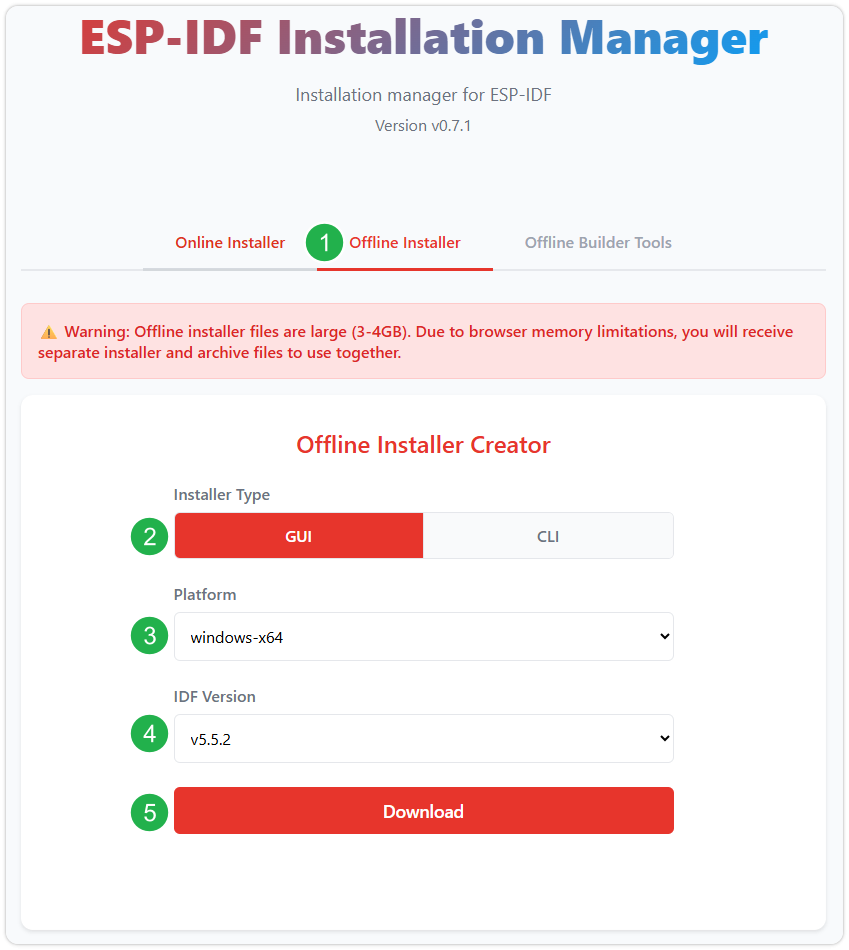
After confirming your selection, click the download button. The browser will automatically download two files: the ESP-IDF Offline Package (.zst) and the ESP-IDF Installer (.exe).
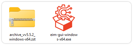
Please wait for both files to finish downloading.
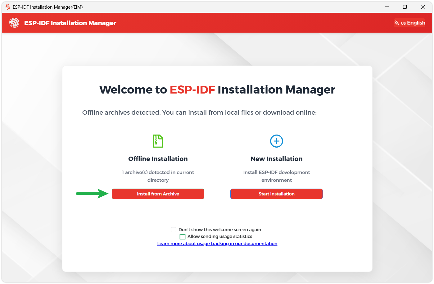
Once the download is complete, double-click to run the ESP-IDF Installer (eim-gui-windows-x64.exe).
The installer will automatically detect if the offline package exists in the same directory. Click Install from archive.
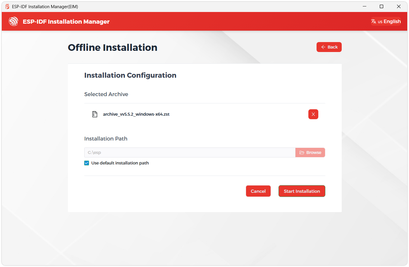
Next, select the installation path. We recommend using the default path. If you need to customize it, ensure the path does not contain Chinese characters or spaces. Click Start installation to proceed.
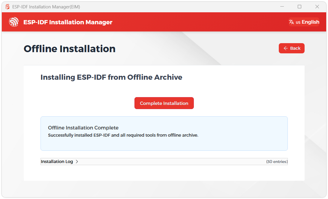
When you see the following screen, the ESP-IDF installation is successful.
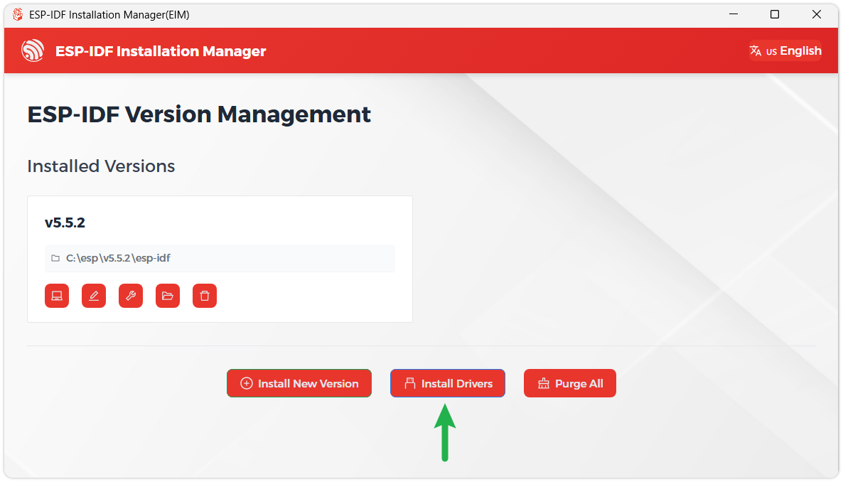
We recommend installing the drivers as well. Click Finish installation, then select Install driver.
Install Visual Studio Code and the ESP-IDF Extension
Download and install Visual Studio Code.
During installation, it is recommended to check Add "Open with Code" action to Windows Explorer file context menu to facilitate opening project folders quickly.
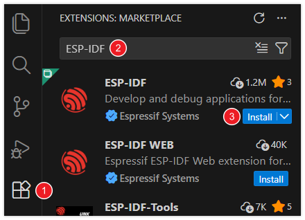
In VS Code, click the Extensions icon in the Activity Bar on the side (or use the shortcut Ctrl + Shift + X) to open the Extensions view.
Enter ESP-IDF in the search box, locate the ESP-IDF extension, and click Install.
For ESP-IDF extension versions ≥ 2.0, the extension will automatically detect and recognize the ESP-IDF environment installed in the previous steps, requiring no manual configuration.
Demo
This Wiki keeps updating the ESP32-P4 demos, some demos require ESP-IDF version dependencies, it will take a period of time to test the update, please be patient.
The best way to learn a language or development environment is to start from the basics. This section will provide a detailed guide on how to create projects, develop from existing projects, and include embedded classic tutorials such as HelloWorld and the usage of common port I2C.
1. Introduction to Basic Structure of ESP-IDF Project
Project Structure:
Open the ESP-IDF plugin, click New project, select the ESP-IDF demo -- > sample_project -- > click Create
Create a new project and open it in the window, you can see the structure of VSCode as follows:
├── CMakeLists.txt
├── main
│   ├── CMakeLists.txt
│   └── main.c
└── README.md
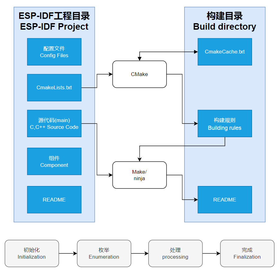
ESP-IDF Project Details:
Component: The components in ESP-IDF are the basic modules for building applications, each component is usually a relatively independent code base or library, which can implement specific functions or services, and can be reused by applications or other components, similar to the definition of libraries in Python development.
Component reference: The import of libraries in the Python development environment only requires to "import library name or path", while ESP-IDF is based on the C language, and the importing of libraries is configured and defined through CMakeLists.txt.
When we use online components, we usually use
idf.py add-dependency <componetsName>to add online components to the project, which generates anidf_component.ymlfile for managing components.The purpose of CmakeLists.txt: When compiling ESP-IDF, the build tool CMake first reads the content of the top-level CMakeLists.txt in the project directory to read the build rules and identify the content to be compiled. When the required components and demos are imported into the CMakeLists.txt, the compilation tool CMake will import everything that needs to be compiled according to the index. The compilation process is as follows:
Description of Bottom Toolbar of VS Code User Interface:
When opening an ESP-IDF project, the environment will be loaded automatically at the bottom. For the development of ESP32-P4, the bottom toolbar is very important, as shown in the figure:
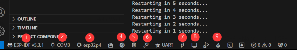
- ①. ESP-IDF Development Environment Version Manager: When our project requires differentiation of development environment versions, it can be managed by installing different versions of ESP-IDF. When the project uses a specific version, it can be switched to by utilizing it
- ②. Device flashing COM port: Select to flash the compiled program into the chip
- ③. Select set-target chip model: Select the corresponding chip model, for example, ESP32-P4 needs to choose esp32p4 as the target chip
- ④. menuconfig: Click it to modify sdkconfig configuration file
- ⑤. fullclean button: When the project compilation error or other operations pollute the compiled content, you can clean up all the compiled content by clicking it
- ⑥. Build project: When a project satisfies the build, click this button to compile
- ⑦. flash button: When a project build is completed, select the COM port of the corresponding development board, and click this button to flash the compiled firmware to the chip
- ⑧. monitor enable flashing port monitoring: When a project passes through Build --> Flash, click this button to view the log of output from flashing port and debugging port, so as to observe whether the application works normally
- ⑨.Build Flash Monitor one-click button: Which is used to continuously execute Build->Flash->Monitor, often referred to as "little flame”
2. Hello World Example
After understanding the description of bottom toolbar of VS Code user interface, the Hello World project allows you to quickly get started and understand the basic projects of the ESP32 development environment. It demonstrates how to use ESP-IDF to create a basic application, and covers the ESP32 development process, including compilation, flashing, and monitor debugging steps.
After opening the sample project
HelloWorld, set the target port and chip type (Note: There is a loading action in the lower right corner when the chip type is selected, indicating that ESP-IDF is executing the commandidf.py set-target esp32p4. It needs to pull the architecture package environment corresponding to the chip from the package manager, which may take some time. Please wait patiently. If you perform build or other operations at this time, there will be errors!!!)By using the bottom tool to build, burn, and monitor with just one click, you can view the terminal output Hello World!
Code content analysis
- There is only one
app_mainmain function in the code, which determines the print content output through conditional judgment, and adds a loop at the end to achieve 10s restart of the chip. app_mainfunction is the entry point for user applications in the ESP-IDF (Espressif IoT Development Framework) development framework. It is the core function of the ESP-IDF project and is equivalent to the main function in the standard program of the C language. In ESP32 development,app_mainfunction is the first task scheduled by the real-time operating system (FreeRTOS), which is the starting point for the execution of the user's code.
- There is only one
3. I2C Example
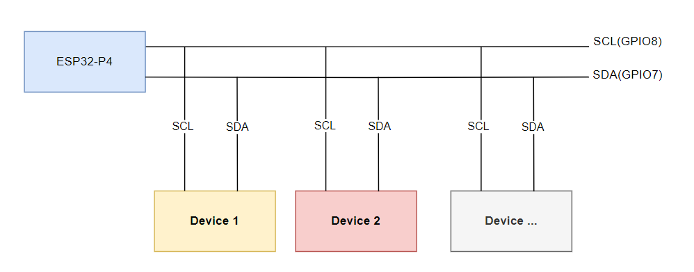
I2C is a commonly used serial communication bus, which can communicate through two lines, one data cable (SDA, Serial Data) and one clock cable (SCL, Serial Clock), and supports multi-master and multi-slave mode. The ESP32-P4 chip features two I2C bus interfaces. Internally, the GPIO switch matrix allows these interfaces to be configured to use any GPIO pin. This flexibility enables users to freely assign any GPIO as I2C pins. Additionally, the ESP32-P4 I2C supports both slave and master modes. The following section focuses on the I2C master mode, which is used by the ESP32-P4 to initiate communication, control, and send data requests to or receive data from slave devices (such as any I2C‑compatible sensor). On the ESP32-P4, the I2C pins are configured by default as SCL(GPIO8) and SDA(GPIO7)
In ESP-IDF, the I2C bus must be configured using the i2c_master_bus_config_t:
i2c_master_bus_config_t::clk_sourceselects the source clock for the I2C bus. To use the default I2C clock source (which is typically recommended), set it to I2C_CLK_SRC_DEFAULT.i2c_master_bus_config_t::i2c_portspecifies the I2C port to be used by the controller. As mentioned earlier, the ESP32-P4 has two I2C interfaces. When two separate I2C buses need to operate simultaneously, this setting is used to distinguish between them.i2c_master_bus_config_t::scl_io_numsets the GPIO number for the Serial Clock (SCL) line. On the ESP32-P4-WIFI6-Touch-LCD-X, this is 8.i2c_master_bus_config_t::sda_io_numsets the GPIO number for the Serial Data (SDA) line. On the ESP32-P4-WIFI6-Touch-LCD-X, this is 7.i2c_master_bus_config_t::glitch_ignore_cntdefines the glitch period threshold for the Master Bus. Glitches on the line shorter than this value will be filtered out. A typical setting is 7.i2c_master_bus_config_t::enable_internal_pullupenables internal pull-up resistors. On the ESP32-P4-WIFI6-Touch-LCD-X, external I2C pull-ups are already provided, so internal pull-ups should not be enabled.
Based on the above, the I2C configuration is defined as follows:
   i2c_master_bus_config_t i2c_bus_config = {
       .clk_source = I2C_CLK_SRC_DEFAULT,
       .i2c_port = I2C_NUM_0,
       .scl_io_num = 8,
       .sda_io_num = 7,
       .glitch_ignore_cnt = 7,
       .flags.enable_internal_pullup = false,
   };
Open the
i2c_toolsproject, select the correct COM port and chip model, then click the button to enter the settings. This will open a new tab: SDK Configuration editor, also known as menuconfig. Directly search for I2C in the search bar. You will see the relevant configuration options, and the SCL GPIO Num and SDA GPIO Num in the example code should already correspond toSCL(GPIO8)andSDA(GPIO7).Next, you can directly compile, flash, and monitor by clicking. After completion, a command menu will appear in the terminal. When you execute the i2cdetect command, it will print all I2C addresses. If a device is present, its address will be displayed as a number (the device at I2C address 0x18 is the onboard ES8311 Codec audio chip, which will be explained in detail in the I2S section), as shown in the figure:
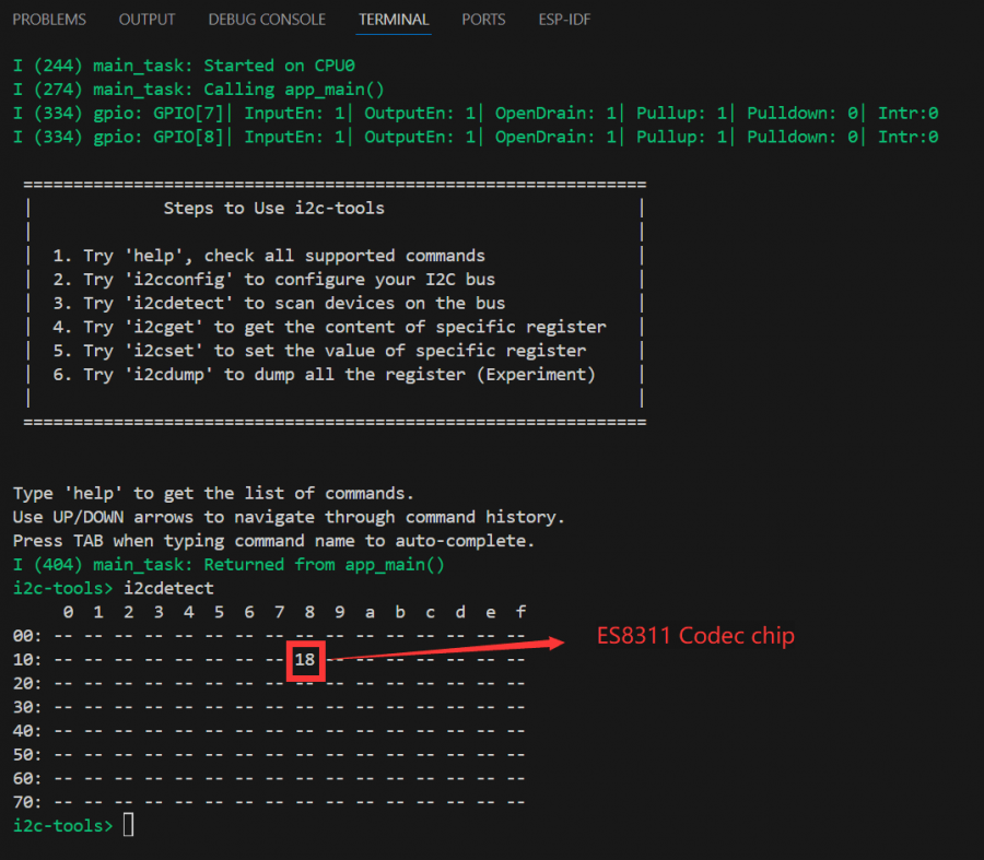
The above steps have established the foundation for I2C device communication. In I2C protocol devices, it is often necessary to write register configurations to the corresponding device address via the I2C bus to enable its functions. This requires writing the I2C device initialization code in the program to drive the device. Different I2C devices have different I2C addresses. During development, we can use the i2ctools utility to scan for connected I2C addresses. Then, by consulting the device's datasheet for register maps and configuration details, we can implement communication over the I2C bus.
4. WIFI Networking Example
The ESP32-P4 itself does not have built-in WIFI/BT functionality. However, the ESP32-P4 expands WIFI capability by connecting to an ESP32-C6 module via SDIO. The ESP32-C6 acts as a Slave and, through a set of command sets, enables the ESP32-P4 as the Host to utilize WIFI 6/BT 5 features over SDIO. After adding the following two components, seamless integration with esp_wifi can be achieved.
// In a WIFI project, add the following two components using the ESP-IDF component management tool
// Depending on the component version, different versions may be required; actual results may vary
idf.py add-dependency espressif/esp_wifi_remote==0.14.*
idf.py add-dependency espressif/esp_hosted==1.4.*
Open the
wifistationproject and proceed to add the required components.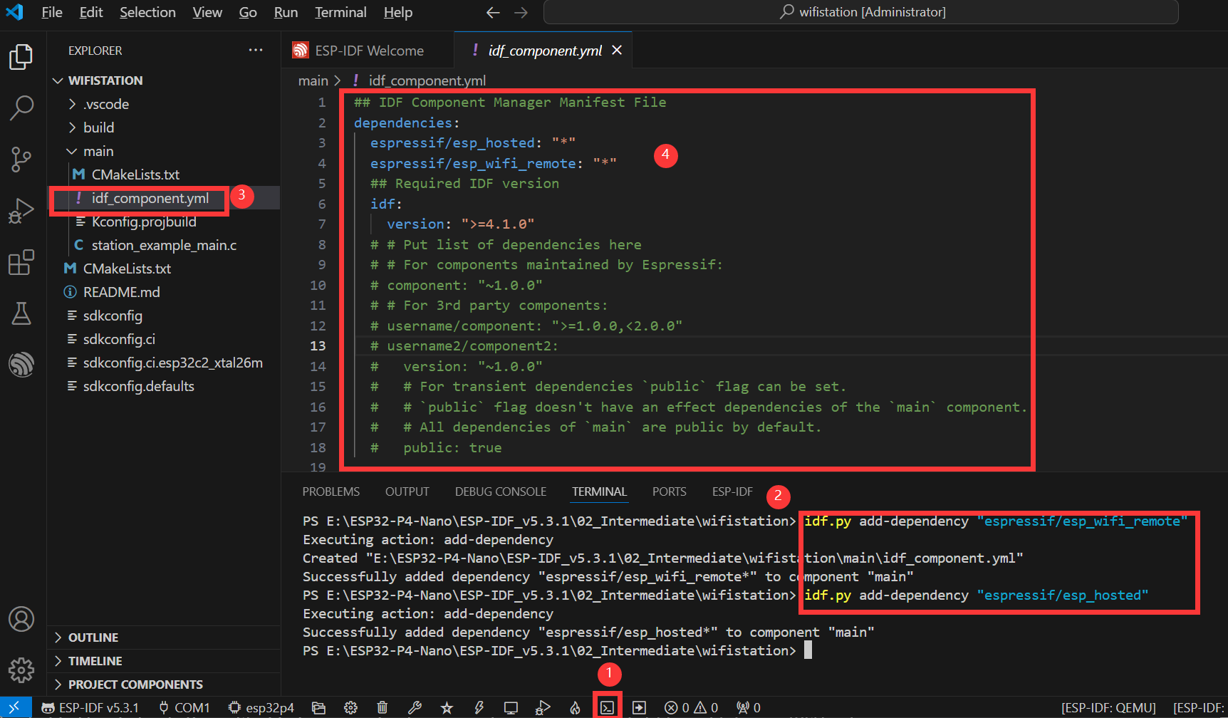
The image above illustrates the specific steps for adding components:
- Open the ESP-IDF Terminal.
- Add the required components in the Terminal.
- After successful addition, an
idf_component.ymlfile will appear in the main folder of the project. As explained in the ESP‑IDF project directory section, this file is used to manage project components. - Opening this file, it can be seen that two components have been added:
espressif/esp_hosted: "1.4.*"andespressif/esp_wifi_remote: "0.14.*". These components will be included in the project during the build process.
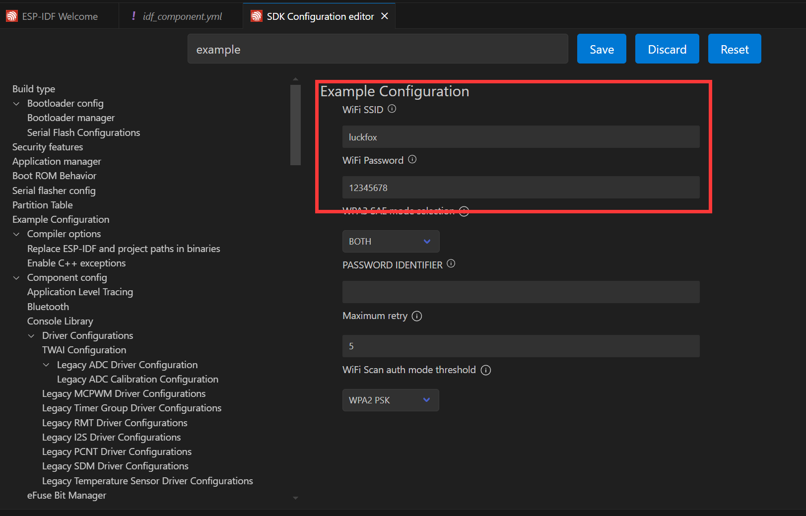
Next, click the button to open the settings. Search for Example and configure the ssid and password of the target Wi‑Fi network. Note: The ESP32‑C6 supports 2.4 GHz Wi‑Fi 6. Make sure to select a Wi‑Fi network operating in the 2.4 GHz band. After modifying the settings, remember to save them; otherwise, errors may occur.
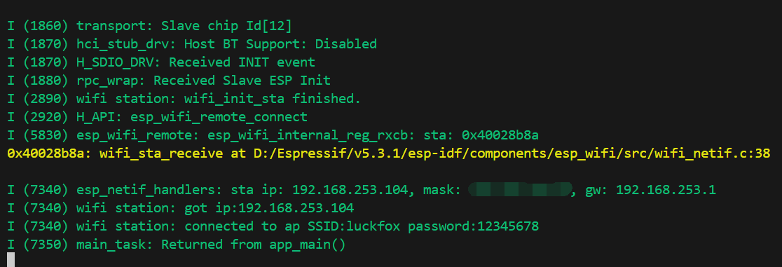
Next, you can directly compile, flash, and monitor by clicking. After completion, the terminal will display the following result, indicating that the ESP32-P4-WIFI6-Touch-LCD-X has successfully connected to the Wi‑Fi network and is online:
5. SDMMC Example
The ESP32-P4 features an onboard 4-Wire SDIO 3.0 card slot for expanding off-chip storage.
Supported Rate Modes
- Default rate (20 MHz)
- High-speed mode (40 MHz)
Configuring Bus Width and Frequency
In ESP-IDF, configuration is set using
sdmmc_host_tandsdmmc_slot_config_t. For example, to set the default 20 MHz communication frequency with a 4‑line bus width, it would be:sdmmc_host_t host = SDMMC_HOST_DEFAULT();
sdmmc_slot_config_t slot_config = SDMMC_SLOT_CONFIG_DEFAULT();In the design that supports 40 MHz communication, you can adjust the max_freq_khz field in the sdmmc_host_t structure to increase the bus frequency:
sdmmc_host_t host = SDMMC_HOST_DEFAULT();
host.max_freq_khz = SDMMC_FREQ_HIGHSPEED;
The SDMMC 4-wire connection on the ESP32-P4 should be defined as:
sdmmc_slot_config_t slot_config = SDMMC_SLOT_CONFIG_DEFAULT();
slot_config.width = 4;
slot_config.clk = 43;
slot_config.cmd = 44;
slot_config.d0 = 39;
slot_config.d1 = 40;
slot_config.d2 = 41;
slot_config.d3 = 42;
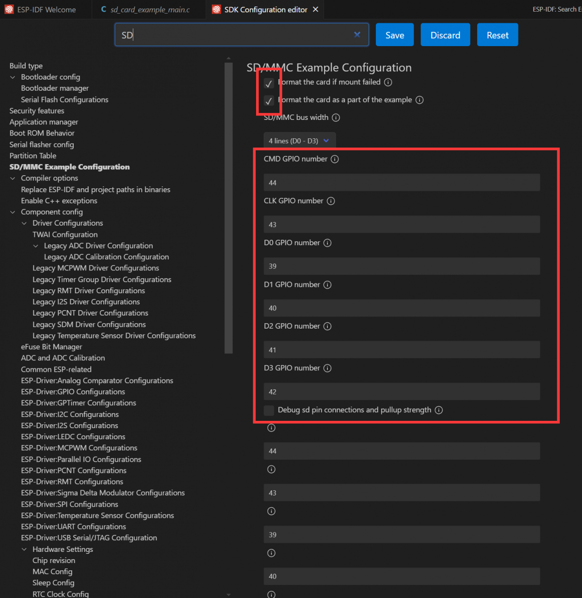
slot_config.flags |= SDMMC_SLOT_FLAG_INTERNAL_PULLUP;Open the SDMMC project, select the appropriate COM port and chip model. Since the demo project defines the pins as macros, they need to be configured here; alternatively, you can directly enter the pin numbers. Click button to enter the settings. This will open a new tab: SDK Configuration editor, also known as menuconfig. In the search bar, type sd to find the relevant configuration. The example settings are already prepared. Enable the option for default initialization and ensure the example file is created by default.
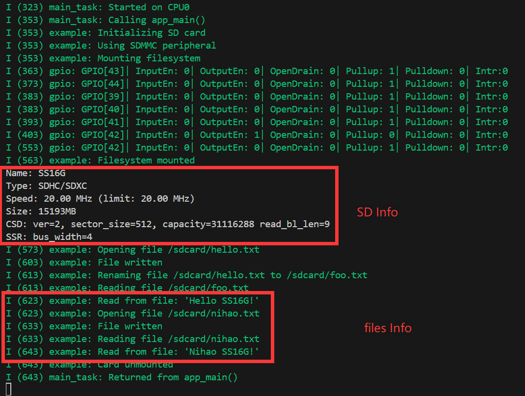
Next, insert the prepared TF card. Click to compile, flash and monitor. After completion, the terminal will display a command menu and list the contents of the directory on the TF card.
6. I2S Audio Example
I2S (Inter-IC Sound) is a digital communication protocol designed for transmitting audio data. I2S is a serial bus interface that is primarily used for digital audio data transmission between audio devices, such as digital audio processors (DSPs), digital-to-analog converters (DACs), analog-to-digital converters (ADCs), and audio codecs. The ESP32-P4 includes one I2S peripheral. By configuring this peripheral with the I2S driver, sampled audio data can be input and output.
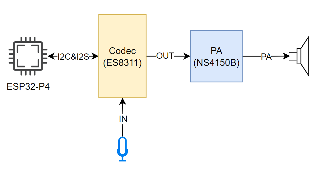
The ESP32-P4 board integrates an ES8311 Codec chip and an NS4150B power amplifier. The I2S bus and pin assignments are as follows:
- MCLK (Master Clock): The master clock signal. The clock is typically provided to the ES8311 by an external device (such as an MCU or DSP), which serves as the clock source for its internal digital audio processing module.
- SCLK (Serial Clock): The serial clock signal. This signal is typically used for clock synchronization for I2S data transmission and is generated by the master device to indicate the rate at which the data is transferred. The transmission of each bit of each audio sample requires a clock cycle.
- ASDOUT (Audio Serial Data Output) or DOUT: The audio data output pin. The ES8311 outputs decoded digital audio data to this pin, which is then transmitted to an amplifier chip or other audio device.
- LRCK (Left/Right Clock) or WS (Word Select): The left/right channel selection signal, indicating whether the current data sample belongs to the left or right channel. Typically in the I2S protocol, one clock cycle represents the left channel data and the other clock cycle represents the right channel data.
- DSDIN (Digital Serial Data Input) or DIN: The digital audio data input pin. This pin receives audio data from an external audio device or a master. The ES8311 decodes this data and processes the audio signals through an internal digital signal processing module.
| Functional Pin | ESP32-P4 Pin |
|---|---|
| MCLK | GPIO13 |
| SCLK | GPIO12 |
| ASDOUT | GPIO11 |
| LRCK | GPIO10 |
| DSDIN | GPIO9 |
| PA_Ctrl (Power amplifier chip enable pin, active high) | GPIO53 |
The ES8311 driver for ESP32-P4 utilizes the ES8311 component, which can be added via the IDF Component Manager:
idf.py add-dependency "espressif/es8311"
Open the
i2scodecproject and proceed to add the required components.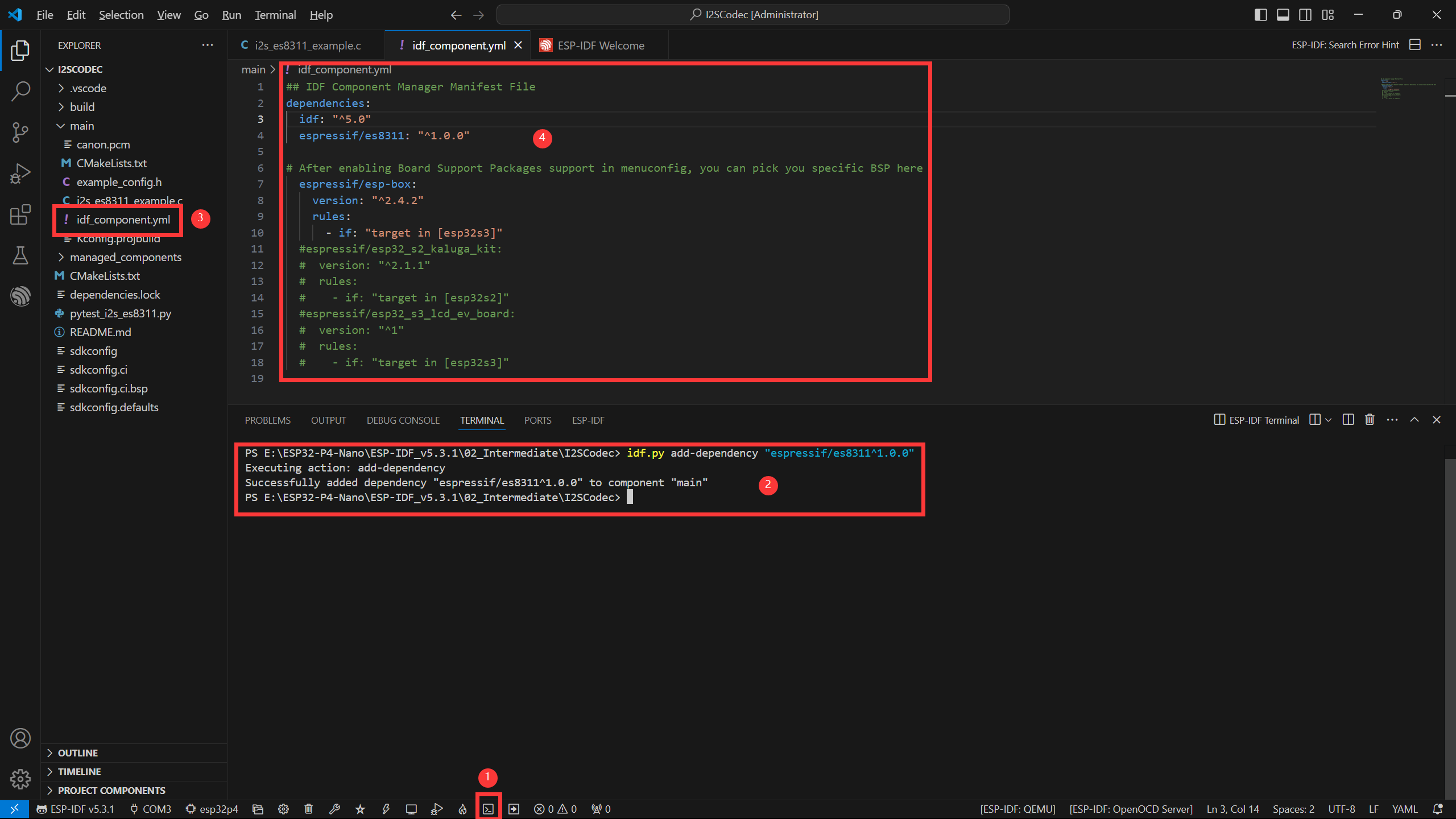
- Open the ESP-IDF Terminal.
- Add the required components in the Terminal.
- After successful addition, an
idf_component.ymlfile will appear in the main folder of the project. As explained in the ESP‑IDF project directory section, this file is used to manage project components. - Once opened, you can see that
espressif/es8311component has been added, and will be included in the project during the build process.
Next, click the button to open the settings, search for Example, and adjust the volume to a suitable level.
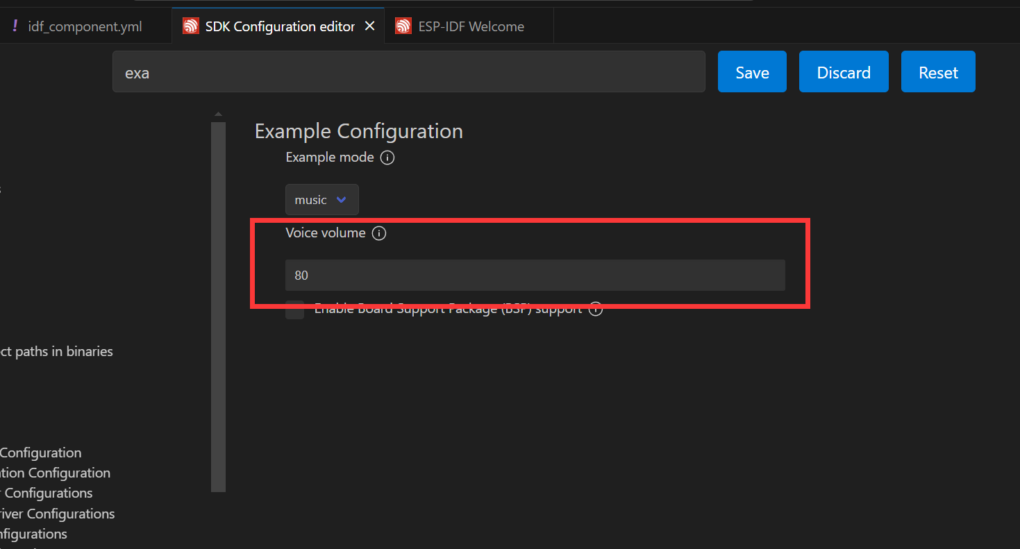
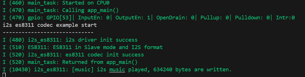
Connect a speaker, you can directly compile, flash, and monitor by clicking. After completion, the terminal will display the following result, indicating that the ESP32-P4-WIFI6-Touch-LCD-X is now playing audio.
When the
echomode is set in the settings, the audio will be recorded by the microphone and output through the speaker.
7. MIPI-DSI Display Example
The ESP32-P4 utilizes the ESP32-P4NRW32 chip, which features the following new capabilities:
- Compliant with the MIPI-DSI protocol, using D-PHY v1.1, supporting up to 2-lane x 1.5Gbps (3Gbps total)
- Supports RGB888, RGB565, and YUV422 input formats
- Supports RGB888, RGB666, and RGB565 output formats
- Uses video mode to output video streams and supports outputting fixed image patterns
For MIPI-DSI image processing, it can also utilize the 2D-DMA controller, supporting the PPA and JPEG codec peripherals.
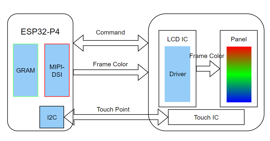
MIPI-DSI LCD Driving Principle
Hardware Required
ESP32-P4-WIFI6-Touch-LCD-X Any Kit
Display Initialization Steps
The compatible screen driver has been packaged as a component, available in the ESP Component Registry
Open the corresponding project, select the esp32p4 target, then proceed by clicking to compile, flash, and monitor. Upon completion, you can observe that the screen has lit up and is displaying color bars.

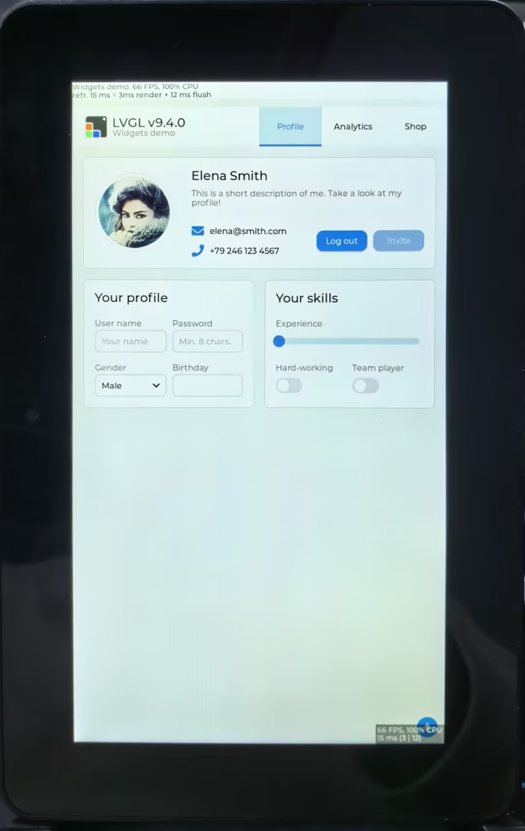
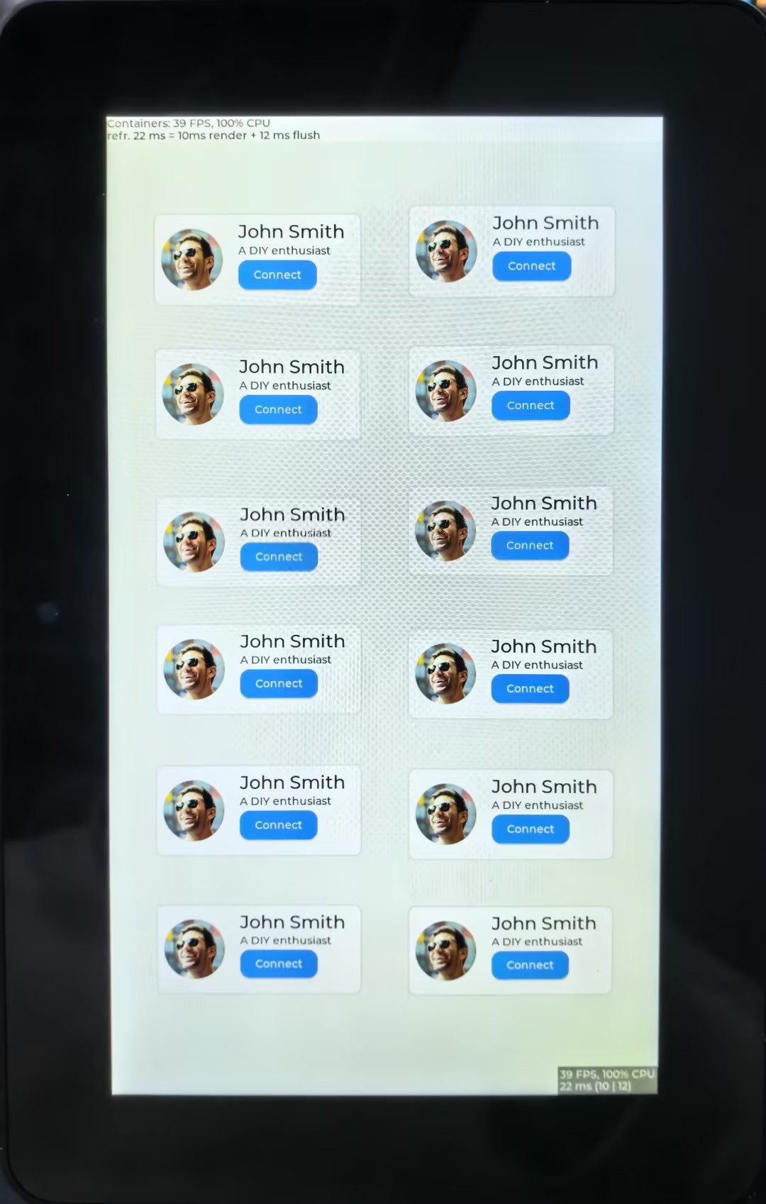
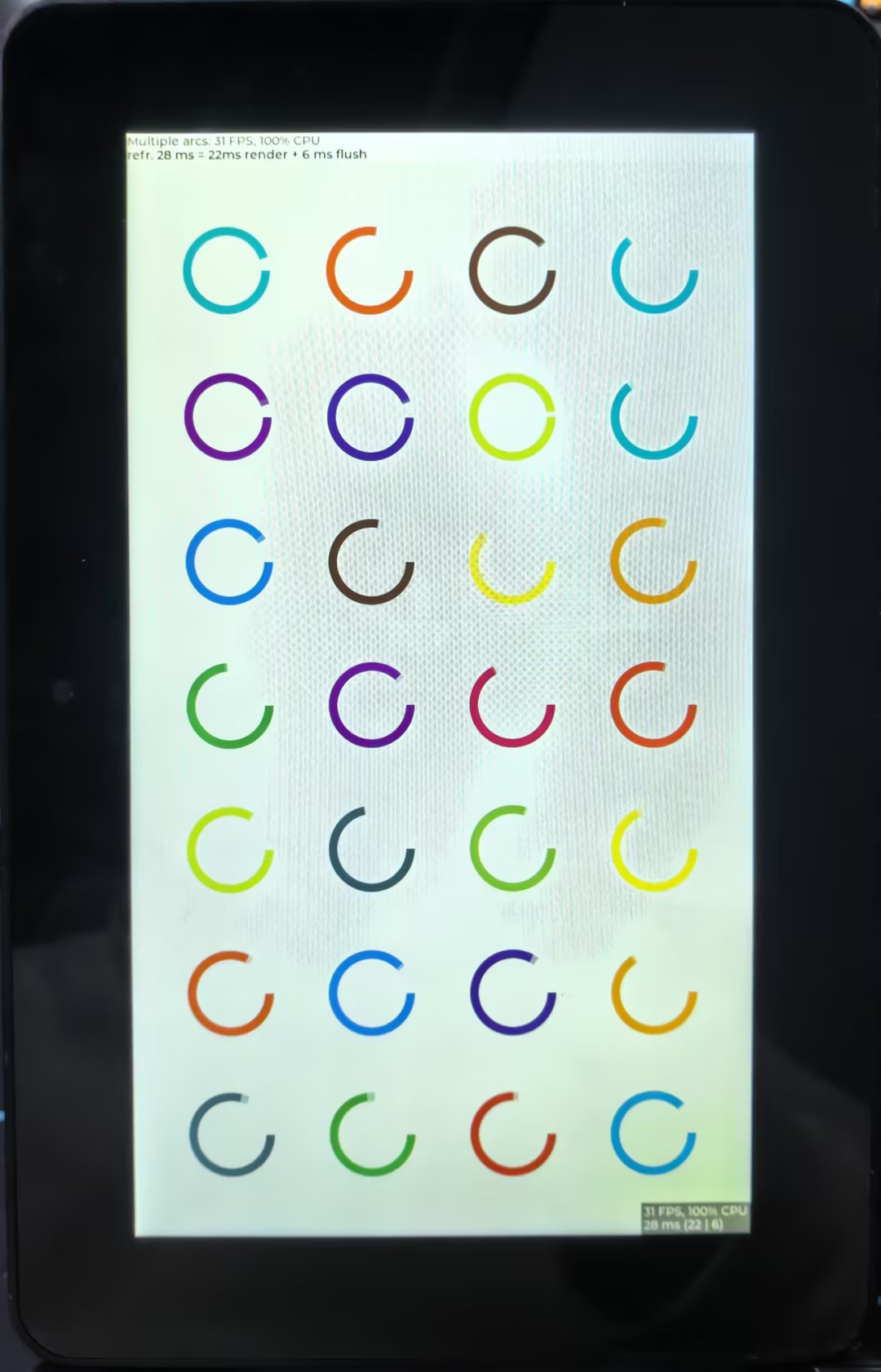
8. LVGL HMI Human-Machine Interface
This example shows that the ESP32-P4 displays LVGL images through the MIPI DSI interface, which fully demonstrates the powerful image processing capabilities of the ESP32-P4
Hardware Required
ESP32-P4-WIFI6-Touch-LCD-X Any Kit
Display Initialization Steps
- The compatible screen driver is packaged as a component and invoked via the BSP (Board Support Package).
- After opening the project, configure the relevant parameters in menuconfig under the Display settings. Select the esp32p4 target, then proceed by clicking to compile, flash, and monitor. Upon completion, the display will show the rendered images.
   |
|---|
9. Camera LCD Display
This example showcases ESP32-P4's robust image processing power by capturing video from a camera via the MIPI CSI interface and displaying it in real-time on a screen via the MIPI DSI interface.
Hardware Required
ESP32-P4-WIFI6-Touch-LCD-X Any Kit
Display Initialization Steps
- The compatible screen driver is packaged as a component and invoked via the BSP (Board Support Package).
- After opening the project, configure the relevant parameters in menuconfig under the Display settings. Select the esp32p4 target, then proceed by clicking to compile, flash, and monitor. Upon completion, the display will show the rendered images.
10. MP4 Player
This example showcases ESP32-P4's robust image processing power by capturing video from a camera via the MIPI CSI interface and displaying it in real-time on a screen via the MIPI DSI interface.
Hardware Required
- ESP32-P4-WIFI6-Touch-LCD-X Any Kit
- A TF card (with storage capacity ≥ 16GB, Class 10, formatted in FAT32)
- File Format:
.mp4 - Download Link: test_video.mp4
Recommended Settings
High Quality (720x1280/800x1280, RGB888 displays):
# scale=800:1280
ffmpeg -i input.mp4 -c:v mjpeg -q:v 3 -vf scale=720:1280 -r 20 -c:a aac output.mp4
Display Initialization Steps
- Place the provided video file onto the TF card, and then insert the card into the main board's card slot.
- After opening the project, configure the relevant parameters in menuconfig under the Display settings. Select the esp32p4 target, then proceed by clicking to compile, flash, and monitor. Upon completion, the display will show the rendered images.
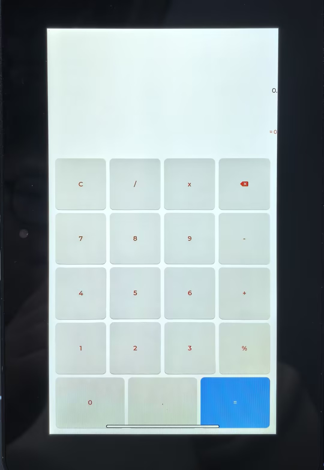
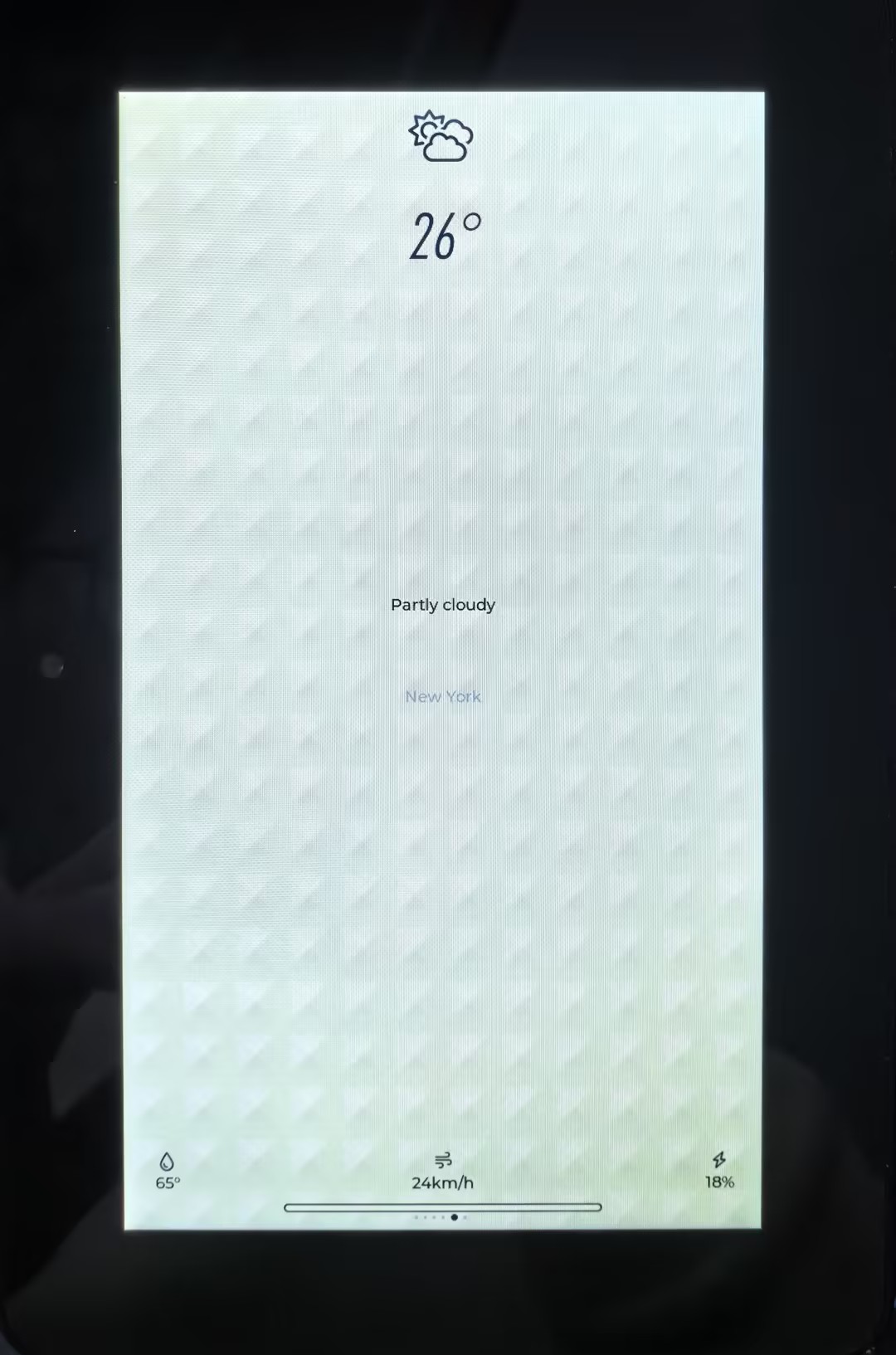
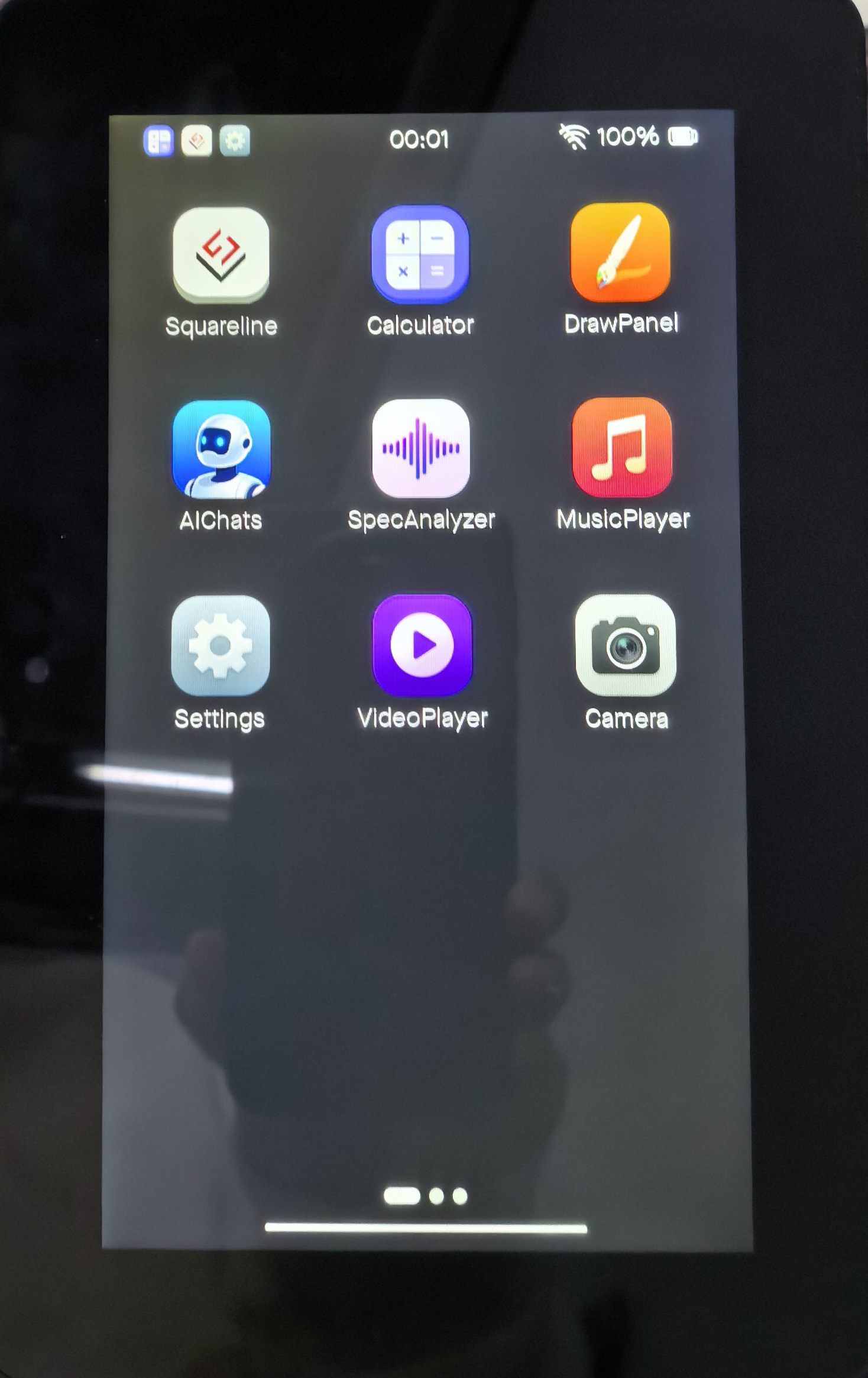
11. ESP-Phone
This example is based on ESP_Brookesia and demonstrates an Android-like interface containing various applications. This example uses the board's MIPI-DSI port, MIPI-CSI port, ESP32-C6, TF card slot, and audio jack. Based on this example, you can create a use case based on ESP_Brookesia to efficiently develop multimedia applications.
Hardware Required
- ESP32-P4-WIFI6-Touch-LCD-X Any Kit
Display Initialization Steps
- After opening the project, select esp32p4 core, and you can directly click to compile, flash, and monitor. Upon completion, the display will show the rendered images.
   |
|---|
Resources
1. Hardware Resources
- Development Board Design File
2. Technical Manuals
- Official ESP32-P4 Chip Manuals
- Datasheet: ESP32-P4-Datasheet
- Technical Manual: ESP32-P4 Technical Reference Manual
3. Demo
- Demo (GitHub): ESP32-P4-WIFI6-Touch-LCD-X
- Flashing tool: flash_download_tool.zip
Support
Monday-Friday (9:30-6:30) Saturday (9:30-5:30)
Email: services01@spotpear.com