- sales/support
Google Chat:---
- sales
+86-0755-88291180
- sales01
sales@spotpear.com
- sales02
dragon_manager@163.com
- support
tech-support@spotpear.com
- CEO-Complaints
zhoujie@spotpear.com
- Only Tech-Support
WhatsApp:13246739196
- Purchase/Shipping/Refund
WhatsApp:13424403025
- HOME
- >
- ARTICLES
- >
- Common Moudle
- >
- ESP
ESP32-S3-RGB-Matrix User Guide
Features
- Equipped with the ESP32-S3-N32R16 chip, featuring an Xtensa 32‑bit LX7 dual‑core processor running at up to 240 MHz
- Supports 2.4 GHz Wi‑Fi and Bluetooth 5 (BLE) dual‑mode communication
- Built‑in 512KB SRAM, 384KB ROM, stacked 32MB Flash and 16MB PSRAM, meeting storage needs in various scenarios
- Compatible with all sizes of the Matrix‑RGB series from the Waveshare store, capable of smoothly running LVGL and other graphical UI programs
- Onboard ES7210 echo cancellation chip for improved voice processing
- Onboard ES8311 low‑power audio codec chip supporting high‑quality audio input/output
- Dual‑microphone array supporting noise reduction and echo cancellation algorithms, suitable for voice recognition and wake‑word applications
- Onboard speaker connector supporting audio playback output, ready for direct speaker connection
- Integrated QMI8658 6‑axis IMU (3‑axis accelerometer + 3‑axis gyroscope) for motion detection
- Integrated SHTC3 temperature and humidity sensor for accurate environmental monitoring
- Onboard TF card slot for storing images, audio, and other file data, facilitating data read/write
- Onboard PCF85063 RTC real‑time clock chip, with a reserved SH1.0 battery connector for continuous timekeeping when power is off
- Reserved GPIO expansion header for peripheral expansion and function customization, adapting to diverse development needs
- Dual power supply interface design, supporting stable operation of up to six 64×64 Matrix‑RGB screens, with cascade expansion for large‑size displays
- Onboard USB Type‑C interface supporting power supply, program download, and debugging for convenient operation
- Onboard RST / BOOT buttons, where the BOOT button supports custom functions, enhancing development flexibility
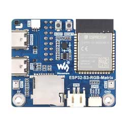
Onboard Resources
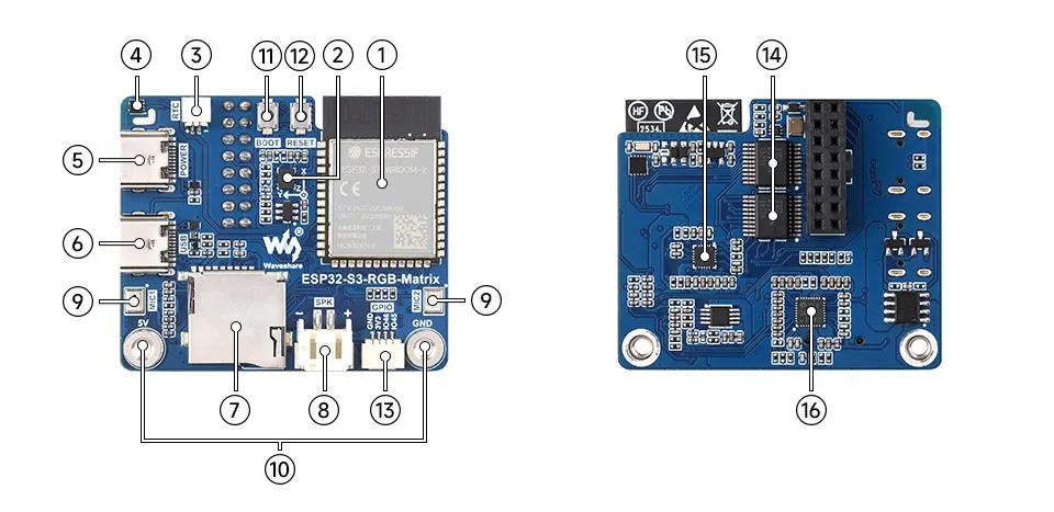
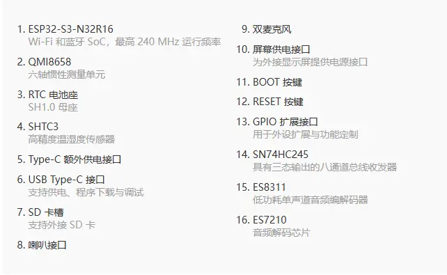
Interface Introduction
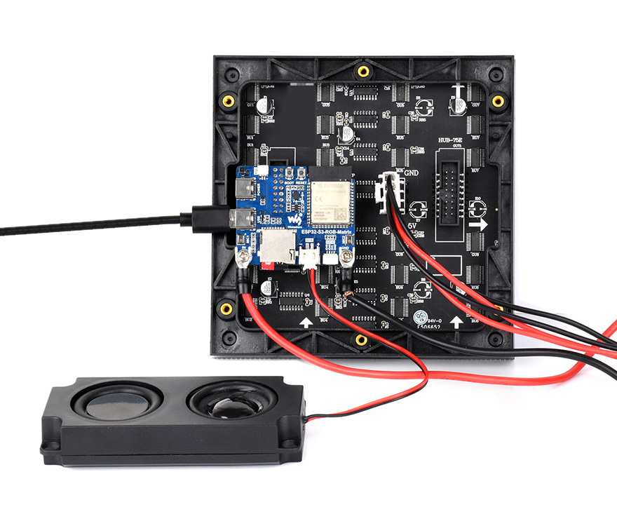
Dimensions
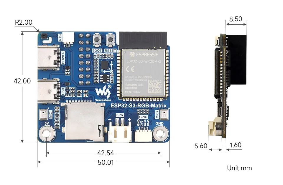
User Guide
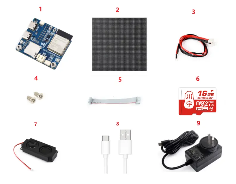
To help users quickly understand the features of the product, we provide a series of test examples that demonstrate how to use each interface. To run these examples, prepare the following components:
Component Preparation
- ESP32-S3-RGB-Matrix ×1
- Any model of LED screen x1 (you can prepare multiple if cascading is required)
- VH4 2PIN wire (approx. 500mm) ×1 (prepare multiple if cascading is required)
- Screw kit × 1
- 16PIN flat ribbon cable (approx. 200mm) ×1 (prepare multiple if cascading is required)
- TF card × 1
- 8Ω 5W speaker × 1
- USB cable Type-A male → Type‑C male ×1
- PSU-27W-USB-C-EU-B x 1 USB Type-C charger
Precautions
To cascade multiple screens, prepare several screens and several flat ribbon cables. Connect each screen to one end of a ribbon cable. If the power supply is insufficient, you can use a dual‑port USB Type‑C charger.
The TF card only supports MMC communication.
⚠️ USB Download Precautions (Important)
If the port is not recognized, please enter Boot mode:
- Press and hold the BOOT button
- Connect the USB cable to the computer
- Release the BOOT button
After the download is complete, press the RESET button to run the program.
The following options must be configured in menuconfig before compilation:
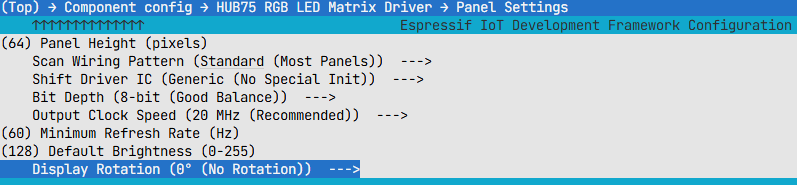
Panel Height = 64
Panel Width = 64
Configure according to the specific pixel size. Incorrect settings will cause display misalignment.
Scan Wiring Pattern = Standard
Scan wiring modes and select the most common standard mode.
Shift Driver IC = Generic
Initialize the driver chip in generic mode, suitable for most common panels.
Bit Depth = 8-bit
Medium color depth, providing a good balance between effect and performance.
Output Clock Speed = 20MHz
Data output speed; 20MHz is typically stable and sufficient.
Minimum Refresh Rate = 60Hz
Set the minimum refresh rate to 60Hz to reduce visible flicker.
Default Brightness = 128
Half of the maximum brightness, a compromise between brightness and power consumption.
Display Rotation = 0°
No rotation, display in the default orientation.
Working with Arduino
This chapter contains the following sections. Please read as needed:
Arduino Getting Started
New to Arduino ESP32 development and looking for a quick start? We have prepared a comprehensive Getting Started Tutorial for you.
- Section 0: Getting to Know ESP32
- Section 1: Installing and Configuring Arduino IDE
- Section 2: Arduino Basics
- Section 3: Digital Output/Input
- Section 4: Analog Input
- Section 5: Pulse Width Modulation (PWM)
- Section 6: Serial Communication (UART)
- Section 7: I2C Communication
- Section 8: SPI Communication
- Section 9: Wi-Fi Basics
- Section 10: Web Server
- Section 11: Bluetooth
- Section 12: LVGL GUI Development
- Section 13: Comprehensive Project
Note: This tutorial uses the ESP32-S3-Zero as a reference example, and all hardware code is based on its pinout. Before you start, we recommend checking the pinout of your development board to ensure the pin configuration is correct.
Setting Up Development Environment
1. Installing and Configuring Arduino IDE
Please refer to the tutorial Installing and Configuring Arduino IDE to download and install the Arduino IDE and add ESP32 support.
| Board Name | Board Installation Requirement | Version Requirement |
|---|---|---|
| esp32 by Espressif Systems | "Install Offline" / "Install Online" | 3.3.7 |
Arduino Settings:
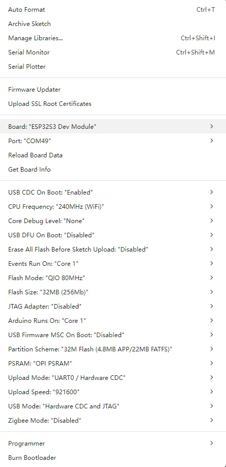
2. Running the Examples
Arduino example programs: ESP32-S3-RGB-Matrix Example - GitHub
Below are the purpose, key points, and operational effects for each example (for quick start).
| Example | Basic Description |
|---|---|
| 01_SimpleTestShapes | Simple shape drawing |
| 02_PatternPlasma | Plasma effect |
| 03_DoubleBuffer | Double buffer test, draw dynamic graphics |
| 04_OtherShiftDriverPanel | Drive the panel using a driver chip |
| 05_AnimatedGIFPanel_SD | Read and display GIF images from the TF card |
| 06_BitmapIcons | Display BMP images |
| 07_Pixel_Mapping_Test | Show basic HUB75 control logic |
Note:
- When driving a P4 series panel, be sure to add
mxconfig.driver = HUB75_I2S_CFG::SHIFTREG;in the code, otherwise display anomalies may occur.
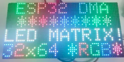
01_SimpleTestShapes
Code Analysis
loop(): Sequentially performs text drawing, solid color filling, and screen clearing operations to quickly verify the basic display functionality of the panel.drawText(wheelval): Draws text and changes color effects based onwheelvalto check whether character rendering and color changes are normal.dma_display->fillScreen(): Fills the screen with solid colors such as black, red, green, blue, and white in sequence to observe the full-screen refresh and color display effect.delay(2000): Pauses for 2 seconds after each display step for easy visual confirmation.dma_display->clearScreen(): Clears the screen after the test to avoid residual content from the previous frame.
void loop() {

  // animate by going through the colour wheel for the first two lines
  drawText(wheelval);
  wheelval +=1;
  delay(2000);
  dma_display->clearScreen();
  dma_display->fillScreen(myBLACK);
  delay(2000);
  dma_display->fillScreen( myRED);
  delay(2000);
  dma_display->fillScreen(myGREEN);
  delay(2000);
  dma_display->fillScreen(myBLUE);
  delay(2000);
  dma_display->fillScreen(myWHITE);
  delay(2000);
  dma_display->clearScreen();

}
Operation Result
02_PatternPlasma
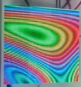
Code Analysis
loop(): Generates a dynamic plasma effect through per-pixel calculation and palette mapping.for (int x ...)/for (int y ...): Iterates over each pixel of the panel, calculating and drawing colors point by point.sin8(),sin16(),cos16(): Combine coordinates andtime_counterto generate a dynamically changing intermediate valuev, creating a flowing ripple effect.ColorFromPalette(currentPalette, (v >> 8)): Fetches a color from the current palette based on the calculation result.dma_display->drawPixelRGB888(): Writes the calculated RGB color to the current pixel.time_counter,cycles,fps: Used to drive animation changes, count the number of cycles, and calculate the drawing frame rate.if (cycles >= 1024): Resets the counter and randomly switches the palette to achieve automatic cycling through different color schemes.Serial.printf_P(): Outputs theEffect fpsevery 5 seconds to observe the effect drawing speed.
void loop() {

    for (int x = 0; x < PANE_WIDTH; x++) {
            for (int y = 0; y <  PANE_HEIGHT; y++) {
                int16_t v = 128;
                uint8_t wibble = sin8(time_counter);
                v += sin16(x * wibble * 3 + time_counter);
                v += cos16(y * (128 - wibble)  + time_counter);
                v += sin16(y * x * cos8(-time_counter) / 8);

                currentColor = ColorFromPalette(currentPalette, (v >> 8)); //, brightness, currentBlendType);
                dma_display->drawPixelRGB888(x, y, currentColor.r, currentColor.g, currentColor.b);
            }
    }

    ++time_counter;
    ++cycles;
    ++fps;

    if (cycles >= 1024) {
        time_counter = 0;
        cycles = 0;
        currentPalette = palettes[random(0,sizeof(palettes)/sizeof(palettes[0]))];
    }

    // print FPS rate every 5 seconds
    // Note: this is NOT a matrix refresh rate, it's the number of data frames being drawn to the DMA buffer per second
    if (fps_timer + 5000 < millis()){
      Serial.printf_P(PSTR("Effect fps: %d\n"), fps/5);
      fps_timer = millis();
      fps = 0;
    }
} // end loop
Operation Result
03_DoubleBuffer
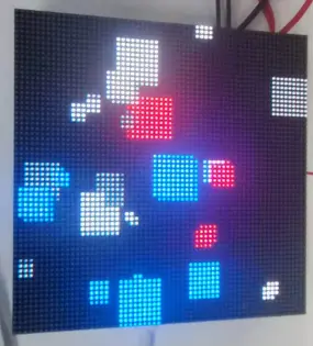
Code Analysis
loop(): Demonstrates the full flow of double-buffered animation, including buffer swapping, back‑buffer drawing, and motion state updates.display->flipDMABuffer(): Switches subsequent drawing to the back buffer that is not currently displayed, used to reduce flicker in dynamic graphics.delay(1000/display->calculated_refresh_rate): Waits long enough for the current frame to finish displaying, avoiding tearing or flicker caused by flipping the buffer too early.display->clearScreen(): Clears the back buffer to prepare for drawing the next frame.delay(25): Simulates a time-consuming drawing process, making it easier to visually observe the smoothness effect after enabling double buffering.display->fillRect(): Draws multiple moving squares to form a dynamic test screen.velocityx/velocityylogic: Reverses the movement direction when a square hits the screen edge, creating a bounce effect.Squares[i].xpos/Squares[i].yposupdate: Updates the square coordinates based on the velocity, driving the next frame of animation.
void loop()
{

  // Flip all future drawPixel calls to write to the back buffer which is NOT being displayed.
  display->flipDMABuffer();

  // SUPER IMPORTANT: Wait at least long enough to ensure that a "frame" has been displayed on the LED Matrix Panel before the next flip!
  delay(1000/display->calculated_refresh_rate);

  // Now clear the back-buffer we are drawing to.
  display->clearScreen();

  // This is here to demonstrate flicker if double buffering is disabled. Emulates a long draw routine that would typically occur after a 'clearscreen'.
  delay(25);


  for (int i = 0; i < numSquares; i++)
  {
    // Draw rect and then calculate
    display->fillRect(Squares[i].xpos, Squares[i].ypos, Squares[i].square_size, Squares[i].square_size, Squares[i].colour);

    if (Squares[i].square_size + Squares[i].xpos >= display->width()) {
      Squares[i].velocityx *= -1;
    } else if (Squares[i].xpos <= 0) {
      Squares[i].velocityx = abs (Squares[i].velocityx);
    }

    if (Squares[i].square_size + Squares[i].ypos >= display->height()) {
      Squares[i].velocityy *= -1;
    } else if (Squares[i].ypos <= 0) {
      Squares[i].velocityy = abs (Squares[i].velocityy);
    }

    Squares[i].xpos += Squares[i].velocityx;
    Squares[i].ypos += Squares[i].velocityy;
  }
}
Operation Result
04_OtherShiftDriverPanel
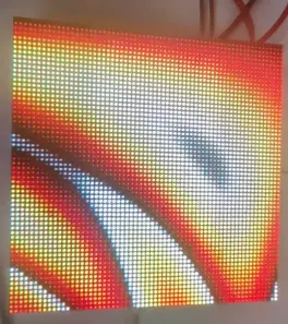
Code Analysis
loop(): Continuously generates a full‑screen dynamic effect to verify display compatibility with panels using shift‑register driver chips.for (int x ...)/for (int y ...): Iterates over each pixel of the screen, calculating the color value for each pixel individually.sin8(),sin16(),cos16(): Combine coordinates andtime_counterto generate a continuously changing color index.ColorFromPalette(currentPalette, (v >> 8) + 127): Maps the intermediate value to a final color from the palette.dma_display->drawPixelRGB888(): Writes the RGB color point‑by‑point to the DMA display buffer.time_counter,cycles,fps: Used to drive animation changes, control the color‑cycling period, and count the drawing frame rate.if (cycles >= 1024): Periodically resets animation parameters and randomly switches the palette for easy observation of display effects under different color schemes.Serial.printf_P(): Periodically outputs FPS information to evaluate the current pattern drawing speed.
void loop() {
   for (int x = 0; x <  dma_display->width(); x++) {
        for (int y = 0; y <  dma_display->height(); y++) {
            int16_t v = 0;
            uint8_t wibble = sin8(time_counter);
            v += sin16(x * wibble * 3 + time_counter);
            v += cos16(y * (128 - wibble)  + time_counter);
            v += sin16(y * x * cos8(-time_counter) / 8);

            currentColor = ColorFromPalette(currentPalette, (v >> 8) + 127); //, brightness, currentBlendType);
            dma_display->drawPixelRGB888(x, y, currentColor.r, currentColor.g, currentColor.b);
        }
    }

    ++time_counter;
    ++cycles;
    ++fps;

    if (cycles >= 1024) {
        time_counter = 0;
        cycles = 0;
        currentPalette = palettes[random(0,sizeof(palettes)/sizeof(palettes[0]))];
    }

    // print FPS rate every 5 seconds
    // Note: this is NOT a matrix refresh rate, it's the number of data frames being drawn to the DMA buffer per second
    if (fps_timer + 5000 < millis()){
      Serial.printf_P(PSTR("Effect fps: %d\n"), fps/5);
      fps_timer = millis();
      fps = 0;
    }
}
Operation Result
05_AnimatedGIFPanel_SD
Code Analysis
setup(): Completes initializations of the TF card, HUB75 panel, and GIF decoder, preparing for GIF animation playback.SD_MMC.setPins(): Configures the clock, command, and data pins used by the TF card.SD_MMC.begin("/sdcard", true): Mounts the TF card file system in 1‑bit mode.SD_MMC.cardType(),cardSize(),totalBytes(),usedBytes(): Reads the card type, capacity, and space usage information to confirm storage medium status.HUB75_I2S_CFG mxconfig(...): Configures the width, height, and cascade count of the HUB75 panel.dma_display = new MatrixPanel_I2S_DMA(mxconfig): Creates the DMA display object.dma_display->begin(): Starts DMA display and allocates the display buffer.SD_MMC.open("/gifs"): Opens the GIF file directory.root.openNextFile(): Iterates through files in the/gifsdirectory.GifFiles.push_back(filename): Saves the found GIF file paths to a list for later loop playback.gif.begin(LITTLE_ENDIAN_PIXELS): Initializes the GIF decoder and sets the pixel byte order.
void setup()
{
    Serial.begin(115200);

    // **************************** Setup TF Card access via SD_MMC 1-bit ****************************
    if (!SD_MMC.setPins(BSP_SD_CLK, BSP_SD_CMD, BSP_SD_D0)) {
        Serial.println("SD_MMC setPins Failed");
        return;
    }

    if (!SD_MMC.begin( "/sdcard", true)) {
        Serial.println("Card Mount Failed");
        return;
    }
    uint8_t cardType = SD_MMC.cardType();

    if (cardType == CARD_NONE) {
        Serial.println("No TF card attached");
        return;
    }

    Serial.print("TF Card Type: ");
    if (cardType == CARD_MMC) {
        Serial.println("MMC");
    } else if (cardType == CARD_SD) {
        Serial.println("SDSC");
    } else if (cardType == CARD_SDHC) {
        Serial.println("SDHC");
    }else{
        Serial.println("UNKNOWN");
    }

    uint64_t cardSize = SD_MMC.cardSize() / (1024 * 1024);
    Serial.printf("TF Card Size: %lluMB\n", cardSize);

    //listDir(SD_MMC, "/", 1, false);

    Serial.printf("Total space: %lluMB\n", SD_MMC.totalBytes() / (1024 * 1024));
    Serial.printf("Used space: %lluMB\n", SD_MMC.usedBytes() / (1024 * 1024));


    // **************************** Setup DMA Matrix ****************************
    HUB75_I2S_CFG mxconfig(
      PANEL_RES_X,   // module width
      PANEL_RES_Y,   // module height
      PANEL_CHAIN    // Chain length
    );

    // Keep ESP32-S3 default HUB75 mapping to avoid Flash/PSRAM reserved pins.

    //mxconfig.clkphase = false;
    //mxconfig.driver = HUB75_I2S_CFG::FM6126A;

    // Display Setup
    dma_display = new MatrixPanel_I2S_DMA(mxconfig);

    // Allocate memory and start DMA display
    if( not dma_display->begin() )
        Serial.println("****** !KABOOM! HUB75 memory allocation failed ***********");

    dma_display->setBrightness8(128); //0-255
    dma_display->clearScreen();


    // **************************** Setup Sketch ****************************
    Serial.println("Starting AnimatedGIFs Sketch");

    // TF CARD STOPS WORKING WITH DMA DISPLAY ENABLED>...

    File root = SD_MMC.open("/gifs");
    if (!root) {
        Serial.println("Failed to open directory");
        return;
    }

    File file = root.openNextFile();
    while (file) {
        if(!file.isDirectory())
        {
            Serial.print("  FILE: ");
            Serial.print(file.name());
            Serial.print("  SIZE: ");
            Serial.println(file.size());

            std::string filename = "/gifs/" + std::string(file.name());
            Serial.println(filename.c_str());

            GifFiles.push_back( filename );
         //   Serial.println("Adding to gif list:" + String(filename));
            totalFiles++;

        }
        file = root.openNextFile();
    }

    file.close();
    Serial.printf("Found %d GIFs to play.", totalFiles);
    //totalFiles = getGifInventory("/gifs");


  // This is important - Set the right endianness.
  gif.begin(LITTLE_ENDIAN_PIXELS);

}
Operation Result
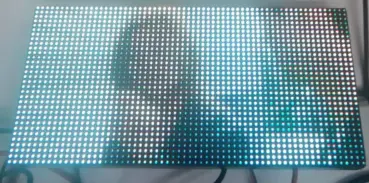
06_BitmapIcons
Code Analysis
setup(): Completes display initialization and draws a Wi-Fi icon with a fade‑in effect to verify that bitmap resources and drawing interfaces are working properly.dma_display->begin(): Starts the HUB75 panel display.dma_display->setBrightness8(90): Sets the panel brightness.dma_display->fillScreen()/dma_display->clearScreen(): Clears the screen during initialization and between icon switches to avoid image retention.for (int r = 0; r < 255; r++): Gradually increases the red component to create a fade‑in animation.drawXbm565(0,0,64,32, wifi_image1bit, ...): Draws the Wi-Fi XBM bitmap onto the screen.loop(): Cycles through different icons, displaying them one after another.drawXbm565(5,0, 32, 32, icon_bits[current_icon]): Draws the icon data corresponding to the current index.icon_name[current_icon]: Outputs the name of the currently displayed icon via the serial port for debugging purposes.current_icon = (current_icon + 1) % num_icons: Updates the icon index cyclically to ensure the rotation does not go out of bounds.
void setup() {

  // put your setup code here, to run once:
  delay(1000); Serial.begin(115200); delay(200);


  /************** DISPLAY **************/
  Sprintln("...Starting Display");
  dma_display = new MatrixPanel_I2S_DMA(mxconfig);
  dma_display->begin();
  dma_display->setBrightness8(90); //0-255
  dma_display->clearScreen();

  dma_display->fillScreen(dma_display->color444(0, 0, 0));

  // Fade a Red Wi-Fi Logo In
  for (int r=0; r < 255; r++ )
  {
    drawXbm565(0,0,64,32, wifi_image1bit, dma_display->color565(r,0,0));
    delay(10);
  }

  delay(2000);
  dma_display->clearScreen();
}


void loop() {

  // Loop through Weather Icons
  Serial.print("Showing icon ");
  Serial.println(icon_name[current_icon]);
  drawXbm565(5,0, 32, 32, icon_bits[current_icon]);

  current_icon = (current_icon  +1 ) % num_icons;
  delay(2000);
  dma_display->clearScreen();

}
Operation Result
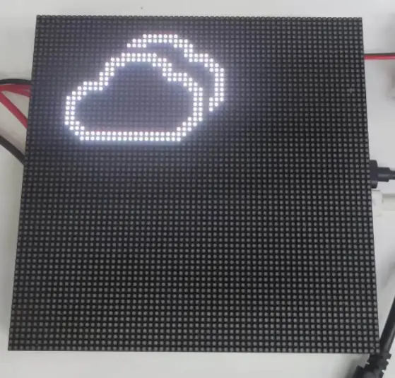
07_Pixel_Mapping_Test
Code Analysis
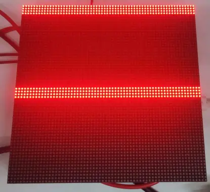
loop(): Lights pixels one by one in row‑column order to verify that the panel pixel mapping matches the software configuration.for (int i ...)/for (int j ...): Iterates over all pixel coordinates ofFourScanPanel.FourScanPanel->drawPixel(j, i, FourScanPanel->color565(255, 0, 0)): Lights the current pixel in red, creating an observable scanning trace.delay(30): Moves the scanning point slowly for easy observation of the actual lighting order.dma_display->clearScreen(): Clears the screen after a full‑panel scan to start the next test round.delay(2000): Pauses for 2 seconds after each scanning round to allow confirmation of mapping correctness.
void loop() {
  for (int i = 0; i < FourScanPanel->height(); i++)
  {
    for (int j = 0; j < FourScanPanel->width(); j++)
    {
      FourScanPanel->drawPixel(j, i, FourScanPanel->color565(255, 0, 0));
      delay(30);
    }
  }
  delay(2000);
  dma_display->clearScreen();
} // end loop
Operation Result
ESP-IDF
This chapter contains the following sections. Please read as needed:
ESP-IDF Getting Started
New to ESP32 ESP-IDF development and looking to get started quickly? We have prepared a general Getting Started Tutorial for you.
- Section 1: Environment Setup
- Section 2: Running Examples
- Section 3: Creating a Project
- Section 4: Using Components
- Section 5: Debugging
- Section 6: FreeRTOS
- Section 7: Peripherals
- Section 8: Wi-Fi Programming
- Section 9: BLE Programming
Please Note: This tutorial uses the ESP32-S3-Zero as a teaching example, and all hardware code is based on its pinout. Before you start, it is recommended that you check the pinout of your development board to ensure the pin configuration is correct.
Setting Up Development Environment
The following guide uses Windows as an example, demonstrating development using VS Code + the ESP-IDF extension. macOS and Linux users should refer to the official documentation.
The screenshots in this section use ESP-IDF V5.5.2 as an example. When installing, please select the ESP-IDF version that matches your board's example.
Install the ESP-IDF Development Environment
Download the installation manager from the ESP-IDF Installation Manager page. This is Espressif's latest cross-platform installer. The following steps demonstrate how to use its offline installation feature.
Click the Offline Installer tab on the page, then select Windows as the operating system and the ESP-IDF version you need (the version shown in the screenshot is for reference only — choose the version that fits your actual needs).
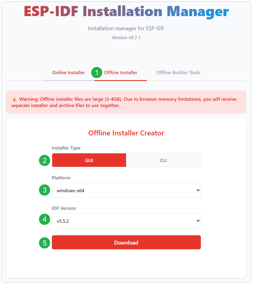
After confirming your selection, click the download button. The browser will automatically download two files: the ESP-IDF Offline Package (.zst) and the ESP-IDF Installer (.exe).
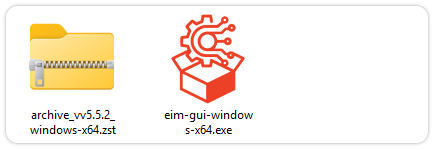
Please wait for both files to finish downloading.
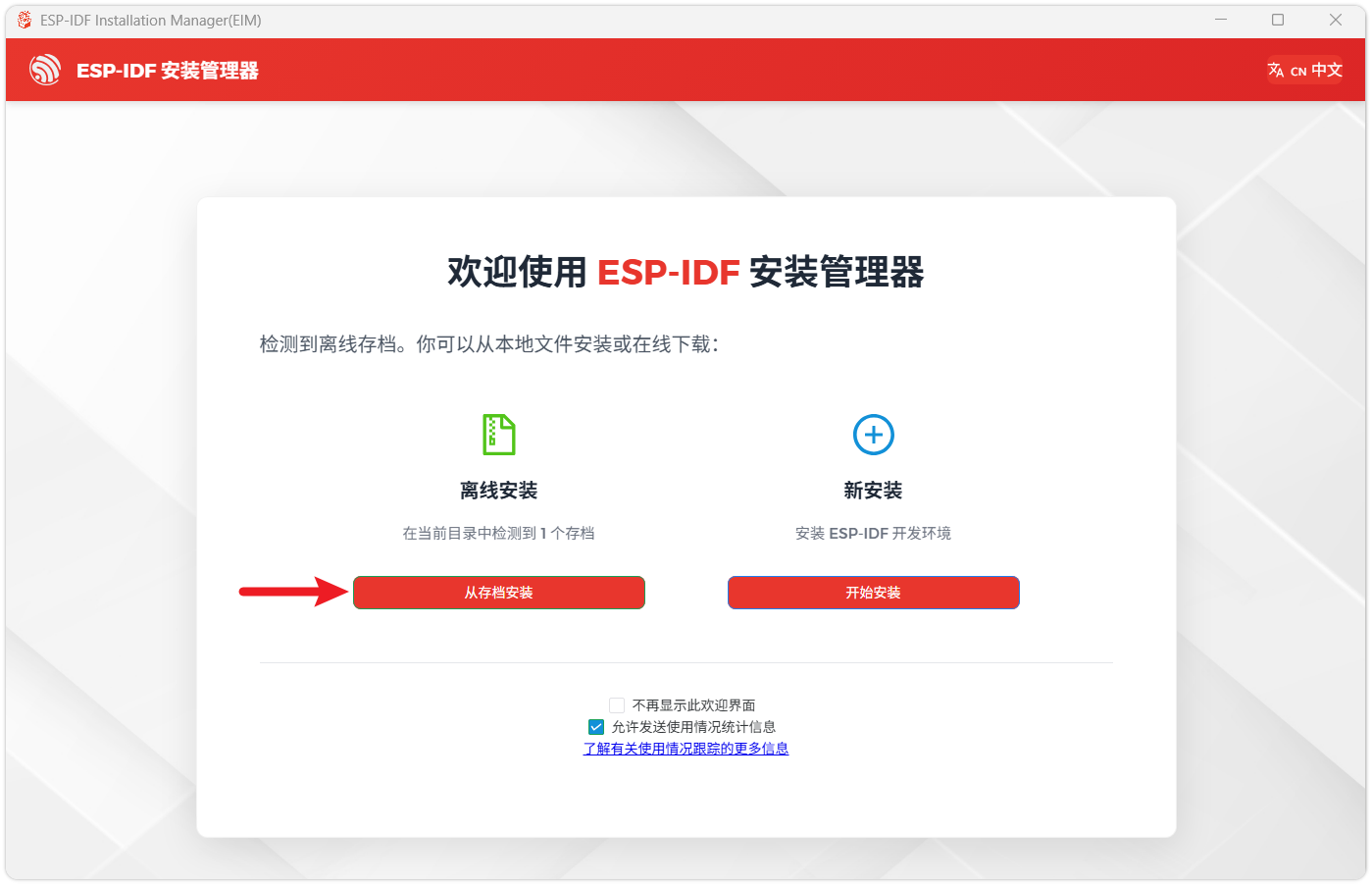
Once the download is complete, double-click to run the ESP-IDF Installer (eim-gui-windows-x64.exe).
The installer will automatically detect if the offline package exists in the same directory. Click Install from archive.
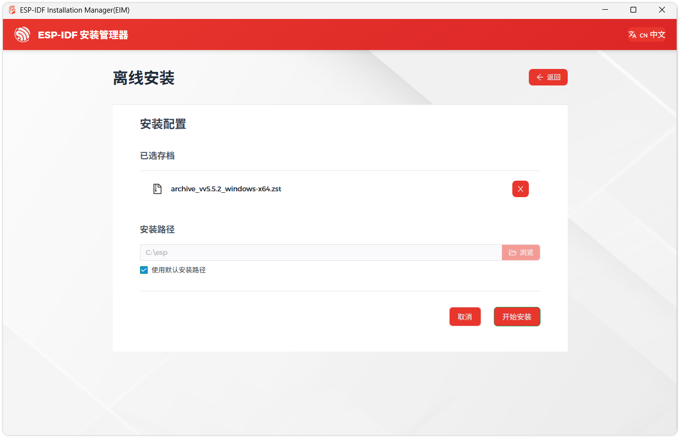
Next, select the installation path. We recommend using the default path. If you need to customize it, ensure the path does not contain Chinese characters or spaces. Click Start installation to proceed.
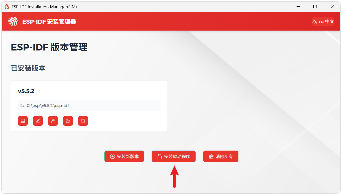
When you see the following screen, the ESP-IDF installation is successful.
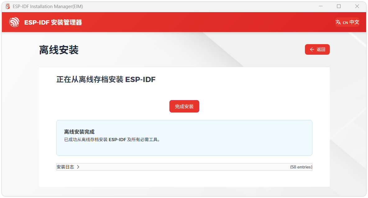
We recommend installing the drivers as well. Click Finish installation, then select Install driver.
Install Visual Studio Code and the ESP-IDF Extension
Download and install Visual Studio Code.
During installation, it is recommended to check Add "Open with Code" action to Windows Explorer file context menu to facilitate opening project folders quickly.
In VS Code, click the Extensions icon
 in the Activity Bar on the side (or use the shortcut Ctrl + Shift + X) to open the Extensions view.
Enter ESP-IDF in the search box, locate the ESP-IDF extension, and click Install.
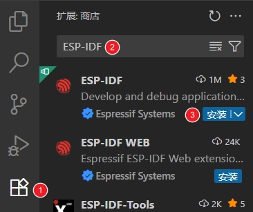
For ESP-IDF extension versions ≥ 2.0, the extension will automatically detect and recognize the ESP-IDF environment installed in the previous steps, requiring no manual configuration.
Example
IDF example: ESP32-S3-RGB-Matrix Example - GitHub
Below are the purpose, key points, and operational effects for each example (for quick start).
| Example | Basic Description |
|---|---|
| 01_Matrix_RGBW | Simple test of RGBW LED color switching |
| 02_Matrix_Font_5x7 | Test 5x7 font display |
| 03_Matrix_QMI | Test QMI functionality display |
| 04_Matrix_RTC | Test RTC time display |
| 05_Matrix_SDCard | Test TF card mounting and capacity reading |
| 06_Matrix_SHTC3 | Test SHTC3 temperature and humidity sensor |
| 07_Matrix_WiFi | Test Wi-Fi connection |
| 08_Matrix_Audio | Test audio playback |
- The three examples 03_Matrix_QMI, 06_Matrix_SHTC3, and 08_Matrix_Audio are designed for a 64x64 pixel screen. If used with other screen sizes, text display may overlap or become misaligned.
01_Matrix_RGBW
Code Analysis
rgbw_start(): Cycles through the onboard RGBW LED colors to verify that the LED driver and logging output are functioning properly.sizeof(rgbw_colors) / sizeof(rgbw_colors[0]): Calculates the length of the preset color array for cycling.bsp_display_lock(): Locks the display before operating to avoid conflicts with other display tasks.lv_obj_set_style_bg_color(screen, lv_color_hex(0x000000), 0): Sets the current screen background to black, reducing on‑screen interference during the LED test.rgbw_set_color(rgbw_colors[color_index].hex_color): Outputs the current color value to the RGBW LED.ESP_LOGI(TAG, "Current color: %s", ...): Prints the current color name for debugging and observing the switching sequence.vTaskDelay(pdMS_TO_TICKS(2000)): Keeps each color for 2 seconds for easy observation.if (color_index >= num_colors): Returns to the start after reaching the end of the color array, enabling cyclic switching.
void rgbw_start(void) {
  /* =======================
   * 1. Basic Parameters
   * ======================= */
  int color_index = 0;
  const int num_colors = sizeof(rgbw_colors) / sizeof(rgbw_colors[0]);

  /* =======================
   * 2. Init Screen
   * ======================= */
  bool locked = bsp_display_lock(1000);
  if (locked) {
    lv_obj_t *screen = lv_scr_act();
    lv_obj_set_style_bg_color(screen, lv_color_hex(0x000000), 0);
    bsp_display_unlock();
  }
  /* =======================
   * 3. Loop Colors
   * ======================= */
  while (true) {
    locked = bsp_display_lock(1000);
    if (locked) {
      rgbw_set_color(rgbw_colors[color_index].hex_color);
      bsp_display_unlock();
    }
    ESP_LOGI(TAG, "Current color: %s", rgbw_colors[color_index].name);
    vTaskDelay(pdMS_TO_TICKS(2000));
    color_index++;
    if (color_index >= num_colors) {
      color_index = 0;
    }
  }
}
Operation Result
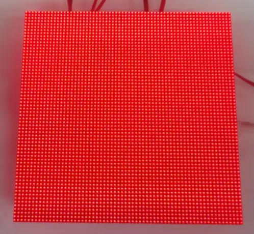 | 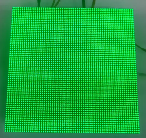 |
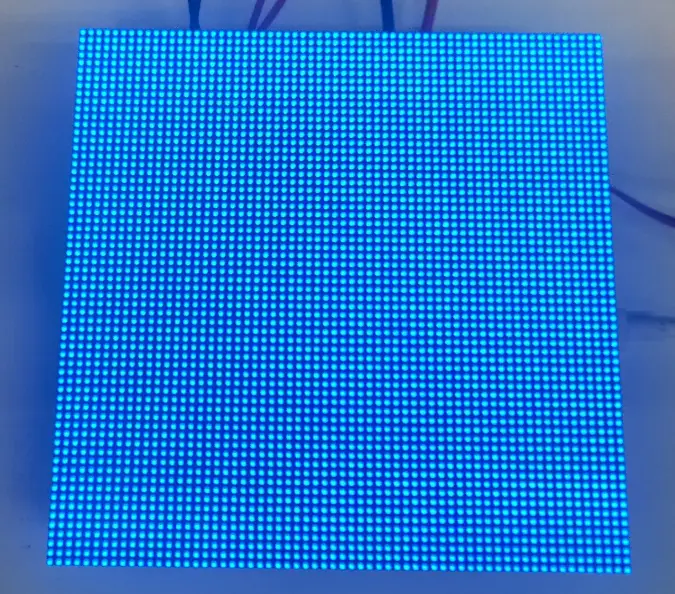 | 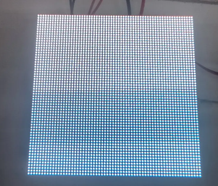 |
02_Matrix_Font_5x7
Code Analysis
font_5x7_start(): Starts the 5x7 font example interface and keeps the task running continuously.ESP_LOGI(TAG, "Matrix Font 5x7 start"): Outputs a start log to confirm that the example has entered the running state.bsp_display_lock(0): Locks before entering the LVGL display context to ensure safe interface initialization.font_5x7_ui_init(): Creates the UI objects needed for the 5x7 font example.font_5x7_ui_apply(): Applies the font, layout, default text, etc., to the interface.while (true): Keeps the task alive to prevent the example from exiting immediately after initialization.vTaskDelay(pdMS_TO_TICKS(1000)): Idle wait to reduce busy looping.
void font_5x7_start(void) {
  /* =======================
   * 1. Start Display
   * ======================= */
  ESP_LOGI(TAG, "Matrix Font 5x7 start");
  /* =======================
   * 2. Init UI (LVGL Locked)
   * ======================= */
  bool locked = bsp_display_lock(0);
  if (locked) {
    font_5x7_ui_init();
    font_5x7_ui_apply();
    bsp_display_unlock();
  }

  /* =======================
   * 3. Idle Loop
   * ======================= */
  while (true) {
    vTaskDelay(pdMS_TO_TICKS(1000));
  }
}
Operation Result
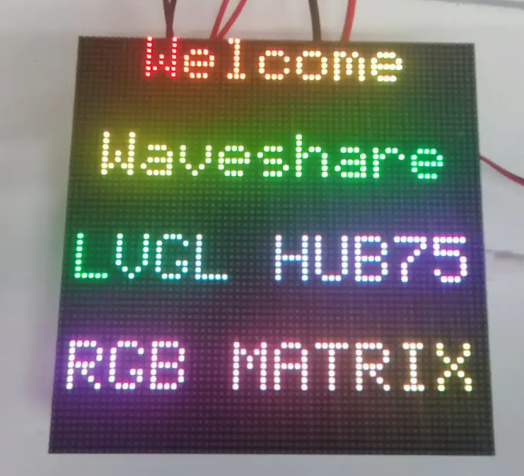
03_Matrix_QMI
Code Analysis
qmi_start(): Initializes the QMI8658 sensor UI, starts the driver, and configures periodic refreshing.qmi_ui_init(): Creates the UI for QMI8658 data display.middle_init_qmi8658(): Initializes the QMI8658 sensor driver.qmi_state.qmi_init_ret: Stores the sensor initialization result for the UI layer to determine status and show prompts.example_ui_install_timer(100, qmi_data_update): Installs a 100 ms periodic timer to refresh orientation or acceleration data.qmi_data_update: Updates sensor data and UI display in the timer callback.while (true): Keeps the task alive.vTaskDelay(pdMS_TO_TICKS(1000)): Idle wait to reduce resource usage.
void qmi_start(void) {
  /* =======================
   * 1. Start Display & UI
   * ======================= */
  bool locked = bsp_display_lock(0);
  if (locked) {
    qmi_ui_init();
    bsp_display_unlock();
  }

  /* =======================
   * 2. Start Sensor & Timer
   * ======================= */
  qmi_state.qmi_init_ret = middle_init_qmi8658();
  locked = bsp_display_lock(0);
  if (locked) {
    example_ui_install_timer(100, qmi_data_update);
    bsp_display_unlock();
  }

  /* =======================
   * 3. Idle Loop
   * ======================= */
  while (true) {
    vTaskDelay(pdMS_TO_TICKS(1000));
  }
}
Operation Result
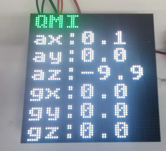
04_Matrix_RTC
Code Analysis
rtc_start(): Initializes the RTC UI, sets the time, configures the alarm, and enables real‑time refresh.rtc_ui_init(): Creates UI elements for time display.middle_rtc_init(): Initializes the RTC driver and underlying hardware interface.middle_rtc_set_time(rtc_state.rtc_time): Writes the initial time (from the state structure) to the RTC chip.middle_rtc_alarm(3): Configures an RTC alarm test condition to verify alarm functionality.example_ui_install_timer(1, rtc_data_update): Installs a high‑frequency refresh timer to keep the UI synchronized with the current time.rtc_data_update: Reads RTC data in the callback and updates the display content.while (true): Keeps the RTC example task running.
void rtc_start(void) {
  bool locked = bsp_display_lock(0);
  if (locked) {
    rtc_ui_init();
    bsp_display_unlock();
  }
  middle_rtc_init();
  middle_rtc_set_time(rtc_state.rtc_time);
  middle_rtc_alarm(3);
  locked = bsp_display_lock(0);
  if (locked) {
    example_ui_install_timer(1, rtc_data_update);
    bsp_display_unlock();
  }
  while (true) {
    vTaskDelay(pdMS_TO_TICKS(1000));
  }
}
Operation Result
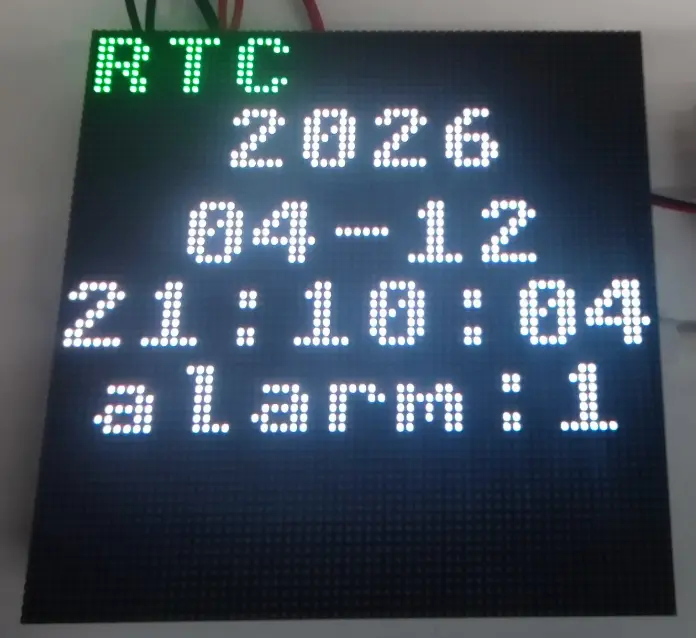
05_Matrix_SDCard
Code Analysis
sdcard_start(): Initializes the TFcard UI, starts the underlying driver, and configures periodic status refresh.sdcard_ui_init(): Creates UI components for displaying mount status, capacity, and storage information.middle_sdcard_init(): Performs low‑level TF card initialization, typically including bus configuration, card identification, and file system mounting.example_ui_install_timer(1000, sdcard_data_update): Installs a 1‑second periodic timer to refresh TF card status and capacity information.sdcard_data_update: Updates the TF card display content in the callback.while (true): Keeps the example task running.vTaskDelay(pdMS_TO_TICKS(1000)): Idle wait to reduce task usage.
void sdcard_start(void) {
  /* =======================
   * 1. Start Display & UI
   * ======================= */
  bool locked = bsp_display_lock(0);
  if (locked) {
    sdcard_ui_init();
    bsp_display_unlock();
  }

  /* =======================
   * 2. Init TF Card
   * ======================= */
  middle_sdcard_init();

  /* =======================
   * 3. Periodic Refresh
   * ======================= */
  locked = bsp_display_lock(0);
  if (locked) {
    example_ui_install_timer(1000, sdcard_data_update);
    bsp_display_unlock();
  }

  /* =======================
   * 4. Idle Loop
   * ======================= */
  while (true) {
    vTaskDelay(pdMS_TO_TICKS(1000));
  }
}
Operation Result
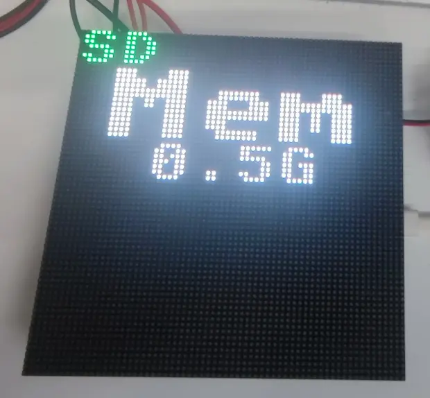
06_Matrix_SHTC3
Code Analysis
shtc3_start(): Initializes the SHTC3 UI, starts the driver, and refreshes temperature/humidity data periodically.shtc3_ui_init(): Creates UI elements for temperature, humidity, and status prompts.middle_init_shtc3(): Initializes the SHTC3 sensor driver.shtc3_state.shtc3_init_ret: Stores the initialization result for the UI layer to decide whether to show data normally.example_ui_install_timer(500, shtc3_data_update): Installs a 500 ms periodic timer to refresh sensor data.shtc3_data_update: Reads temperature and humidity information in the callback and refreshes the UI.while (true): Keeps the example task running.vTaskDelay(pdMS_TO_TICKS(1000)): Idle wait to reduce task usage.
void shtc3_start(void) {
  /* =======================
   * 1. Start Display & UI
   * ======================= */
  bool locked = bsp_display_lock(0);
  if (locked) {
    shtc3_ui_init();
    bsp_display_unlock();
  }
  /* =======================
   * 2. Init Sensor & Timer
   * ======================= */
  shtc3_state.shtc3_init_ret = middle_init_shtc3();
  locked = bsp_display_lock(0);
  if (locked) {
    example_ui_install_timer(500, shtc3_data_update);
    bsp_display_unlock();
  }

  /* =======================
   * 3. Idle Loop
   * ======================= */
  while (true) {
    vTaskDelay(pdMS_TO_TICKS(1000));
  }
}
Operation Result
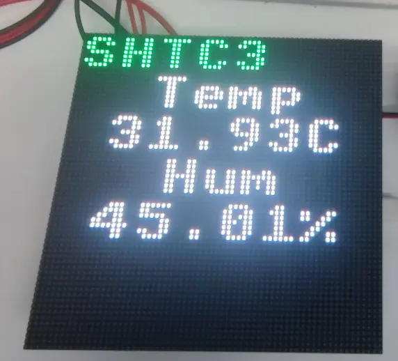
07_Matrix_WiFi
Code Analysis
wifi_start(): Initializes the Wi-Fi UI, configures STA parameters, starts the driver, and enables status refresh.wifi_ui_init(): Creates the network status display UI.middle_wifi_set_sta_config(WIFI_STA_SSID, WIFI_STA_PASS): Sets the SSID and password of the target access point.middle_wifi_init(): Starts the Wi-Fi driver and initiates the connection process.wifi_state.wifi_init_ret: Stores the Wi-Fi initialization result for the UI to display connection status.example_ui_install_timer(1000, wifi_data_update): Installs a 1‑second periodic timer to refresh connection status and network information.wifi_data_update: Updates the Wi-Fi connection status, IP address, and other UI content in the callback.while (true): Keeps the example task running.
void wifi_start(void) {
  /* =======================
   * 1. Start Display & UI
   * ======================= */
  bool locked = bsp_display_lock(0);
  if (locked) {
    wifi_ui_init();
    bsp_display_unlock();
  }

  /* =======================
   * 2. Configure & Enable Wi-Fi
   * ======================= */
  middle_wifi_set_sta_config(WIFI_STA_SSID, WIFI_STA_PASS);
  wifi_state.wifi_init_ret = middle_wifi_init();

  /* =======================
   * 3. Periodic Refresh
   * ======================= */
  locked = bsp_display_lock(0);
  if (locked) {
    example_ui_install_timer(1000, wifi_data_update);
    bsp_display_unlock();
  }

  /* =======================
   * 4. Idle Loop
   * ======================= */
  while (true) {
    vTaskDelay(pdMS_TO_TICKS(1000));
  }
}
Operation Result
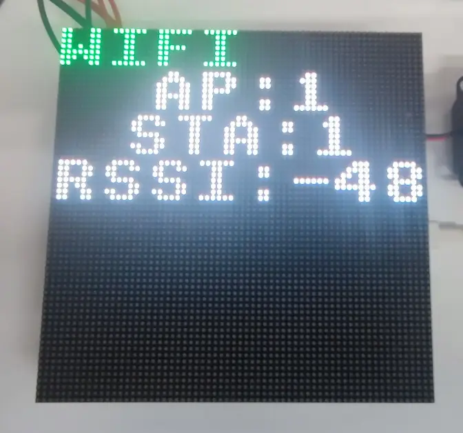
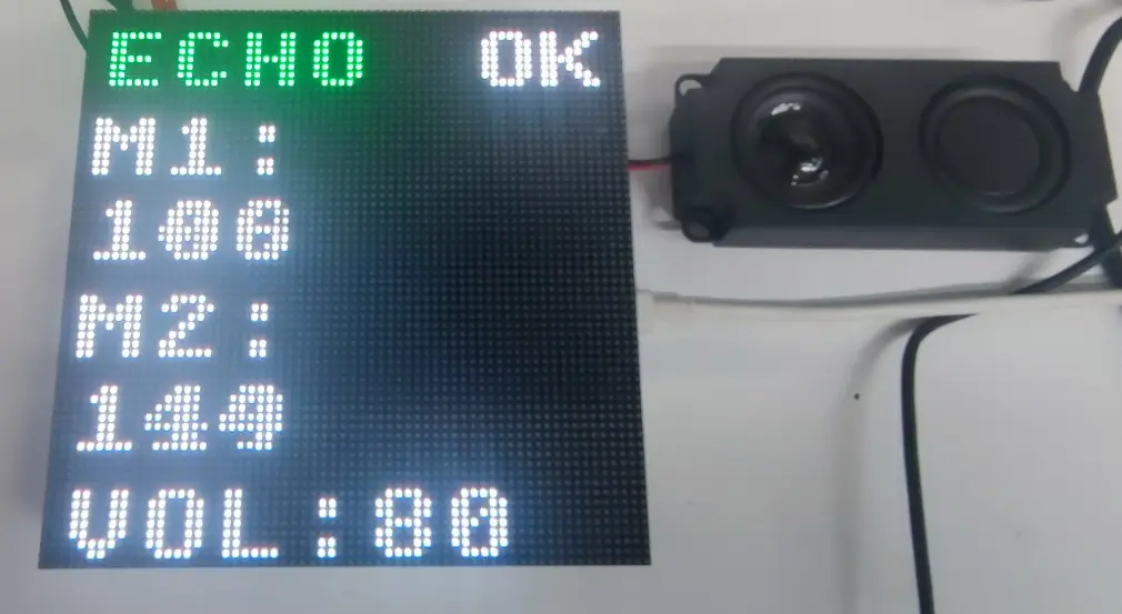
08_Matrix_Audio
Code Analysis
audio_start(): Initializes the audio UI, creates an audio task, and configures periodic status refresh.audio_ui_init(): Creates UI elements related to volume, playback status, or spectrum.audio_state.audio_out_vol = VOLUME: Sets the default audio output volume.xTaskCreate(audio_task, "aud", 4096, NULL, tskIDLE_PRIORITY + 4, NULL): Creates an independent audio task to handle audio logic in the background.example_ui_install_timer(100, audio_data_update): Installs a 100 ms periodic timer to sync the audio state with the UI.audio_data_update: Updates playback status, volume, or other audio information in the callback.while (true): Keeps the example task running.vTaskDelay(pdMS_TO_TICKS(1000)): Idle wait to reduce main task usage.
void audio_start(void) {
    /* =======================
     * 1. Start Display & UI
     * ======================= */
    bool locked = bsp_display_lock(0);
    if (locked) {
        audio_ui_init();
        bsp_display_unlock();
    }
    /* =======================
     * 2. Start Audio Task
     * ======================= */
    audio_state.audio_out_vol = VOLUME;
    xTaskCreate(audio_task, "aud", 4096, NULL, tskIDLE_PRIORITY + 4, NULL);
    /* =======================
     * 3. Periodic UI Refresh
     * ======================= */
    locked = bsp_display_lock(0);
    if (locked) {
        example_ui_install_timer(100, audio_data_update);
        bsp_display_unlock();
    }
    /* =======================
     * 4. Idle Loop
     * ======================= */
    while (true) {
        vTaskDelay(pdMS_TO_TICKS(1000));
    }
}
Operation Result
Resources
1. Hardware Resources
Development Board Design Files
2. Technical Manuals
- ESP32-S3 Chip Official Manuals
3. Example
4. Software Tools
- Arduino IDE Official Download Link
- VScode Official Download Link
- Serial Port Debug Assistant
- Flash_download_tool
- ESP32-Arduino Official Documentation
- ESP-IDF Official Resources
Support
Monday-Friday (9:30-6:30) Saturday (9:30-5:30)
Email: services01@spotpear.com