- sales/support
Google Chat:---
- sales
+86-0755-88291180
- sales01
sales@spotpear.com
- sales02
dragon_manager@163.com
- support
tech-support@spotpear.com
- CEO-Complaints
zhoujie@spotpear.com
- Only Tech-Support
WhatsApp:13246739196
- Purchase/Shipping/Refund
WhatsApp:13424403025
CM5-NANO-B User Guide
Overview
Introduction
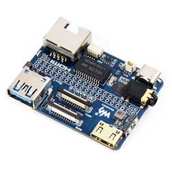
As the mini IO board of the Raspberry Pi Compute Module 5, CM5-NANO-A is a baseboard that can be used with the Raspberry Pi Compute Module 5. With powerful features integrated into a compact design, it is only the size of a CM5 and has interfaces including USB 3.2 Gen1, HDMI, audio, Ethernet port, etc.
Features and Precautions
1. It is forbidden to unplug and unplug any device other than USB when it is charged
2. Type C can be used as a USB SLAVE interface to flash images.
3. Onboard default USB 3.2 Gen1 port.
4. The onboard BOOT button, you can press the BOOT button before powering on, and connect to the computer through Type C to let the device enter the flashing mode
5. Do not connect other devices when using Type C to flash. Insufficient power supply for burning will cause the device to be unrecognized
6. USB TYPE A interface maximum power output 2A
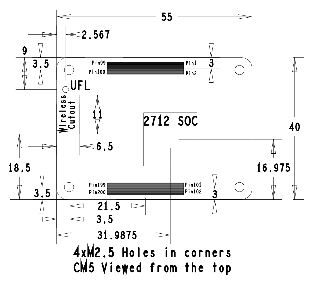
Dimensions
Core Board Size
Baseboard Size
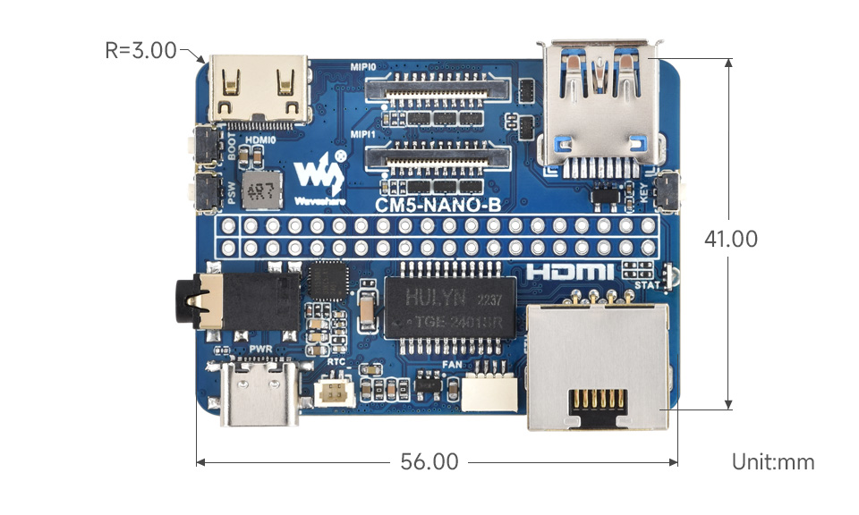
Image Flashing
How to Flash
Enter burning mode
1. The onboard BOOT button, you can press the BOOT button before powering on, and connect to the computer through Type C to let the device enter the flashing mode
Click here for EMMC version
Click here for LITE version
PCIe
Mount
1. Enable PCIE interface
Add in/boot/firmware/config.txt (this step is not required by default and can be skipped):
dtparam=pciex1
2. PCIE is gen2 by default, if you need to enable PCIE gen3, then add following to /boot/firmware/config.txt:
dtparam=pciex1_gen=3
3. For PCIe module drivers, please refer to the corresponding Wiki
Fan Control
The PI5 fan defaults to starting when the temperature reaches 50 degrees. If you want to control it at other temperatures, you can do so by adding specific content to /boot/firmware/config.txt, for example:
dtparam=fan_temp0=36000,fan_temp0_hyst=2000,fan_temp0_speed=90
dtparam=fan_temp1=40000,fan_temp1_hyst=3000,fan_temp1_speed=150
dtparam=fan_temp2=52000,fan_temp2_hyst=4000,fan_temp2_speed=200
dtparam=fan_temp3=58000,fan_temp3_hyst=5000,fan_temp3_speed=255
Among them:
fan_temp0/1/2/3               Indicates the temperature (36000 means 36℃)

fan_temp0/1/2/3_speed  Indicates the corresponding rotational speed (value up to 255)

fan_temp0/1/2/3_hyst      Indicates the hysteresis temperature
For more details, refer to here
Notice: There are only 4 temperatures, 0, 1, 2 and 3, and it's not possible to set other temperatures. The hysteresis temperature must not exceed the step range between two temperatures
MIPI
Support dual MIPI, customers can freely choose CSI or DSI connections
The DSI screen is 800x480 resolution screen by default, please refer to the corresponding WIKI for other resolution screens
DSI
First confirm if the screen resolution is 800x480. This driver only supports DSI resolutions of 800x480.
#Add the following to the config.txt file:
sudo nano /boot/firmware/config.txt
#DSI1
dtoverlay=vc4-kms-dsi-7inch,dsi0
#DSI0
dtoverlay=vc4-kms-dsi-7inch,dsi1
CSI
| Mode | CAM0 setup statement | CAM1 setup statement |
|---|---|---|
| OV9281 | dtoverlay=ov9281,cam0 | dtoverlay=ov9281,cam1 |
| IMX290/IMX327 | dtoverlay=imx290,clock-frequency=37125000,cam0 | dtoverlay=imx290,clock-frequency=37125000,cam1 |
| IMX378 | dtoverlay=imx378,cam0 | dtoverlay=imx378,cam1 |
| IMX219 | dtoverlay=imx219,cam0 | dtoverlay=imx219,cam1 |
| IMX477 | dtoverlay=imx477,cam0 | dtoverlay=imx477,cam1 |
| IMX708 | dtoverlay=imx708,cam0 | dtoverlay=imx708,cam1 |
Allow one connection to DSI and one connection to CSI, for example, use IMX219 to connect to MIPI1
For example, if you want to connect a DSI display to MIPI0, add the following to the config.txt file
dtoverlay=imx219,cam1
dtoverlay=vc4-kms-dsi-7inch,dsi0

sudo reboot
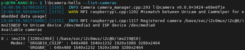
Test Camera
- Enter the camera detection command, and you can see that the camera has been detected
libcamera-hello --list-cameras
- Display the camera screen to the desktop
libcamera-hello -t 0
- Take a photo
libcamera-jpeg -o test.jpg
- Record a 10s video
libcamera-vid -t 10000 -o test.h264
Other commands
Check if the camera is detected
libcamera-hello --list-cameras
Open the corresponding camera
libcamera-hello  --camera 1
libcamera-hello  --camera 0
Take a photo
libcamera-jpeg -o test.jpg
#You can add --camera to specify the camera
Real-Time Clock (RTC)
There is no battery by default, and an additional RTC battery is required
Software Debugging
The default device is /dev/rtc0
Regarding time, by inputting "date" in the command line, you can see the current time. Connecting the Raspberry Pi system to the network will automatically synchronize the time. If the default RTC device is connected and functioning properly, the RTC time will be updated after the automatic network synchronization
sudo hwclock -r Read the RTC time, if there are multiple RTC devices, you can use -f to select the corresponding devices (for example: sudo hwclock -f /dev/rtc1 -r)
Hwclock
System clock -> Hardware clock (RTC)
sudo hwclock -w
Synchronize hardware clock (RTC) -> System clock
sudo hwclock  -s
 #Need to turn off the network, or disable network time synchronization, otherwise it will be changed back
Set the hardware clock time (RTC):
sudo hwclock --set --date="9/8/2023 16:45:05"View the hardware clock (RTC)
sudo hwclock -r
Show version information.
sudo hwclock --verbose
Automated Wakeup
To support a low-power mode for wake-up alarms, add the configuration:
sudo -E rpi-eeprom-config --edit
#Add the following 2 lines
POWER_OFF_ON_HALT=1
WAKE_ON_GPIO=0
#Restart the device after adding (if you connect to the serial port log, you can see that there are update related logs)
sudo reboot
#You can use the following methods to test the function:
echo +600 | sudo tee /sys/class/rtc/rtc0/wakealarm
sudo halt  or  sudo poweroff
#10 minutes later, it will be awakened and restarted
RTC Battery Charging
Note: Before adding this, make sure your RTC battery allows charging and check the maximum allowable voltage
sudo nano /boot/firmware/config.txt
#Add
dtparam=rtc_bbat_vchg=3000000
#Among these, 3,000,000 represents the maximum voltage. Charging will stop when it reaches 3V, and the charging will restart with a trickle charge when the voltage drops below 3V
USB
The onboard USB interface is USB3.2 Gen2 interface, and the speed is not shared (5Gbps rate can be at the same time)
The USB cable interface is USB 2.0, with a shared speed of 480Mbps
The total current is limited to 2A
Audio
Onboard USB audio interface and 3.5mm headphone jack with microphone support
Work with Raspberry Pi OS
Check playback: aplay -l
pi@raspberrypi:~$ aplay -l
**** List of PLAYBACK Hardware Devices ****
card 2: Device [USB PnP Audio Device], device 0: USB Audio [USB Audio]
  Subdevices: 1/1
  Subdevice #0: subdevice #0
Check recording: arecord -l
pi@raspberrypi:~$ arecord -l
**** List of CAPTURE Hardware Devices ****
card 2: Device [USB PnP Audio Device], device 0: USB Audio [USB Audio]
  Subdevices: 1/1
  Subdevice #0: subdevice #0
Record Test
sudo arecord -f S32_LE -Dplughw:2,0 | aplay -Dplughw:2,0
When the program runs, you will hear the sound collected by the microphone through the headphones or speaker. Please note that the speaker should not be placed too close to the microphone, as this may cause resonance and result in whistling.
The card 2 output by aplay-l is the sound card number, device is the device number
-Dplughw: 2,0 means specifying sound card 2 device 0
Record
sudo arecord -D hw:2,0 -f S16_LE -r 16000 -c 2 test.wav
test.wav is the name of the file generated by the recording.
Playback
sudo aplay -Dhw:2 test.wav
Play the audio you just recorded
The aplay only supports music in wav, in fact there are more music in MP3 format. You need to install:
sudo apt-get install mpg123
sudo mpg123 music.mp3
Please note that music.mp3 needs to be replaced with your MP3 music.
Adjust Volume
The default volume is relatively low
sudo alsamixer
If the sound card is not set as the default sound card, you need to press F6 to select the sound card device.
Button
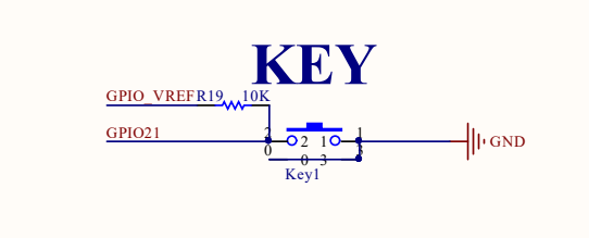
The user KEY button uses GPO21 with pull-up resistor
Resources
Datasheets and Schematic Diagram
CM5 Core board datasheet
CM5 Core board 3D
CM5 Core introduction
CM5-NANO-B Schematic diagram
CM5-NANO-B 3D
Related Links
FAQ
Question: Can the old versions of the Raspberry Pi operating system be used with CM5?
CM5 requires the latest version of Raspberry Pi OS Bookworm (2024-11-19 or later).
Support
Monday-Friday (9:30-6:30) Saturday (9:30-5:30)
Mobile: +86 13434470212
Email: services01@spotpear.com