


- sales/support
Google Chat:---
- sales
+86-0755-88291180
- sales01
sales@spotpear.com
- sales02
dragon_manager@163.com
- support
tech-support@spotpear.com
- CEO-Complaints
zhoujie@spotpear.com
- Only Tech-Support
WhatsApp:13246739196
- Purchase/Shipping/Refund
WhatsApp:13424403025
MPS2280-POE User Guide
I. Introduction
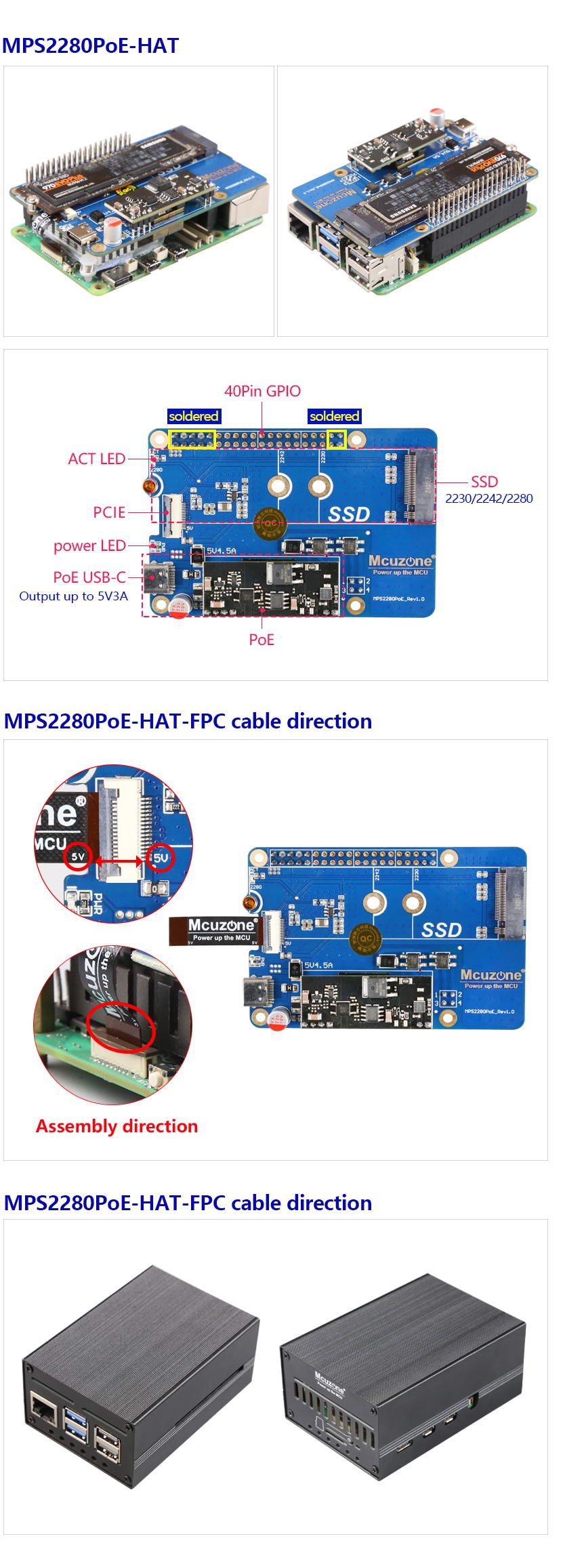
The MPS2280-PoE is a PoE-powered SSD expansion board designed for the Raspberry Pi 5, featuring voltage and current monitoring functions. It supports SSDs in sizes 2230, 2242, and 2280. The system can boot from the SSD, or from a TF card with the SSD used only for storage.
II. Hardware Resources
III. System flashing and configuration
1. Boot from a TF card
At this time, the SSD is used for storage purposes only. Use the Raspberry Pi Imager to write the image, select the Raspberry Pi 5 device, and use the image 2024-07-04-raspios-bookworm-arm64.img.xz (Raspberry Pi OS) or ubuntu-24.04-preinstalled-desktop-arm64+raspi.img.xz (Ubuntu system) for this document.
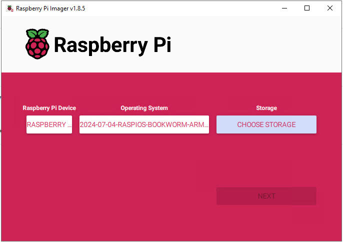
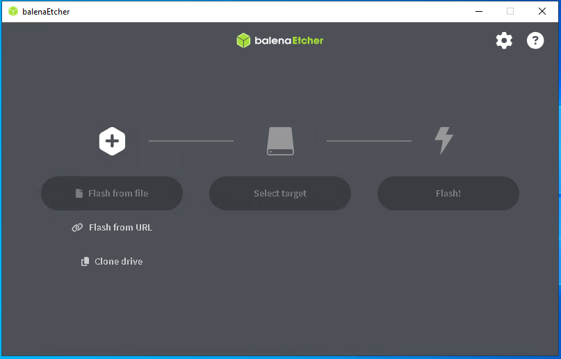
balenaEtcher can also be used to flash the image.
2. Boot from the SSD
You need to remove the SSD from the expansion board, insert it into an M.2 (PCIe protocol) to USB card reader, connect it to the PC, and use the same method as flashing an image to a TF card to flash the system image to the SSD. Then remove the SSD, and reinsert it into the expansion board.
IV. Demonstration of Voltage and Current Monitoring Function(INA219)(Only support MPS2280i-PoE)
1. Enable I2C
Method 1: Using the command line.
Input sudo raspi-config in the Raspberry Pi OS's terminal,Select the corresponding options according to the picture below:

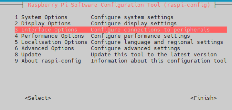
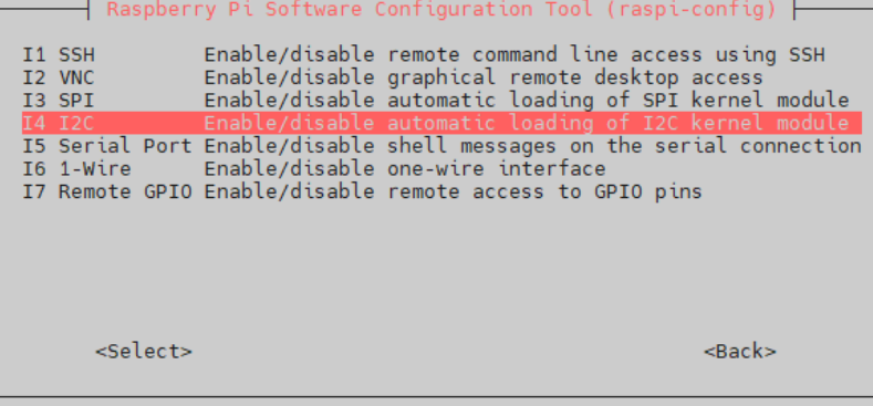
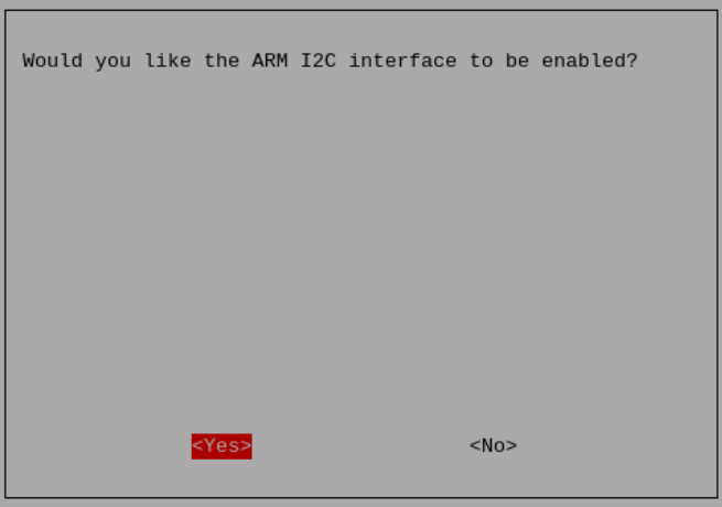
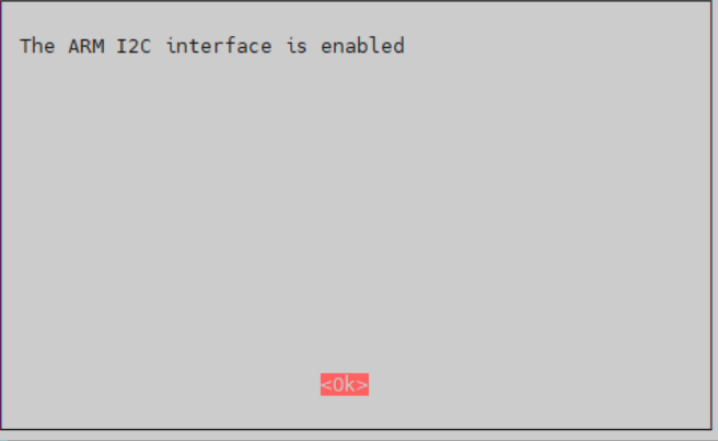
Enable the I2C in sequence, then restart the Raspberry Pi.
Method 2: Using the GUI.
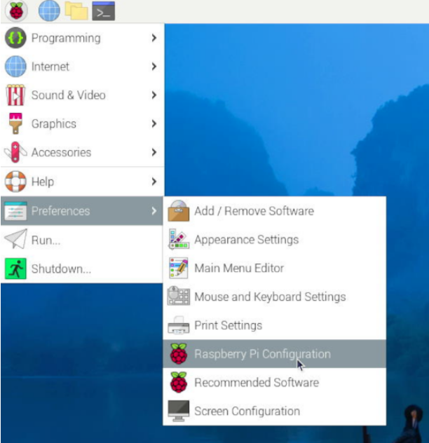

Enable the I2C in sequence, then restart the Raspberry Pi.
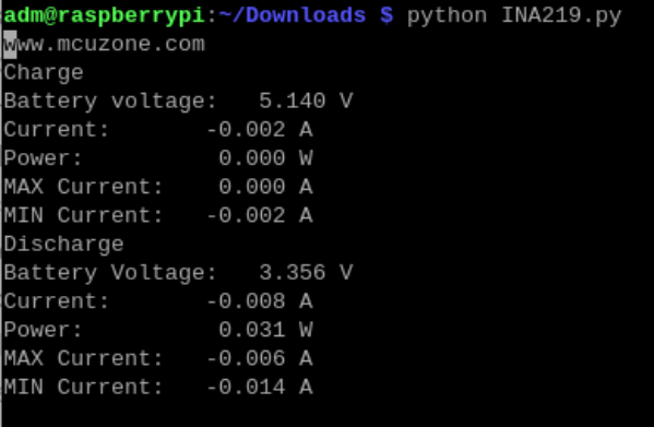
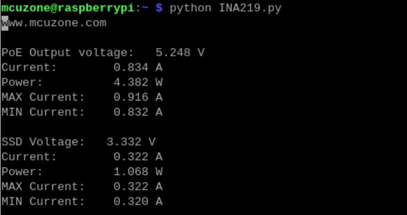
2. Run a Python script to measure voltage and current.
After the system restarts, copy the python script (INA219.py) which provided by our company into the Raspberry Pi operating system. Execute the file using the command python INA219.py to monitor voltage and current in real-time.
Download address for python script (need decompression):
http://www.mcuzone.com/wiki/0002_MPS2280iPoE/INA219.zip
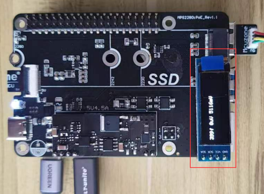
V. Demonstration of OLED screen usage(Only support MPS2280i-PoE)
1. Demonstration of OLED Screen usage on the Raspberry Pi OS
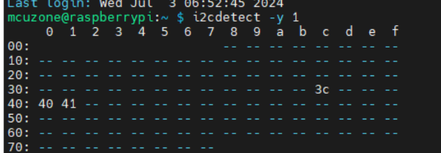
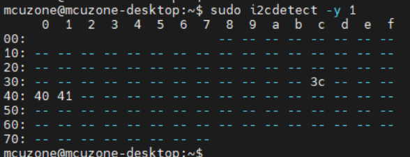
1) Confirm that the Raspberry Pi's I2C is enabled and the LCD screen is recognized at 0x3c.
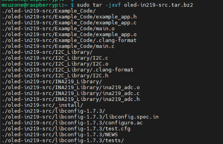
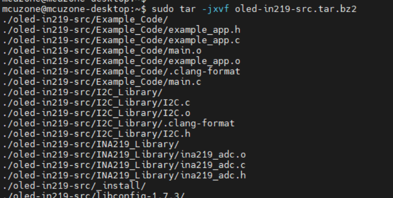
2) Copy the source package into the Raspberry Pi system and unzip it:
sudo tar -jxvf oled-in219-src.tar.bz2
Download address for the source package:
http://www.mcuzone.com/wiki/0002_MPS2280iPoE/oled-in219-src.tar.bz2
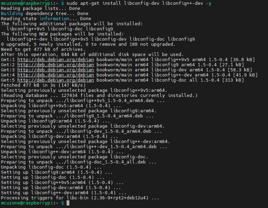
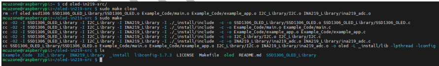
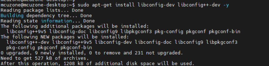
3) Install dependency files:sudo apt-get install libconfig-dev libconfig++-dev -y
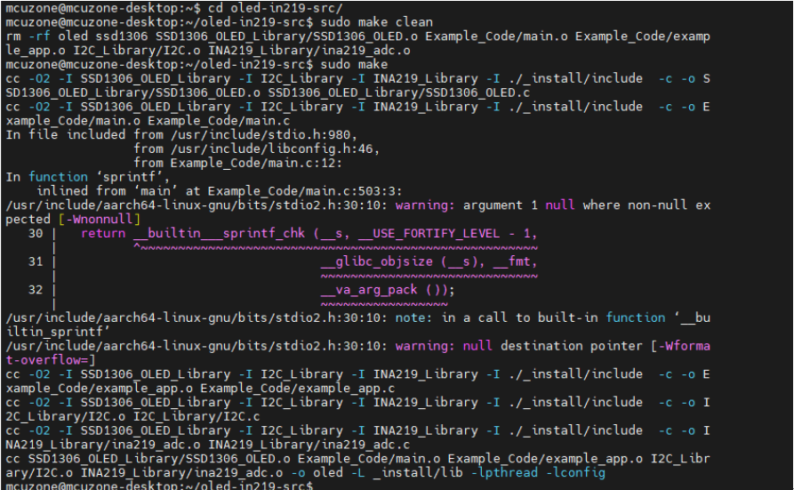
4) Enter the oled-in219-src directory and execute the commands sudo make clean and sudo make in sequence. After a successful compilation, an executable file named "oled" will be generated.
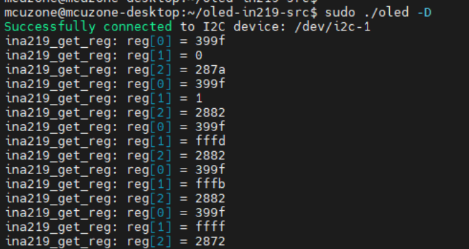
5) Run ./oled -D after Compilation:
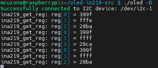
At the same time, the corresponding display will also be output on the OLED screen of the expansion board.
2. Demonstration of OLED Screen usage on the Ubuntu system
1) Confirm that the Raspberry Pi's I2C is enabled and the LCD screen is recognized at 0x3c.
Ubuntu system requires the installation of I2C tools manually.(sudo apt install i2c-tools)。
2) Copy the source package into the Raspberry Pi system and unzip it:
sudo tar -jxvf oled-in219-src.tar.bz2
Download address for the source package:
http://www.mcuzone.com/wiki/0002_MPS2280iPoE/oled-in219-src.tar.bz2
3) Install dependency files:sudo apt-get install libconfig-dev libconfig++-dev -y
4) Enter the oled-in219-src directory, then execute the following steps:
sudo apt install make
sudo apt install gcc
sudo make clean
sudo make
After a successful compilation, an executable file named "oled" will be generated.
Run ./oled -D after Compilation:
At the same time, the corresponding display will also be output on the OLED screen of the expansion board.
VI. POE function introduction
VII. POE output test (Only for MPS2280i-PoE)
7.1 Hardware connection
The MPS2280i-PoE expansion board supports POE input and ensures support for 5V4.5A output. We insert the POE output Ethernet port into the Raspberry Pi's built-in RJ45 Ethernet port, and the load is plugged into the USB-Type C port on the expansion board, thus completing the hardware connections.
7.2 View output status
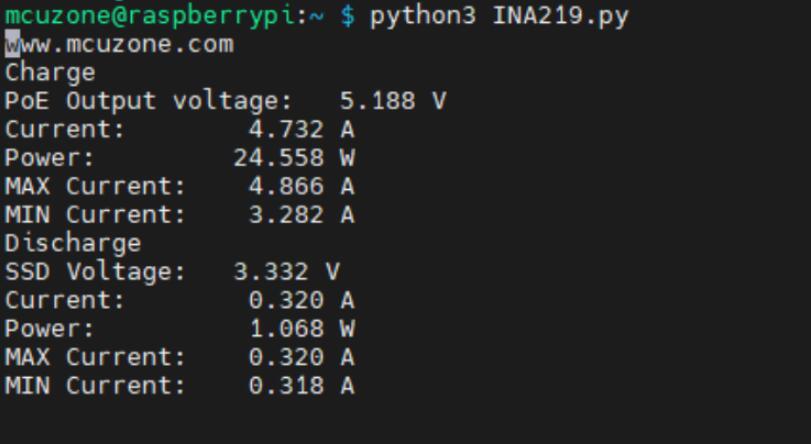
Turn on the PoE power supply, and enter the Raspberry Pi OS. The output monitoring software used here is the Python script from Chapter 4 (INA219.py). Following the method described in Chapter 3, navigate to the directory where INA219.py is located and enter python INA219.py. Then, you will be able to see the current output status.
We turn on each load one by one, and we can see that the output voltage stabilizes at around 5.2V. The output current continuously increases, eventually reaching around 4.7A, which meets the rated 5V 4.5A output standard.
After-sales
Monday-Friday (9:30-6:30) Saturday (9:30-5:30)
Email: services01@spotpear.com
[Tutorial Navigation]
- I. Introduction
- II. Hardware Resources
- III. System flashing and configuration
- IV. Demonstration of Voltage and Current Monitoring Function(INA219)(Only support MPS2280i-PoE)
- V. Demonstration of OLED screen usage(Only support MPS2280i-PoE)
- 1. Demonstration of OLED Screen usage on the Raspberry Pi OS
- 2. Demonstration of OLED Screen usage on the Ubuntu system
- VI. POE function introduction
- VII. POE output test (Only for MPS2280i-PoE)
- After-sales