


- sales/support
Google Chat:---
- sales
+86-0755-88291180
- sales01
sales@spotpear.com
- sales02
dragon_manager@163.com
- support
tech-support@spotpear.com
- CEO-Complaints
zhoujie@spotpear.com
- Only Tech-Support
WhatsApp:13246739196
- Purchase/Shipping/Refund
WhatsApp:13424403025
Lichee-Tang-Primer-20K-FPGA-Unboxing
【Dock ext-board】
】Matters need attention
Here are matters need attention, to avoid spending much time dealing with trouble and fail at last.
[] Enable Core Board
For 20K Dock kits, it's necessary to enable the core board before using debugger debug the chip, just put the 1 switch on the dip switch down, otherwise LED0 and LED1 are on and core board dose not work.
[] Device not work
We have inserted the Core Board into Dock ext-board before delivery, but sometimes we need remove the Core board for some reasons, and after reinserting the Core Board into Dock ext-board, they don't work.
The correct connection steps is to insert the Core board into the ext-board at an Angle roughly as shown in the left figure below. Make sure that the Core board inserted diagonally from above is in uniform contact with the ext-board, which can be judged by the degree of uniformity of the exposed gold finger.
Then gently press the tilted end, you can hear a sound of the Core board being fixed by the ext-board slot.
If you find it difficult to press the tilted end, you can try to polish both sides of the Core board slightly to eliminate the size error caused by the production process.
Just polish the two sides of the red box in the figure above to reduce the difficulty of inserting.
[] Hardware version introduction
For Dock ext-board, we can know the version of our board from the mark in the following picture.
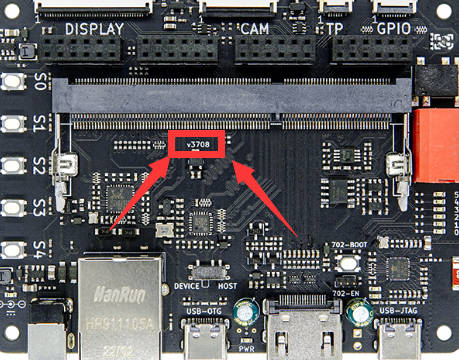
From the figure we can know the version of this board is V3708.
Here are their errors.
-> V3708
LED2 and LED3 are marked wrong, thay should be:
| Name | Correct mask | Wrong mask |
|---|---|---|
| LED2 | N16 | B14 |
| LED3 | N14 | N16 |
】Start to use
For Dock ext-board, the following things can be done with default firmware.
- Press key S0, reset the RGB screen, camera, HDMI signal. And LED3, LED4, LED5 are on.
- Press key S0 to key S5, the state of LED0, lED1, LED2 changes.
- Connect OV5640 camera and 4.3 inch RGB screen with Dock ext-board (Make sure power is off while connecting), the screen display the picture captured by camera. If the screen displays not well, try to press key S0, this will synchronize the camera picture and screen content.
】Questions
Visit Questions for more solvements
【Lite ext-board】
】Hardware version introduction
For Lite ext-board,we can know the version of our board from the mark in the following picture.
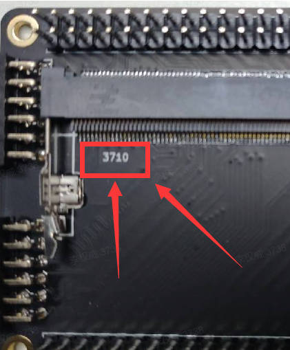
From the figure we can know the version of this board is 3710.
Here are their errors.
[] 3710
The mask between R8 and P9 is P8. Refer to the left top of the right picture.
】Questions
Visit Questions for more solvements
