


- sales/support
Google Chat:---
- sales
+86-0755-88291180
- sales01
sales@spotpear.com
- sales02
dragon_manager@163.com
- support
tech-support@spotpear.com
- CEO-Complaints
zhoujie@spotpear.com
- Only Tech-Support
WhatsApp:13246739196
- Purchase/Shipping/Refund
WhatsApp:13424403025
- HOME
- >
- ARTICLES
- >
- Common Moudle
- >
- ESP
ESP32-S3-LCD-7B User Guide
Introduction
Introduction
This is a low-cost, high-performance MCU development board designed by Waveshare. It supports 2.4GHz WiFi and BLE 5, integrates high-capacity Flash and PSRAM, and has a 7inch wide capacitive touch LCD screen on board to smoothly run GUI interface programs such as LVGL. It combines a variety of peripheral interfaces (e.g., CAN, I2C, RS485, etc.) to quickly develop applications such as HMIs for ESP32-S3. With a wide range of functions and interfaces, it can meet power consumption requirements in Internet of Things (IoT), mobile devices, smart home and other applications.
Features
- Equipped with high-performance Xtensa 32-bit LX7 dual-core processor, up to 240MHz main frequency
- Supports 2.4GHz Wi-Fi (802.11 b/g/n) and Bluetooth 5 (BLE), with onboard antenna
- Built-in 512KB SRAM and 384KB ROM, with onboard 16MB Flash and 8MB PSRAM
- Onboard 7inch LCD display, 1024×600 resolution, 65K color
- Supports capacitive touch control via I2C interface (optional), with 5-point touch, and supports interrupts
- Onboard CAN, RS485, I2C interface and TF card slot, integrates full-speed USB
- Onboard LED indicators for indicating the power and battery charging status
- Supports adjusting the backlight brightness and reading the current battery voltage
- Supports flexible clock, precise control with individual power settings for modules, enabling low-power modes for multiple scenarios
Onboard Resources
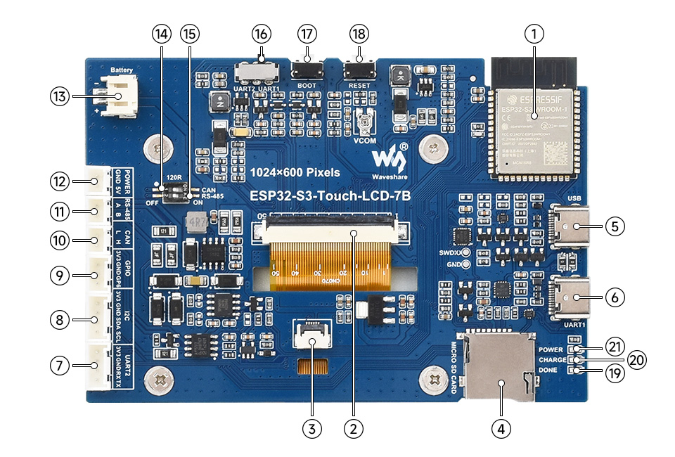
1. ESP32-S3-WROOM-1-N16R8 module 2. Display terminal 3. Touchscreen terminal 4. TF card slot 5. USB Type-C port 6. USB TO UART Type-C port 7. UART terminal 8. I2C terminal 9. Sensor terminal 10. CAN terminal 12. 5V output | 13. 3.7V single lithium battery PH2.0 socket 14. CAN termination resistor selection 15. RS485 termination resistor selection 16. UART selection 17. BOOT button 18. RESET button 19. DONE 20. CHARGE 21. POWER |
Pinouts
- LCD port: The port to connect the LCD cable
| ESP32-S3 | LCD | Description |
| GPIO0 | G3 | Green data 3rd place |
| GPIO1 | R3 | Red data 3rd place |
| GPIO2 | R4 | Red data 4th place |
| GPIO3 | VSYNC | Vertical synchronization signal |
| GPIO5 | DE | Data enable signal |
| GPIO7 | PCLK | Clock signal |
| GPIO10 | B7 | Blue 7th place |
| GPIO14 | B3 | Blue 3rd place |
| GPIO17 | B6 | Blue 6th place |
| GPIO18 | B5 | Blue 5th place |
| GPIO21 | G7 | Green 7th place |
| GPIO38 | B4 | Blue 4th place |
| GPIO39 | G2 | Green 2nd place |
| GPIO40 | R7 | Red 7th place |
| GPIO41 | R6 | Red 6th place |
| GPIO42 | R5 | Red 5th place |
| GPIO45 | G4 | Green 4th place |
| GPIO46 | HSYNC | Horizontal synchronization signal |
| GPIO47 | G6 | Green 6th place |
| GPIO48 | G5 | Green 5th place |
| IO EXTENSION | LCD | - |
| EXIO2 | DISP | Backlight enable pin |
| EXIO6 | LCD_VDD_EN | VCOM voltage enable pin |
- Touchscreen port: The port to connect the touch cable
| ESP32-S3 | Touch | Description |
| GPIO4 | TP_IRQ | Touch interrupt pin |
| GPIO8 | TP_SDA | Touch data pin |
| GPIO9 | TP_SCL | Touch clock pin |
| IO EXTENSION | Touch | - |
| EXIO1 | TP_RST | Touch reset pin |
- USB port: For power supply and flashing
| ESP32-S3 | USB | Description |
| GPIO19 | USB_DN | Data cable D- |
| GPIO20 | USB_DP | Data cable D+ |
| IO EXTENSION | USB | - |
| EXIO5 | USB_SEL | Pull down to USB mode, otherwise CAN mode |
- TF card slot: It is used to insert the TF card. The pin connections are shown in the table below.
| ESP32-S3 | TF | Description |
| GPIO11 | MOSI | TF card input pin |
| GPIO12 | SCK | TF card clock pin |
| GPIO13 | MISO | TF card output pin |
| IO EXTENSION | TF | - |
| EXIO4 | SD_CS | TF card enable pin, active low |
- RS485 port: The development board is equipped with an RS485 port, allowing direct connection for device communication, with automatic switching of the circuit's transmit and receive modes
| ESP32-S3 | RS485 | Description |
| GPIO16 | RS485_RXD | Data input |
| GPIO15 | RS485_TXD | Data output |
- CAN port: Implements the transmission and reception control, data analysis, acquisition and monitoring of the CAN bus network
| ESP32-S3 | CAN | Description |
| GPIO20 | CANTX | Data output |
| GPIO19 | CANRX | Data input |
| IO EXTENSION | CAN | - |
| EXIO5 | CAN_SEL | Pull up to CAN mode, otherwise USB mode |
- I2C port: ESP32-S3 provides multi-channel hardware I2C, currently using GPIO8 (SDA) and GPIO9 (SCL) pins for I2C bus
It connects peripherals such as IO expansion chip and touch screen via the I2C port.
| ESP32-S3 | I2C | Description |
| GPIO8 | SDA | I2C data pin |
| GPIO9 | SCL | I2C clock pin |
- PH2.0 battery socket: The development board uses a high-efficiency charge/discharge management chip CS8501, which can boost a single lithium battery to 5V, the current charging current is 580mA, and the user can change the charging current by replacing the R45 resistor, please refer to ESP32-S3-Touch-LCD-7B Schematic for details.
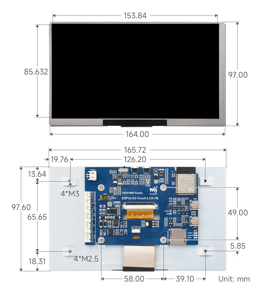
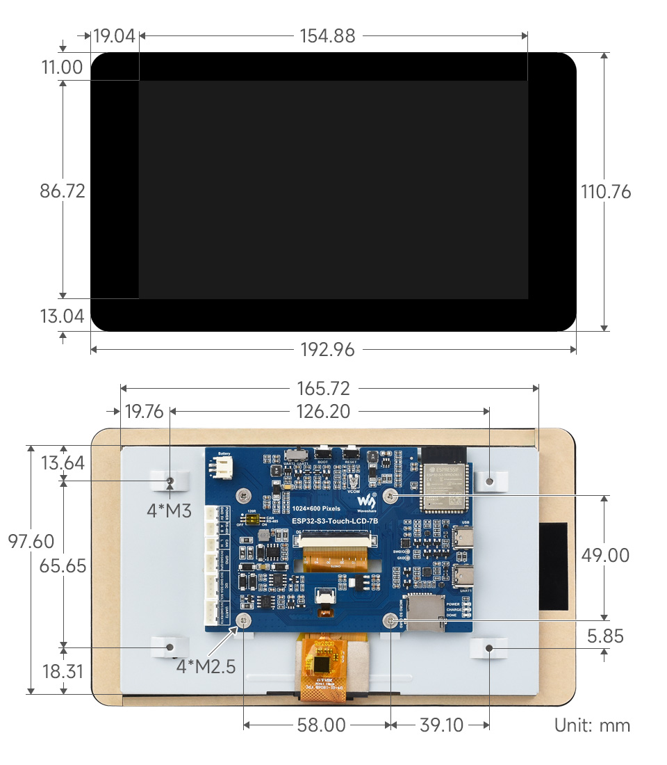
Dimensions
Without Touch Version
With Touch Version
Specifications
| Basic parameters | |
|---|---|
| Processor | High-performance 32-bit Xtensa LX7 dual-core processor with a frequency up to 240MHz |
| Wifi/Bluetooth | Supports 2.4 GHz Wi-Fi (802.11 b/g/n) and Bluetooth 5 (LE) with onboard antennas |
| Flash | 16MB Flash |
| PSRAM | 8MB PSRAM |
| Power supply range | TypeC 5V |
| Screen parameters | |
| Resolution | 1024 x 600 |
| Display interface | RGB |
| Display panel | IPS |
| Viewing angle | 170° |
| Screen brightness | 235 cd/m² |
| Touch type | Capacitive |
| Touch panel | toughened glass |
| Peripheral interface | |
| Communication interface | CAN, RS485, I2C, USB |
| Other | |
| Power consumption | 5V 350mA |
| Operating temperature | 0℃ ~ 65℃ |
| Product size (L×W) | Non-touch version: 164×97mm Touch version: 192.96×110.76mm |
Usage Instructions
Currently there are three development tools and frameworks, Arduino IDE, ESP-IDF and PlatformIO, providing flexible development options, you can choose the right development tool according to your project needs and personal habits.
Development Tool
| Arduino IDEArduino IDE is an open source electronic prototyping platform, convenient and flexible, easy to get started. After a simple learning, you can start to develop quickly. At the same time, Arduino has a large global user community, providing an abundance of open source code, project examples and tutorials, as well as rich library resources, encapsulating complex functions, allowing developers to quickly implement various functions. |
| ESP-IDFESP-IDF, or full name Espressif IDE, is a professional development framework introduced by Espressif Technology for the ESP series chips. It is developed using the C language, including a compiler, debugger, and flashing tool, etc., and can be developed via the command lines or through an integrated development environment (such as Visual Studio Code with the Espressif IDF plugin). The plugin offers features such as code navigation, project management, and debugging, etc. |
| PlatformIOPlatformIO is a cross-platform, cross-architecture, multi-framework professional tool for embedded system engineers and software developers who write applications for embedded products. |

Each of these three development approaches has its own advantages, and developers can choose according to their needs and skill levels. Arduino and PlatformIO (faster compilation speed) are suitable for beginners and non-professionals because they are easy to learn and quick to get started. ESP-IDF is a better choice for developers with a professional background or high performance requirements, as it provides more advanced development tools and greater control capabilities for the development of complex projects.
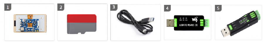
Components Preparation
- ESP32-S3-Touch-LCD-7B x1
- TF card x 1 (Not required, example required)
- USB cable (Type-A male to Type-C male) x1
- USB TO RS485 bidirectional converter x1 (Not required, example required)
- USB to CAN adapter analyzer x1 (Not required, example required)
Precautions
- The development board has an onboard automatic download circuit, the Type C port at the UART silk screen is used for program download and log printing. After downloading the program, press the RESET button to run the program
- Please pay attention to the PCB antenna area when using, and avoid attaching other metals or plastic parts to the PCB antenna
- The TF card uses SPI/MMC to communicate, note that the SD_CS pin needs to be driven by the EXIO4 of the IO EXTENSION
- The development board uses PH2.0 header to lead out ADC, CAN, I2C, RS485, 5V peripheral pins, and connects sensor components using PH2.0 to 2.54mm male connector
- The CAN and RS485 peripherals use use a dip switch to connect the 120 ohm resistor by default, and NC can optionally cancel the termination resistor connection
- The 7inch screen occupies the vast majority of the GPIO, and the development board uses the chip to expand the IO for reset, backlight on/off, brightness adjustment, and battery voltage reading, etc.
- The development board uses USB to download the demo. If the port cannot be recognized, please enter boot mode (press and hold the boot button, then connect to the computer, and then release the boot button). After downloading the demo, press the RESET button to run the demo.
- Currently, under ESP-IDF v5.3, the average frame rate limit for running the LVGL benchmark demo with a single core is 17 frames per second, corresponding to an interface PCLK rate of 30 MHz). Before compilation, ESP32 and LVGL need to be configured through menuconfig:
CONFIG_FREERTOS_HZ=1000
CONFIG_ESP_DEFAULT_CPU_FREQ_MHZ_240=y
CONFIG_ESPTOOLPY_FLASHMODE_QIO=y
CONFIG_ESPTOOLPY_FLASHFREQ_120M=y [Need to be consistent with PSRAM]
CONFIG_SPIRAM_MODE_OCT=y
CONFIG_IDF_EXPERIMENTAL_FEATURES=y and CONFIG_SPIRAM_SPEED_120M=y [Need to be consistent with FLASH]
CONFIG_SPIRAM_FETCH_INSTRUCTIONS=y
CONFIG_SPIRAM_RODATA=y
CONFIG_ESP32S3_DATA_CACHE_LINE_64B=y
CONFIG_COMPILER_OPTIMIZATION_PERF=y
#The following LVGL configuration items are helpful for frame rate improvement (LVGL v8.3):
#define LV_MEM_CUSTOM 1 or CONFIG_LV_MEM_CUSTOM=y
#define LV_MEMCPY_MEMSET_STD 1 or CONFIG_LV_MEMCPY_MEMSET_STD=y
#define LV_ATTRIBUTE_FAST_MEM IRAM_ATTR or CONFIG_LV_ATTRIBUTE_FAST_MEM=y
- For detailed LCD and LVGL performance descriptions, please refer to Documentation
- PH2.0 lithium battery holder only supports a single 3.7V lithium battery, do not use multiple sets of battery packs to connect to charge and discharge at the same time, and it is recommended that the capacity of a single battery is less than 2000mAH
- ESP32-S3-Touch-LCD-7B occupies the following slave address, please do not use I2C devices with the same address:
    0  1  2  3  4  5  6  7  8  9  a  b  c  d  e  f
00: -  -  -  -  -  -  -  -  -  -  -  -  -  -  -  -
10: -  -  -  -  -  -  -  -  -  -  -  -  -  -  -  -
20: -  -  -  -  24 -  -  - -  -  -  -  -  -  -  -
30: -  -  -  -  -  -  -  -  -  -  -  -  -  -  -  -
40: -  -  -  -  -  -  -  -  -  -  -  -  -  -  -  -
50: -  -  -  -  -  -  -  -  -  -  -  -  -  -  5d -
60: -  -  -  -  -  -  -  -  -  -  -  -  -  -  -  -
70: -  -  -  -  -  -  -  -  -  -  -  -  -  -  -  -
Working with Arduino
This chapter introduces setting up the Arduino environment, including the Arduino IDE, management of ESP32 boards, installation of related libraries, program compilation and downloading, as well as testing demos. It aims to help users master the development board and facilitate secondary development.
Environment Setup
Download and Install Arduino IDE
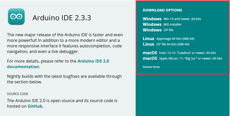
- Click to visit the Arduino official website, select the corresponding system and system bit to download The version of the Arduino IDE needs to be ≥ 1.8, and the path of installation must not be Chinese, otherwise there will be an error when compiling.
- Run the installer and install all by default
Install Arduino-ESP32
- Must first install the development board esp32-XIP-3.1.1.
- Only supports Install Offline.
- For the installation tutorial, please refer to esp32-XIP-3.1.1 Development board installation.
| Board name | Board installation requirement | Instruction |
|---|---|---|
| esp32-XIP-3.1.1 | "Install Offline" | The "esp32-XIP-3.1.1" board must be installed according to the installation tutorial |
Install Libraries
- When installing Arduino libraries, there are usually two ways to choose from: Install online and Install offline. If the library installation requires offline installation, you must use the provided library file
For most libraries, users can easily search and install them through the online library manager of the Arduino software. However, some open-source libraries or custom libraries are not synchronized to the Arduino Library Manager, so they cannot be acquired through online searches. In this case, users can only manually install these libraries offline. - For library installation tutorial, please refer to Arduino library manager tutorial
- ESP32-S3-Touch-LCD-7B library file is stored in the demo, click here to jump: ESP32-S3-Touch-LCD-7B Demo
| Library Name | Description | Version | Library Installation Requirement |
|---|---|---|---|
| lvgl | LVGL graphical library | v8.4.0 | "Install Offline" |
| lv_conf.h | LVGL configuration file | —— | "Install Offline" |
Run the First Arduino Demo
New Project
- Run the Arduino IDE and select
File->New Sketch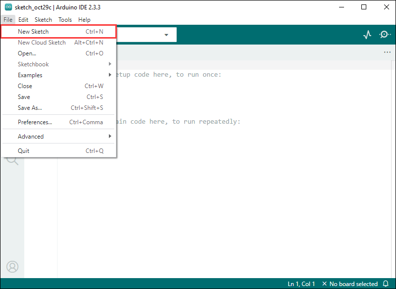
- Enter the code:
void setup() {
  // put your setup code here, to run once:
  Serial.begin(115200);
}

void loop() {
  // put your main code here, to run repeatedly:
  Serial.println("Hello, World!");
  delay(2000);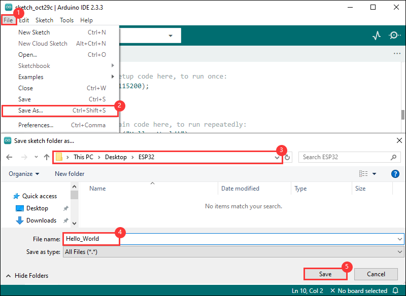
}- Save the project and select
File->Save As.... In the pop-up menu, select the path to save the project, and enter a project name, such as Hello_World, clickSave
Compile and Flash Demos
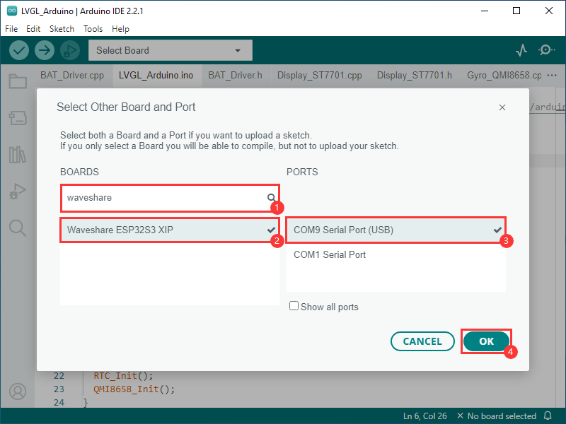
- Select the corresponding development board, take the ESP32S3 motherboard as an example:
①. Click to select the dropdown menu option Select Other Board and Port;
②. Search for the required development board model esp32s3 dev module and select;
③. Select COM Port;
④. Save the selection.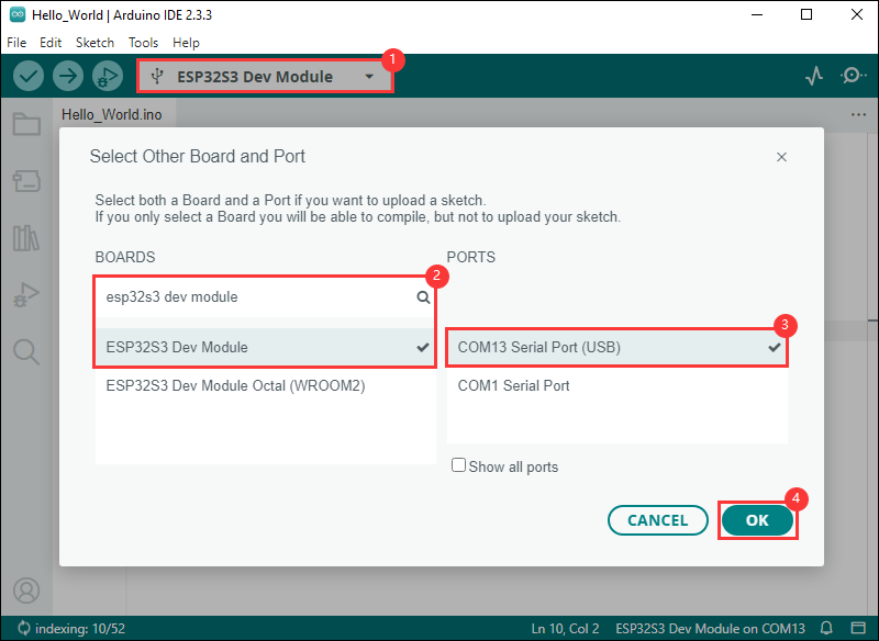
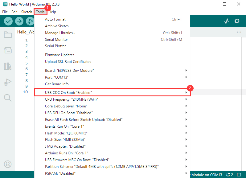
- If the ESP32S3 mainboard only has a USB port, you need to enable USB CDC, as shown in the following diagram:
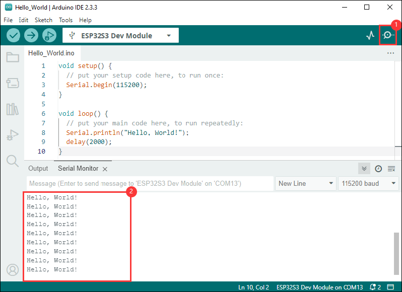
- Compile and upload the program:
①. Compile the program; ②. Compile and download the program; ③. Download successful.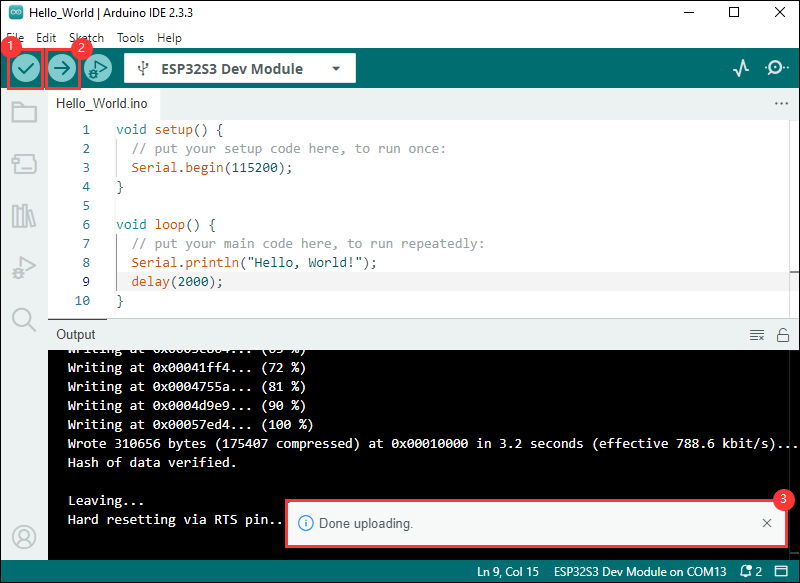
- Open the Serial Monitor window, and the demo will print "Hello World!" every 2 seconds, and the operation is as follows:
Demo
| Demo | Basic Description | Dependency Library |
|---|---|---|
| 01_GPIO | Test GPIO | - |
| 02_UART | Test UART | - |
| 03_I2C | Test I2C | - |
| 04_CAN | Test CAN | - |
| 05_RS485 | Test I2C | - |
| 06_LCD | Test display | - |
| 07_SD | Test TF card | - |
| 08_TOUCH | Test touchscreen | - |
| 09_DISPLAY_BMP | Display BMP images from the TF card on the screen | - |
| 11_WIFI_STA | Connect to the AP and display the IP | - |
| 12_WIFI_AP | Start AP and display the MAC address of connected devices | - |
| 13_LVGL_TRANSPLANT | Transplant LVGL | LVGL |
| 14_LVGL_BTN | Draw a button to control GPIO operation | LVGL |
| 15_LVGL_SLIDER | Draw a slider to control backlight and GPIO output, and simultaneously display battery voltage | LVGL |
- Demos 08, 09, 13, 14, and 15 can only be applied to boards with touch screens.
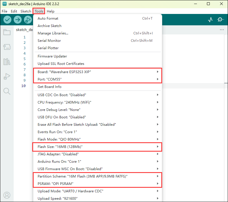
- Select the Waveshare ESP32S3 XIP model and port
01_GPIO
Hardware connection
- Connect the board to the computer using a USB cable
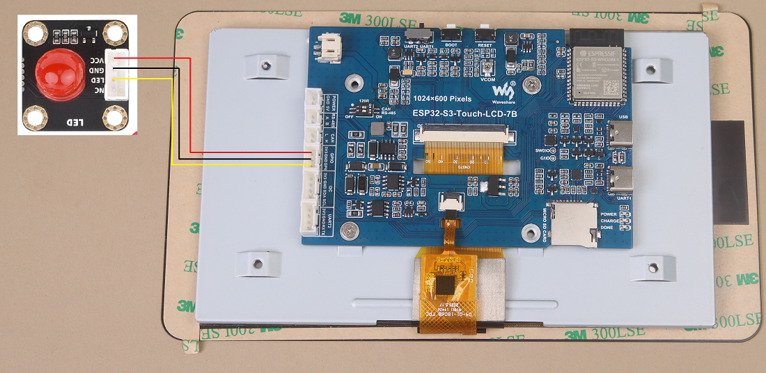
- Connect the LED module to the GPIO

Code analysis
setup():
setup() function initializes GPIO 6 and sets it to output mode.
loop():
loop() function is the main loop of the program, with the core functionality of repeatedly pulling the GPIO pin high or low to control the LED's on and off.
Demo flashing
- Select the Waveshare ESP32S3 XIP model and port
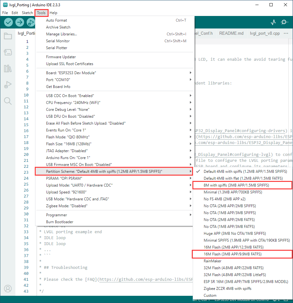
- Set development board parameters

- Flash the demo
Result demonstration
- The screen shows nothing, and the connected LED lights will turn on and off at a frequency of 1 Hz
02_UART
Hardware connection
- Connect the UART port of the board to the computer using a USB cable
Code analysis
setup():
setup function is primarily used for initializing serial communication
Use the UART.begin function to initialize serial port Serial , set the baud rate, data format, and specify the receive and transmit pins. Then, through a loop, ensure the serial port initialization is successful.
loop():
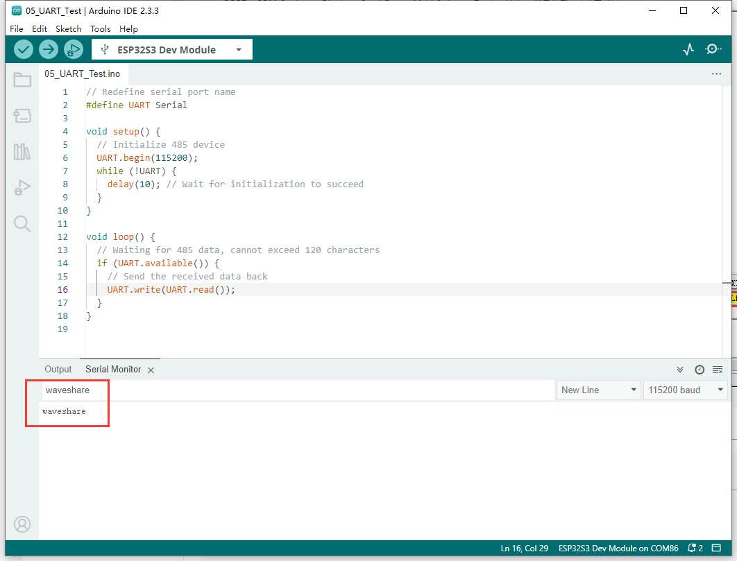
loop function is the main loop part of the program, and its main function is to implement simple UART communication data return
By checking whether there is data available at the serial port, if there is data, it reads a byte and sends it back immediately, so that the received UART data can be sent back intact
Demo flashing
- Select the Waveshare ESP32S3 XIP model and port
- Set development board parameters

- Flash the demo
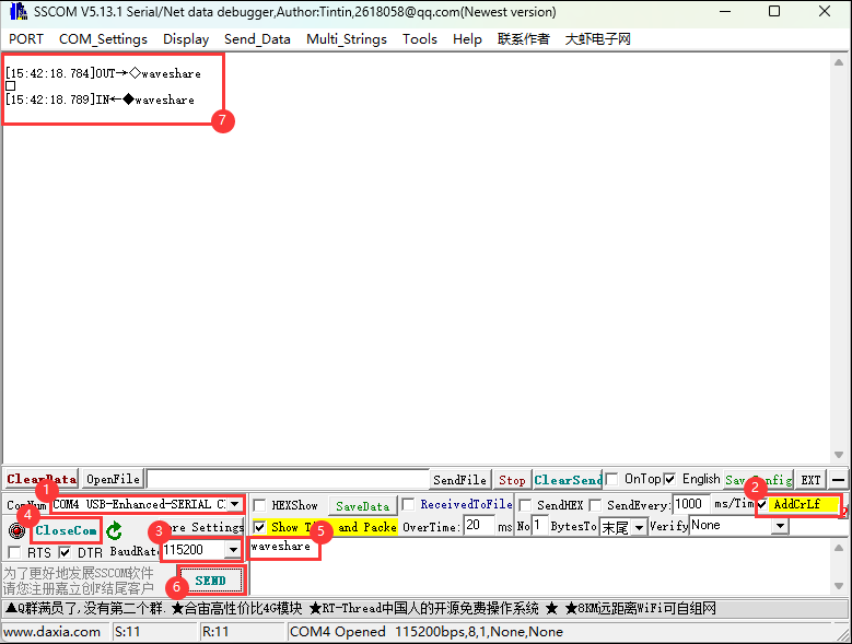
Result demonstration
- Open the serial port debugging assistant to send a message to the ESP32-S3-Touch-LCD-7B device, and the device will return the received message to the serial port debugging assistant

03_I2C
Hardware connection
- Connect the UART port of the board to the computer using a USB cable
Code analysis
setup():
setup() function initializes I2C and IO expansion.
DEV_I2C_Init():
DEV_I2C_Init() function initializes the I2C device
IO_EXTENSION_Init():
IO_EXTENSION_Init() function initializes IO extension.
loop():
loop() function is the main loop of the program, with the core functionality of controlling the IO expansion chip to repeatedly pull the DISP pin high or low, thereby controlling the screen backlight on and off.
IO_EXTENSION_Output(uint8_t pin, uint8_t value):
IO_EXTENSION_Output(uint8_t pin, uint8_t value) function controls the IO expansion chip to output a specified level.
Demo flashing
- Select the Waveshare ESP32S3 XIP model and port
- Set development board parameters

- Flash the demo
Result demonstration
- The screen backlight will turn on and off at a frequency of 1Hz
04_CAN
Hardware connection
- Connect the board to the computer using a USB cable
- Connect the development board to USB-CAN-A, as shown in the figure

Code analysis
setup():
setup() function initializes I2C, IO expansion, and CAN interface. Before initializing the CAN interface, it needs to control IO_EXTENSION_IO_5 to a high level; otherwise, the CAN interface will not work.
can_init(twai_timing_config_t t_config, twai_filter_config_t f_config, twai_general_config_t g_config):can_initfunction is mainly responsible for handling the initialization of TWAI (an interface similar to the CAN bus)
loop():
loop() function checks if any alarms occur. Read the triggered alerts by calling can_read_alerts and obtain the TWAI status information into alerts_triggered . Then, according to the different alarms triggered, perform corresponding processing. For example, if an error passive alarm, a bus error alarm, a transmission failure alarm, or a transmission success alarm is triggered, print the corresponding message and output some status information such as the bus error count, the number of messages to be sent, the transmission error counter, and the transmission failure counter.
- If the correct data is read, it will read the information and then send the data back unchanged.
Demo flashing
- Select the Waveshare ESP32S3 XIP model and port
- Set development board parameters

- Flash the demo
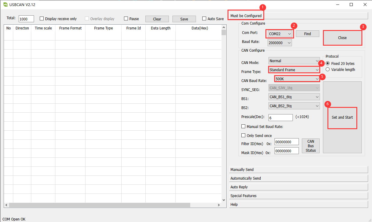
Result demonstration
- The screen will not display
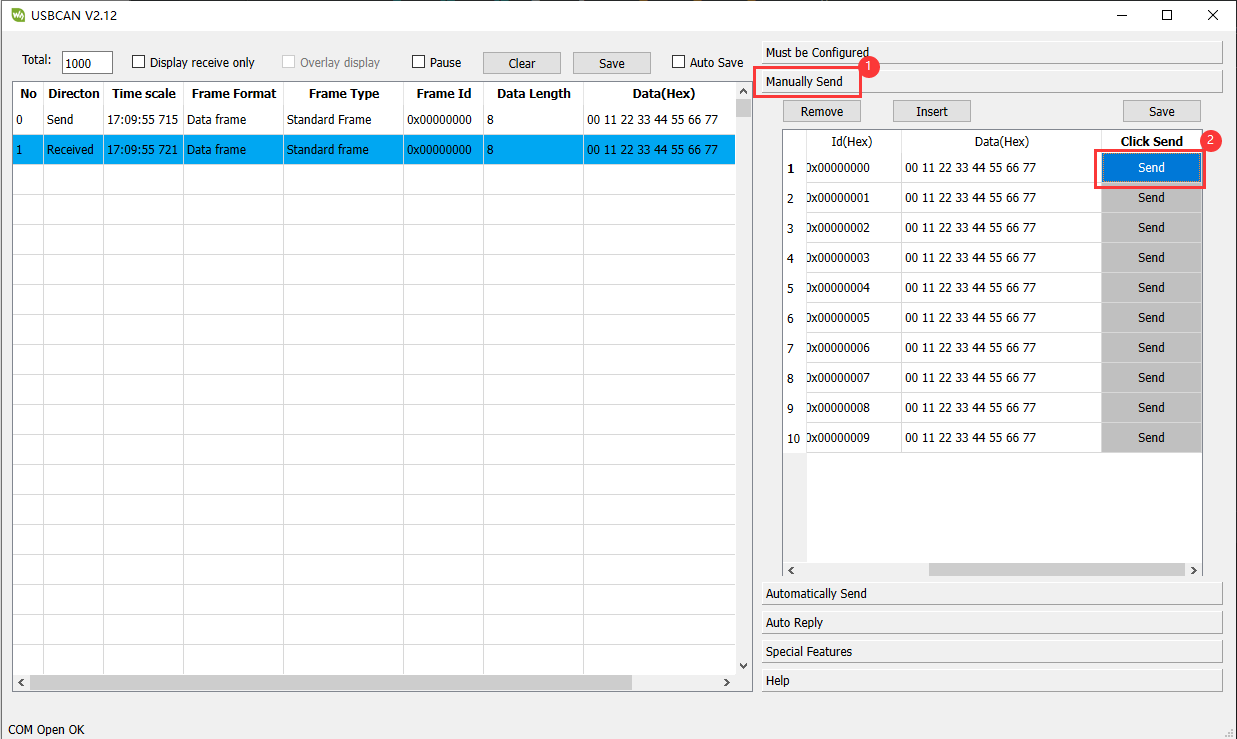
- After configuring USB-CAN-A_TOOL, start and send a CAN message to ESP32-S3-Touch-LCD-7B. You can see that ESP32-S3-Touch-LCD-7B returns the same message.

05_RS485
Hardware connection
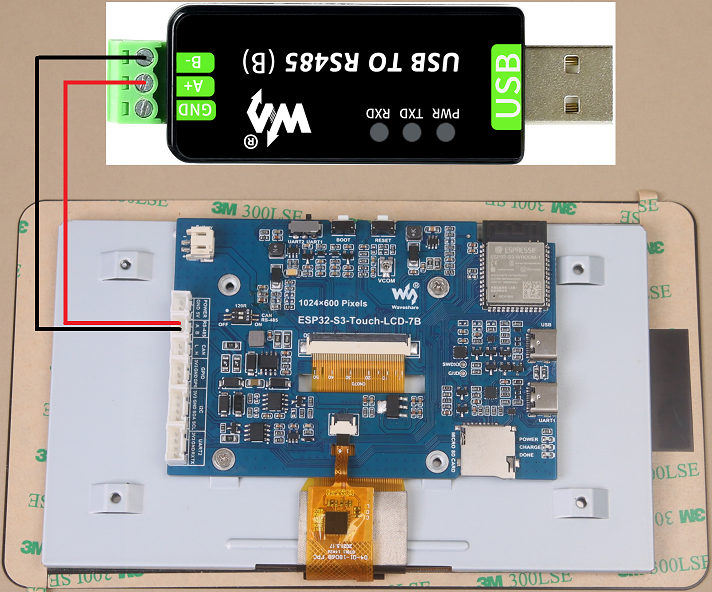
- Connect the board to the computer using a USB cable
- Connect the development board to USB to RS485 converter, as shown in the figure

Code analysis
setup():
setup function is primarily used for initializing serial communication
Use the RS485.begin function to initialize serial port Serial1, set the baud rate, data format, and specify the receive and transmit pins. Then, through a loop, ensure the serial port initialization is successful.
loop():
loop function is the main loop part of the program, and its main function is to implement simple 485 communication data return
By checking whether there is data available at the serial port, if there is data, it reads a byte and sends it back immediately, so that the received 485 data can be sent back intact
Demo flashing
- Select the Waveshare ESP32S3 XIP model and port
- Set development board parameters

- Flash the demo
Result demonstration
- Open the serial port debugging assistant to send a message to the ESP32-S3-Touch-LCD-7B device (the message must contain a newline, otherwise no data will be returned), and the device will return the received message to the serial port debugging assistant
06_LCD
Hardware connection
- Connect the board to the computer using a USB cable
Code analysis
setup():setupfunction mainly performs a series of initialization operations and tests on the display- First, it initializes I2C, IO expansion, and the RGB LCD, and then turns on the backlight. Then create a buffer to store the image, initialize the GUI image data, set the current image format and rotation angle, and finally start controlling the screen to display the corresponding interface.
- During the test, you can set the rotation angle yourself (in line 13) to realize the display of different angles.
- First, it initializes I2C, IO expansion, and the RGB LCD, and then turns on the backlight. Then create a buffer to store the image, initialize the GUI image data, set the current image format and rotation angle, and finally start controlling the screen to display the corresponding interface.
waveshare_esp32_s3_rgb_lcd_init():waveshare_esp32_s3_rgb_lcd_initfunction mainly initializes the RGB LCD.
wavesahre_rgb_lcd_bl_on():wavesahre_rgb_lcd_bl_onfunction mainly turns on the LCD backlight.- For more functions, they are also explained in the example, which can be viewed directly in the example.
Demo flashing
- Select the Waveshare ESP32S3 XIP model and port
- Set development board parameters

- Flash the demo
Result demonstration
- The ESP32-S3-Touch-LCD-7B will first display the RGB565 color box, then show the pattern and text, and finally display the image.
07_SD
Hardware connection
- Connect the board to the computer using a USB cable
- Connect the TF card to ESP32-S3-Touch-LCD-7B
Code analysis
setup():
setup function mainly performs a series of initialization operations and tests on the TF card, and displays relevant information on the screen.
sd_mmc_init():
sd_mmc_init function mainly initializes and mounts the TF card.
read_sd_capacity(uint64_t *total_capacity, uint64_t *available_capacity):
read_sd_capacity function primarily reads the memory information of the TF card.
Demo flashing
- Select the Waveshare ESP32S3 XIP model and port
- Set development board parameters
- Flash the demo
Result demonstration
- Running Effect: ESP32-S3-Touch-LCD-7B will display TF card information, if not, it will display "SD Card Fail!”
08_TOUCH
Hardware connection
- Connect the board to the computer using a USB cable
Code analysis
setup():
setup function mainly performs a series of initialization operations and tests on the touch screen, and displays it on the screen.
touch_gt911_init():
touch_gt911_init function mainly initializes the touchscreen.
touch_gt911_read_point(uint8_t max_touch_cnt) :
touch_gt911_read_point function mainly reads the current coordinate point and can recognize up to 5 touch points.
Demo flashing
- Select the Waveshare ESP32S3 XIP model and port
- Set development board parameters

- Flash the demo
Result demonstration
- When touching the screen, points will be displayed on the screen, and touching five points at the same time will display five different colored points.
09_DISPLAY_BMP
Hardware connection
- Connect the board to the computer using a USB cable
- Save the images in the directory to the TF card and connect it to ESP32-S3-Touch-LCD-7B
Code analysis
setup():
setup function mainly performs a series of initialization operations and reads image files, and switches display by clicking the arrow on the screen.
list_files(const char *base_path):
list_files function mainly reads BMP image file names and saves the names to BmpPath.
GUI_ReadBmp(UWORD Xstart, UWORD Ystart, const char *path):
GUI_ReadBmp function primarily reads BMP image data from the TF card and writes the data into the buffer, with the position determined by Xstart and Ystart.
Demo flashing
- Select the Waveshare ESP32S3 XIP model and port
- Set development board parameters

- Flash the demo
Result demonstration
- If the mounting is successful, an arrow will be displayed. Click the arrow to show the image, and clicking it again will switch the image left or right.
10_WIFI_SCAN
Hardware connection
- Connect the board to the computer using a USB cable
Code analysis
setup():
setup function mainly performs a series of initialization operations and scans nearby Wi-Fi, and displays the names of the scanned Wi-Fi networks on the screen (currently, it cannot display Chinese characters because the font library is not comprehensive enough).
wifi_scan():
wifi_scan function primarily scans for nearby Wi-Fi and writes the data to a cache buffer.
Demo flashing
- Select the Waveshare ESP32S3 XIP model and port
- Set development board parameters
- Flash the demo
Result demonstration
- Start scanning, the current WiFi name will be displayed after scanning ends.
11_WIFI_STA
Hardware connection
- Connect the board to the computer using a USB cable
Code analysis
setup():
setup function mainly performs a series of initialization operations and connects to the specified WIFI (2.4GHz), and displays the IP address of the WIFI on the screen.
Demo flashing
- Select the Waveshare ESP32S3 XIP model and port
- Set development board parameters
- Flash the demo
Result demonstration
- Connect to the set WIFI, and after the connection is successful, print the IP address on the screen
12_WIFI_AP
Hardware connection
- Connect the board to the computer using a USB cable
Code analysis
setup():
setup function mainly performs a series of initialization operations and creates a hotspot named ESP32-S3-Touch-LCD-7B, and displays the MAC address of the currently connected device on the screen.
Demo flashing
- Select the Waveshare ESP32S3 XIP model and port
- Set development board parameters
- Flash the demo
Result demonstration
- Start the hotspot and display the MAC address of the connected device
13_LVGL_TRANSPLANT
Hardware connection
- Connect the board to the computer using a USB cable
Code analysis
setup():
code> setup function mainly performs a series of initialization operations and runs the LVGL Demo.
Demo flashing
- Select the Waveshare ESP32S3 XIP model and port
- Set development board parameters
- Flash the demo
Result demonstration
- It will run lv_demo_widgets, allowing for interactive operations.
Other instructions
- Screen drifting occurs during use, please refer to ESP official FAQ
- When using your own UI program, there is a lack of memory, you can click Tools to select a larger partition table
- The version of lvgl used is 8.4, and you can query and use the LVGL API through the following documentation
14_LVGL_BTN
Hardware connection
- Connect the board to the computer using a USB cable
- Connect the LED module to the GPIO

Code analysis
setup():
setup function mainly performs a series of initialization operations and creates a button. Clicking the button can control the LED to turn on or off.
Demo flashing
- Select the Waveshare ESP32S3 XIP model and port
- Set development board parameters

- Flash the demo
Result demonstration
- Display a button, click the button to change the state of the GPIO to control the LED on and off
15_LVGL_SLIDER
Hardware connection
- Connect the board to the computer using a USB cable
- Connect the LED module to the GPIO

Code analysis
setup():
setup function mainly performs a series of initialization operations and creates a slider and text (displaying battery voltage).
Demo flashing
- Select the Waveshare ESP32S3 XIP model and port
- Set development board parameters
- Flash the demo
Result demonstration
- Display a slider showing the current battery voltage. By controlling the slider, you can simultaneously adjust the brightness of the LED and the screen.
Working with ESP-IDF
This chapter introduces setting up the ESP-IDF environment setup, including the installation of Visual Studio and the Espressif IDF plugin, program compilation, downloading, and testing of demos, to assist users in mastering the development board and facilitating secondary development. 
Environment Setup
Download and Install Visual Studio
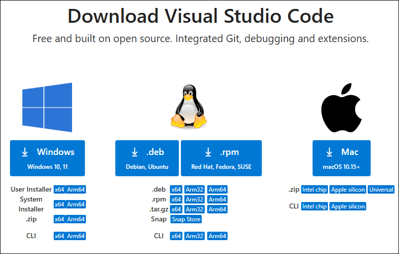
- Open the download page of VScode official website, choose the corresponding system and system bit to download

- After running the installation package, the rest can be installed by default, but here for the subsequent experience, it is recommended to check boxes 1, 2, and 3
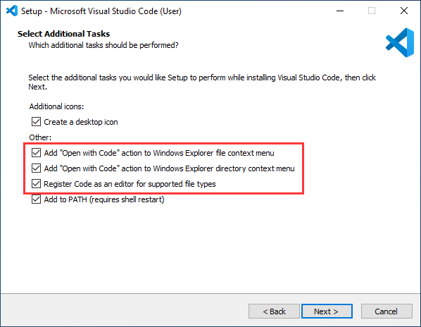
- After the first two items are enabled, you can open VSCode directly by right-clicking files or directories, which can improve the subsequent user experience.
- After the third item is enabled, you can select VSCode directly when you choose how to open it
Install Espressif IDF Plugin
- It is generally recommended to use Install Online. If online installation fails due to network factor, use Install Offline.
- For more information about how to install the Espressif IDF plugin, see Install Espressif IDF Plugin
Run the First ESP-IDF Demo
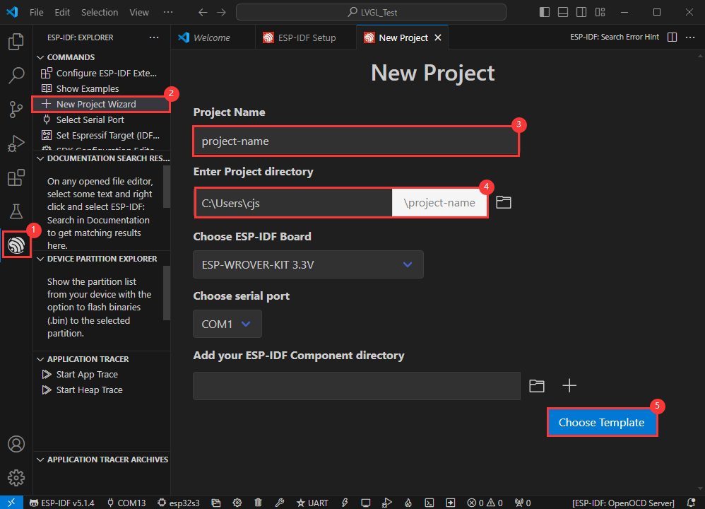
New Project
Create Demo
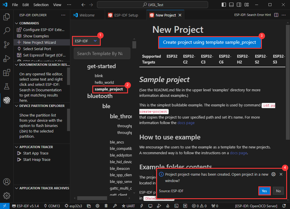
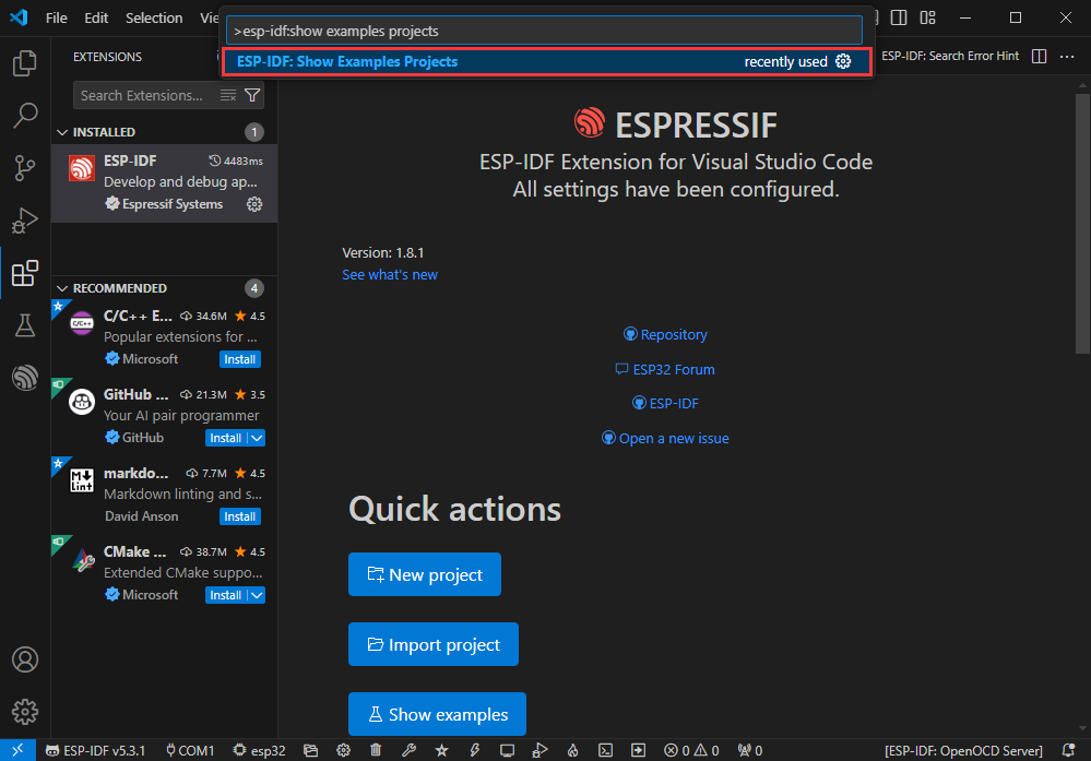
- Using the shortcut F1, enter esp-idf:show examples projects
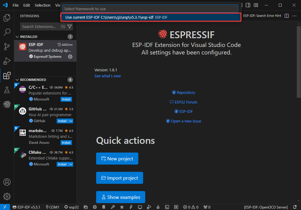
- Select your current IDF version
- Take the Hello world demo as an example
①Select the corresponding demo
②Its readme will state what chip the demo applies to (how to use the demo and the file structure are described below, omitted here)
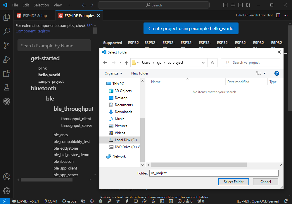
③Click to create the demo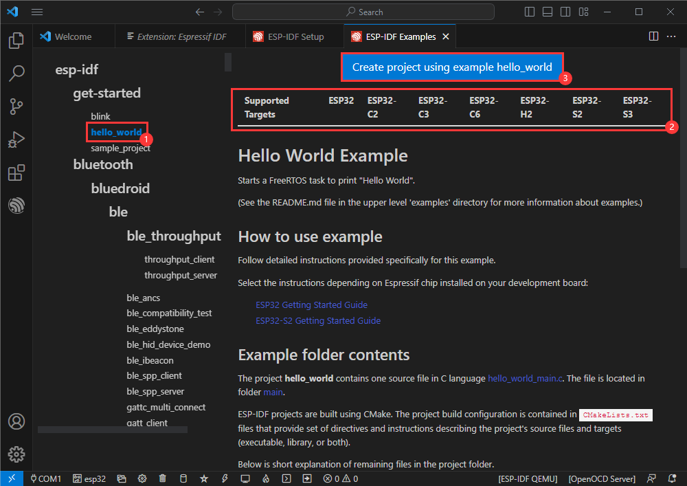
- Select the path to save the demo, and require that the demos cannot use folders with the same name
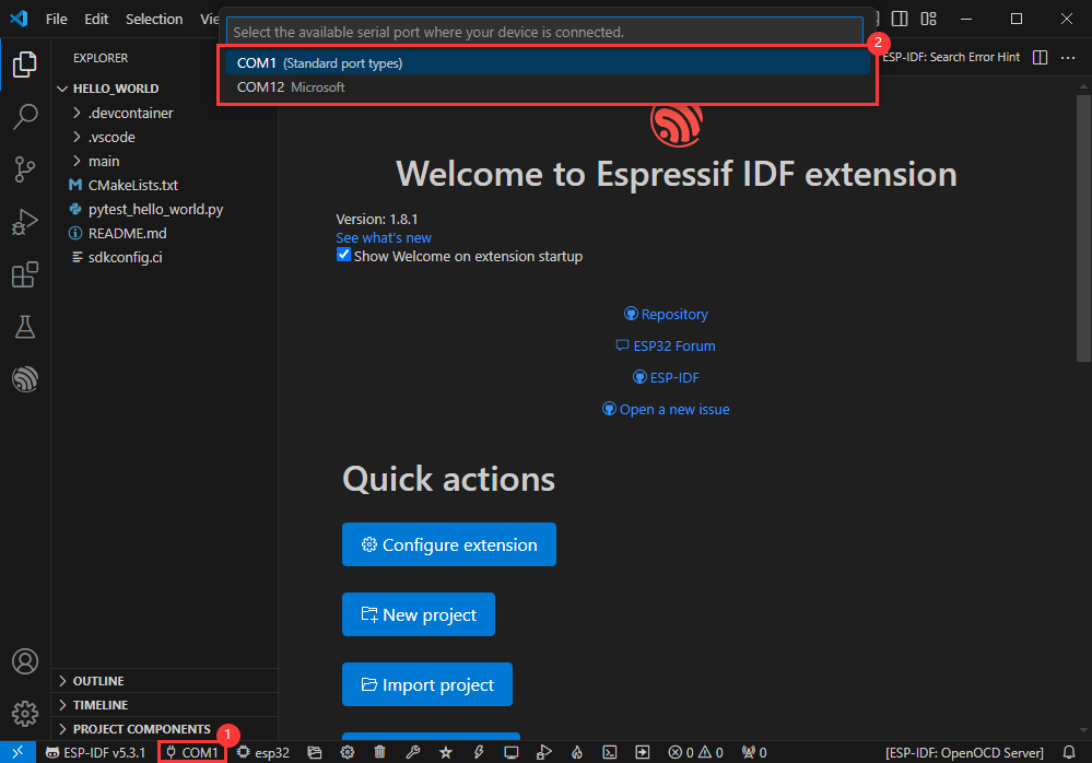
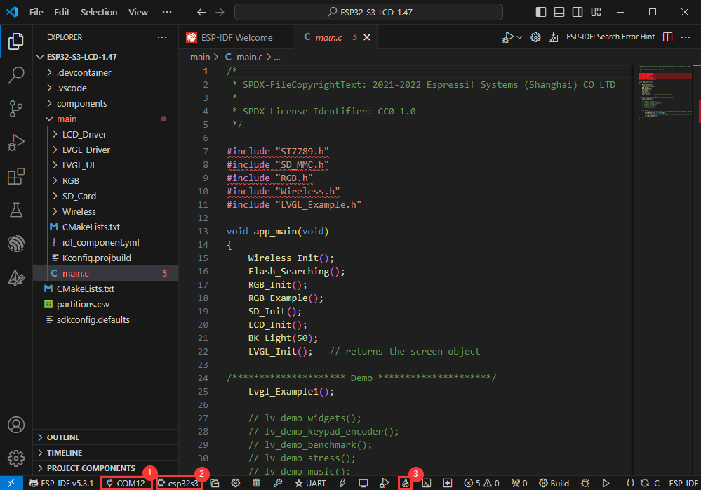
Modify COM Port
- The corresponding COM ports are shown here, click to modify them
- Please select the COM ports according to your device (You can view it from the device manager)
- In case of a download failure, please press the Reset button for more than 1 second or enter download mode, and wait for the PC to recognize the device again before downloading once more
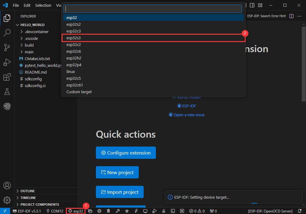
Modify Driver Object
- Select the object we need to drive, which is our main chip ESP32S3
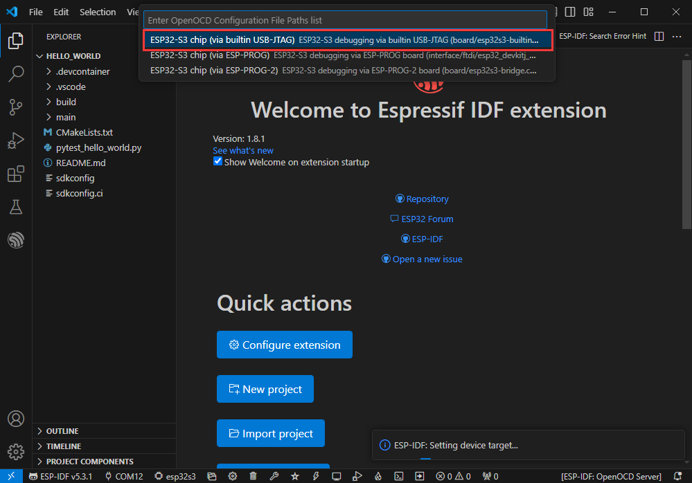
- Choose the openocd path, it doesn't affect us here, so let's just choose one
Other Status Bar Functions
①.ESP-IDF Development Environment Version Manager, when our project requires differentiation of development environment versions, it can be managed by installing different versions of ESP-IDF. When the project uses a specific version, it can be switched to by utilizing it
②.Device flashing COM port, select to flash the compiled program into the chip
③.Select set-target chip model, select the corresponding chip model, for example, ESP32-P4-NANO needs to choose esp32p4 as the target chip
④.menuconfig, click it to Modify sdkconfig configuration file Project configuration details
⑤.fullclean button, when the project compilation error or other operations pollute the compiled content, you can clean up all the compiled content by clicking it
⑥.Build project, when a project satisfies the build, click this button to compile
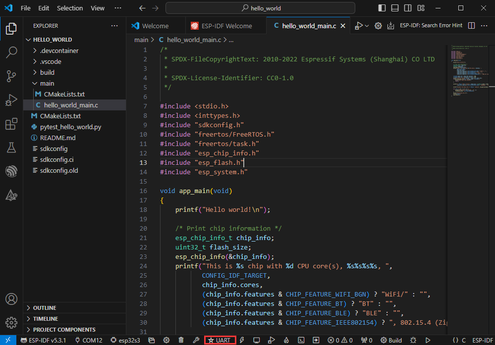
⑦.Current download mode, the default is UART
⑧.flash button, when a project build is completed, select the COM port of the corresponding development board, and click this button to flash the compiled firmware to the chip
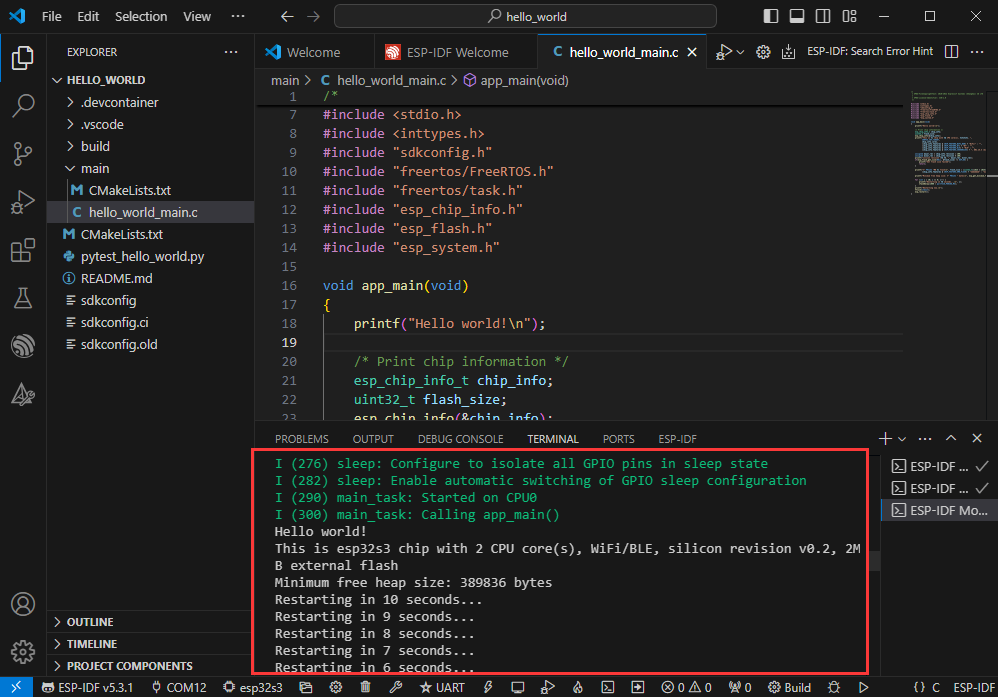
⑨.monitor enable flashing port monitoring, when a project passes through Build --> Flash, click this button to view the log of output from flashing port and debugging port, so as to observe whether the application works normally
⑩.Debug
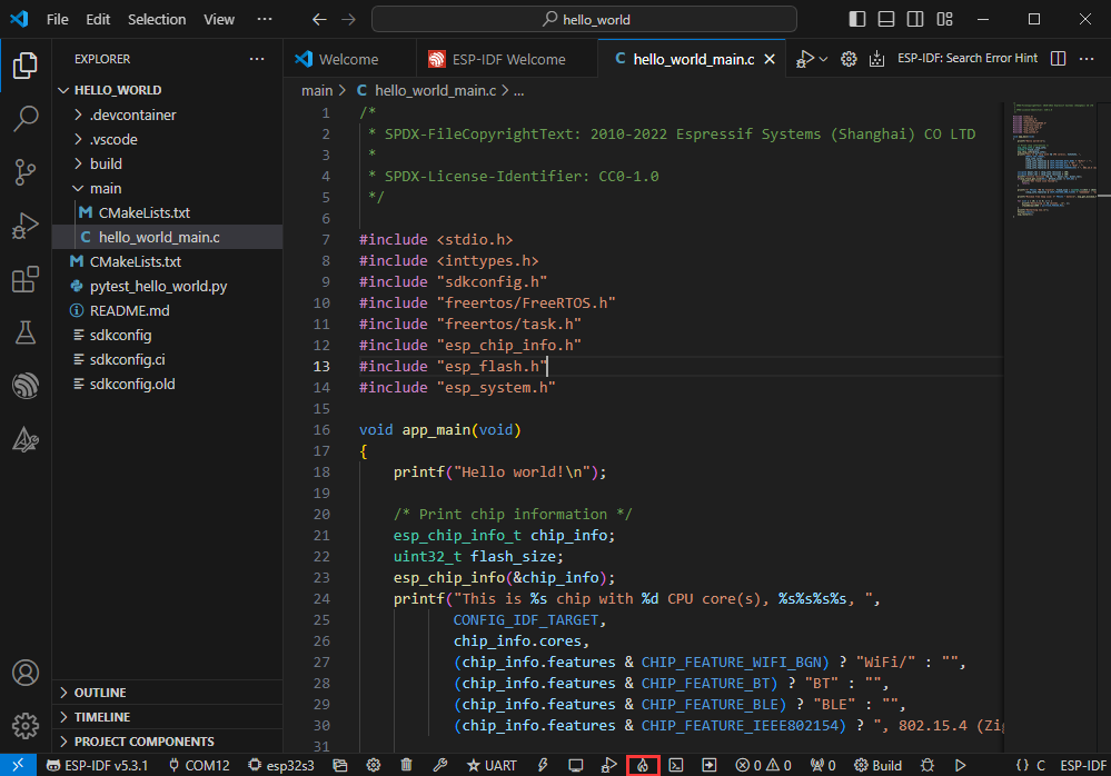
⑪.Build Flash Monitor one-click button, which is used to continuously execute Build --> Flash --> Monitor, often referred to as "little flame"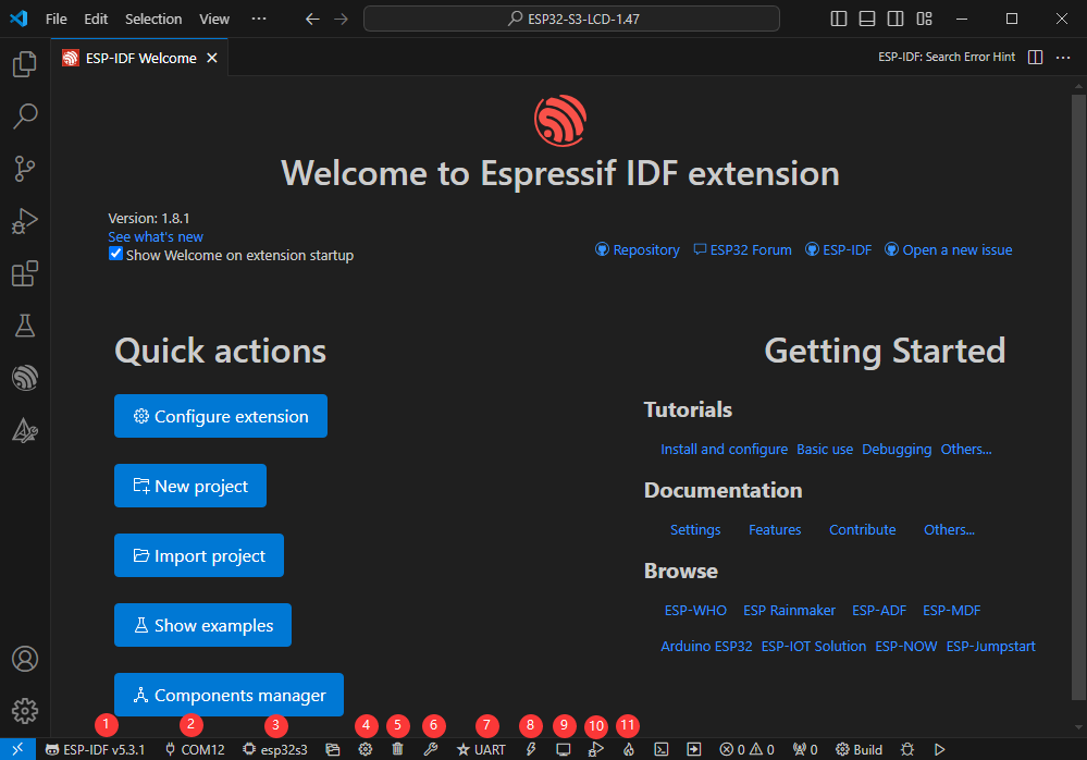
Compile, Flash and Serial Port Monitor
- Click on the all-in-one button we described before to compile, flash and open the serial port monitor
- It may take a long time to compile especially for the first time
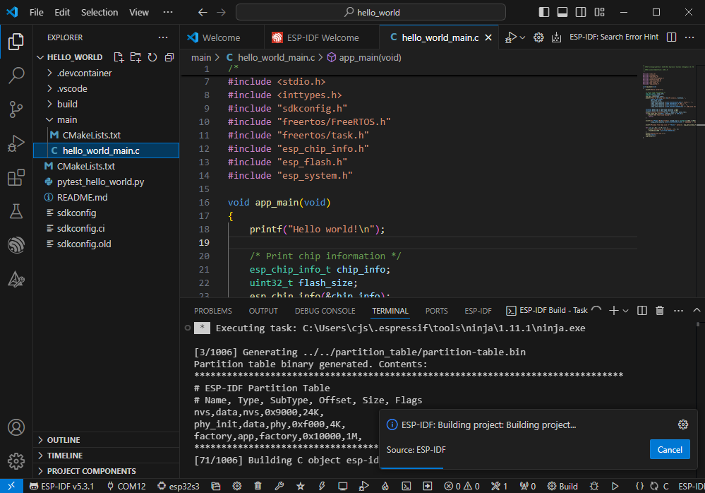
- During this process, the ESP-IDF may take up a lot of CPU resources, so it may cause the system to lag
- If it is the first time to flash the program for a new project, you will need to select the download method, and select UART
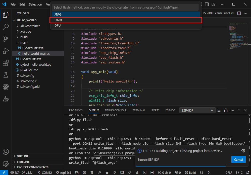
- This can also be changed later in the Download methods section (click on it to pop up the options)
- As it comes with the onboard automatic download circuit, it can be downloaded automatically without manual operation
- After successful download, it will automatically enter the serial monitor, you can see the chip output the corresponding information and be prompted to restart after 10S
Use the IDF Demos
Open In the Software
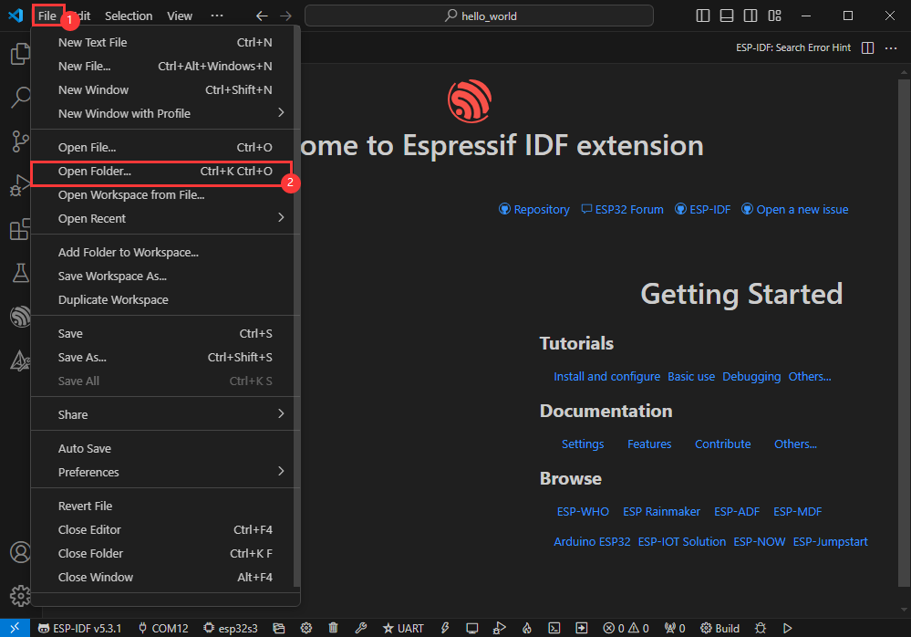
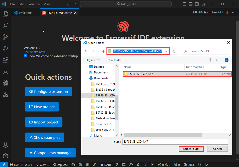
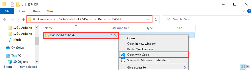
- Open VScode software and select the folder to open the demo
- Select the provided ESP-IDF example and click to select the file (located in the /Demo/ESP-IDF path under demo)
Open from Outside the Software
- Select the project directory correctly and open the project, otherwise it will affect the compilation and flashing of subsequent programs
- After connecting the device, select the COM port and model, click below to compile and flash to achieve program control
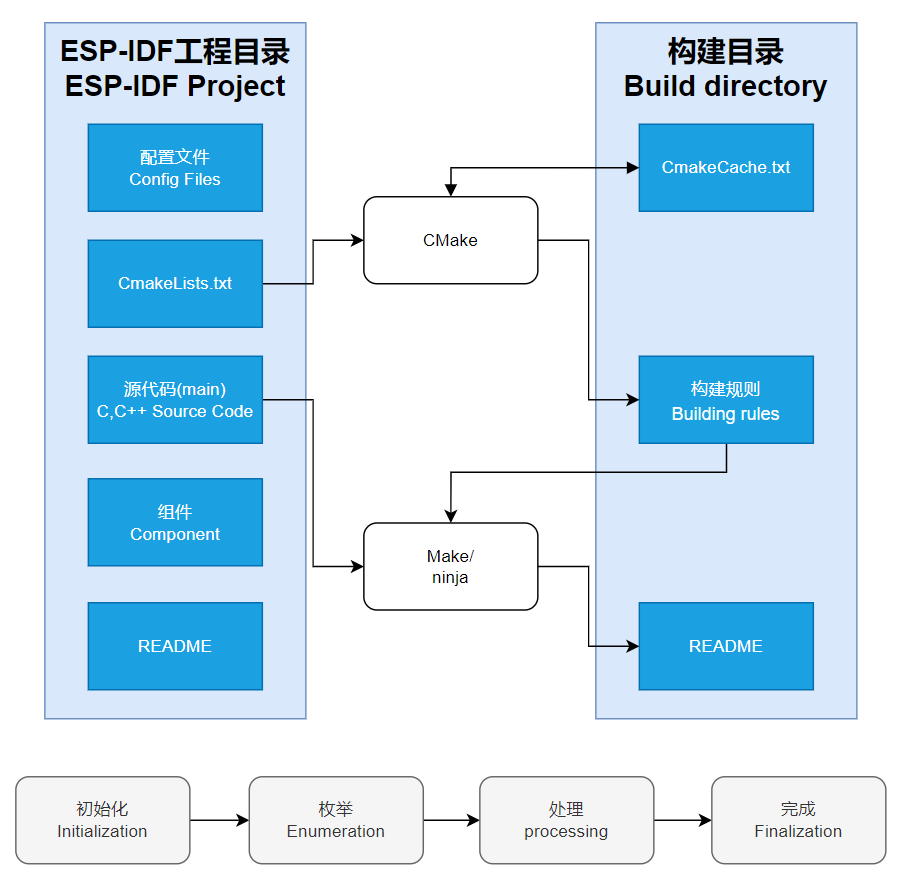
ESP-IDF Project Details
- Component: The components in ESP-IDF are the basic modules for building applications, each component is usually a relatively independent code base or library, which can implement specific functions or services, and can be reused by applications or other components, similar to the definition of libraries in Python development.
- Component reference: The import of libraries in the Python development environment only requires to "import library name or path", while ESP-IDF is based on the C language, and the importing of libraries is configured and defined through
CMakeLists.txt. - The purpose of CmakeLists.txt: When compiling ESP-IDF, the build tool
CMakefirst reads the content of the top-levelCMakeLists.txtin the project directory to read the build rules and identify the content to be compiled. When the required components and demos are imported into theCMakeLists.txt, the compilation toolCMakewill import each content that needs to be compiled according to the index. The compilation process is as follows:
- Component reference: The import of libraries in the Python development environment only requires to "import library name or path", while ESP-IDF is based on the C language, and the importing of libraries is configured and defined through
Demo
| Demo | Basic Description |
|---|---|
| 01_GPIO | Test GPIO |
| 02_UART | Test UART |
| 03_I2C | Test I2C |
| 04_CAN | Test CAN |
| 05_RS485 | Test I2C |
| 06_LCD | Test display |
| 07_SD | Test TF card |
| 08_TOUCH | Test touchscreen |
| 09_DISPLAY_BMP | Display BMP images from the TF card on the screen |
| 11_WIFI_STA | Connect to the AP and display the IP |
| 12_WIFI_AP | Start AP and display the MAC address of connected devices |
| 13_LVGL_TRANSPLANT | Transplant LVGL |
| 14_LVGL_BTN | Draw a button to control GPIO operation |
| 15_LVGL_SLIDER | Draw a slider to control backlight and GPIO output, and simultaneously display battery voltage |
| 16_LVGL_UI | Comprehensive demo |
- Demos 08, 09, 13, 14, 15 and 16 can only be applied to boards with touch screens.
01_GPIO
Hardware connection
- Connect the board to the computer using a USB cable
- Connect the LED module to the GPIO

Code analysis
app_main():- Firstly, initialize GPIO 6 and set it to output mode.
- Firstly, initialize GPIO 6 and set it to output mode.
- Finally, the core function of the loop section is to pull the GPIO pin high or low to control the LED to turn on and off.
- Finally, the core function of the loop section is to pull the GPIO pin high or low to control the LED to turn on and off.
Result demonstration
- After successful flashing, the screen shows nothing, and the connected LED lights will turn on and off at a frequency of 1 Hz
02_UART
Hardware connection
- Connect the UART port of the board to the computer using a USB cable
Code analysis
app_main():- First of all, it is mainly used to initialize serial communication and allocate a temporary buffer for receiving data
- First of all, it is mainly used to initialize serial communication and allocate a temporary buffer for receiving data
- Finally, the loop implements a simple UART communication data backhaul
- Finally, the loop implements a simple UART communication data backhaul
By checking whether there is data available on the serial port, if there is data, it is read and immediately sent back, achieving the function of returning the received UART data intact.
Result demonstration
- After successful flashing, open the serial port debugging assistant to send a message to the ESP32-S3-Touch-LCD-7B, and the device will return the received message to the serial port debugging assistant

03_I2C
Hardware connection
- Connect the UART port of the board to the computer using a USB cable
Code analysis
app_main():- Firstly, initialize I2C and IO extensions.
- Firstly, initialize I2C and IO extensions.
DEV_I2C_Init():
DEV_I2C_Init() function initializes the I2C device
IO_EXTENSION_Init():
IO_EXTENSION_Init() function initializes IO extension.
- Finally, the loop control IO expansion chip to repeatedly pull the DISP pin high or low, thereby controlling the screen backlight on and off.
- Finally, the loop control IO expansion chip to repeatedly pull the DISP pin high or low, thereby controlling the screen backlight on and off.
IO_EXTENSION_Output(uint8_t pin, uint8_t value):
IO_EXTENSION_Output(uint8_t pin, uint8_t value) function controls the IO expansion chip to output a specified level.
Result demonstration
- After successful flashing, the screen backlight will turn on and off at a frequency of 1Hz
04_CAN
Hardware connection
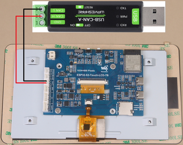
- Connect the board to the computer using a USB cable
- Connect the development board to USB-CAN-A, as shown in the figure
Code analysis
app_main():- First initialize the I2C, IO expansion, and CAN interface. Before initializing the CAN interface, it needs to control IO_EXTENSION_IO_5 to a high level; otherwise, the CAN interface will not work.
- First initialize the I2C, IO expansion, and CAN interface. Before initializing the CAN interface, it needs to control IO_EXTENSION_IO_5 to a high level; otherwise, the CAN interface will not work.
can_init(twai_timing_config_t t_config, twai_filter_config_t f_config, twai_general_config_t g_config):can_initfunction is mainly responsible for handling the initialization of TWAI (an interface similar to the CAN bus)
- Finally, loop through to check if any alarms have occurred. Read the triggered alerts by calling
can_read_alertsand obtain the TWAI status information intoalerts_triggered. Then, according to the different alarms triggered, perform corresponding processing. For example, if an error passive alarm, a bus error alarm, a transmission failure alarm, or a transmission success alarm is triggered, print the corresponding message and output some status information such as the bus error count, the number of messages to be sent, the transmission error counter, and the transmission failure counter. - If the correct data is read, it will read the information and then send the data back unchanged.
- Finally, loop through to check if any alarms have occurred. Read the triggered alerts by calling
Result demonstration
- After successful flashing, the screen will not display
- After configuring USB-CAN-A_TOOL, start and send a CAN message to ESP32-S3-Touch-LCD-7B. You can see that ESP32-S3-Touch-LCD-7B returns the same message.

05_RS485
Hardware connection
- Connect the board to the computer using a USB cable
- Connect the development board to USB to RS485 converter, as shown in the figure
Code analysis
app_main():- First initialize serial communication
- First initialize serial communication
Initialize the serial port using the DEV_UART_Init function, set the baud rate, configure the receive and transmit pins, and allocate a temporary buffer for receiving data.
- Finally, the loop implements a simple RS485 communication data backhaul
- Finally, the loop implements a simple RS485 communication data backhaul
By checking whether there is data available on the serial port, if there is data, it is read and immediately sent back, achieving the function of returning the received RS485 data intact.
Result demonstration
- After successful flashing, open the serial port debugging assistant to send a message to the ESP32-S3-Touch-LCD-7B, and the device will return the received message to the serial port debugging assistant

06_LCD
Hardware connection
- Connect the board to the computer using a USB cable
Code analysis
app_main():- Mainly perform a series of initialization operations and tests on the display
- First, it initializes I2C, IO expansion, and the RGB LCD, and then turns on the backlight. Then create a buffer to store the image, initialize the GUI image data, set the current image format and rotation angle, and finally start controlling the screen to display the corresponding interface.
- During the test, you can set the rotation angle yourself (in line 18) to realize the display of different angles.
waveshare_esp32_s3_rgb_lcd_init():waveshare_esp32_s3_rgb_lcd_initfunction mainly initializes the RGB LCD.
wavesahre_rgb_lcd_bl_on():wavesahre_rgb_lcd_bl_onfunction mainly turns on the LCD backlight.- For more functions, they are also explained in the example, which can be viewed directly in the example.
Result demonstration
- After successful flashing, ESP32-S3-Touch-LCD-7B will first display the RGB565 color box, then show the pattern and text, and finally display the image.
07_SD
Hardware connection
- Connect the board to the computer using a USB cable
- Connect the TF card to ESP32-S3-Touch-LCD-7B
Code analysis
app_main():- Mainly performs a series of initialization operations and tests on the TF card, and displays relevant information on the screen.
sd_mmc_init():
sd_mmc_init function mainly initializes and mounts the TF card.
read_sd_capacity(uint64_t *total_capacity, uint64_t *available_capacity):
read_sd_capacity function primarily reads the memory information of the TF card.
Result demonstration
- After successful flashing, ESP32-S3-Touch-LCD-7B will display TF card information, if not, it will display "SD Card Fail!"
08_TOUCH
Hardware connection
- Connect the board to the computer using a USB cable
Code analysis
app_main():- Mainly performs a series of initialization operations and tests on the touch screen, and displays relevant information on the screen.
touch_gt911_init():
touch_gt911_init function mainly initializes the touchscreen.
touch_gt911_read_point(uint8_t max_touch_cnt) : touch_gt911_read_point function mainly reads the current coordinate point and can recognize up to 5 touch points.
Result demonstration
- After successful flashing, points will be displayed on the screen when touching the screen, and touching five points at the same time will display five different colored points.
09_DISPLAY_BMP
Hardware connection
- Connect the board to the computer using a USB cable
- Save the images in the directory to the TF card and connect it to ESP32-S3-Touch-LCD-7B
Code analysis
app_main():- Mainly performs a series of initialization operations and reads image files, and switches display by clicking the arrow on the screen.
list_files(const char *base_path):
list_files function mainly reads BMP image file names and saves the names to BmpPath.
GUI_ReadBmp(UWORD Xstart, UWORD Ystart, const char *path):
GUI_ReadBmp function primarily reads BMP image data from the TF card and writes the data into the buffer, with the position determined by Xstart and Ystart.
Result demonstration
- After successful flashing, if the mounting is successful, an arrow will be displayed. Click the arrow to show the image, and clicking it again will switch the image left or right.
10_WIFI_SCAN
Hardware connection
- Connect the board to the computer using a USB cable
Code analysis
app_main():- Mainly performs a series of initialization operations and scans nearby Wi-Fi, and displays the names of the scanned Wi-Fi networks on the screen (currently, it cannot display Chinese characters because the font library is not comprehensive enough).
wifi_scan():
wifi_scan function primarily scans for nearby Wi-Fi and writes the data to a cache buffer.
Result demonstration
- After successful flashing, start scanning, the current WiFi name will be displayed after scanning ends.
11_WIFI_STA
Hardware connection
- Connect the board to the computer using a USB cable
Code analysis
app_main():- Mainly performs a series of initialization operations and connects to the specified WIFI (2.4GHz), and displays the IP address of the WIFI on the screen.
Result demonstration
- After successful flashing, connect to the set WIFI, and after the connection is successful, print the IP address on the screen
12_WIFI_AP
Hardware connection
- Connect the board to the computer using a USB cable
Code analysis
app_main():- Mainly performs a series of initialization operations and creates a hotspot named ESP32-S3-Touch-LCD-7B, and displays the MAC address of the currently connected device on the screen.
Result demonstration
- After successful flashing, start the hotspot and display the MAC address of the connected device
13_LVGL_TRANSPLANT
Hardware connection
- Connect the board to the computer using a USB cable
Code analysis
app_main():- Mainly performs a series of initialization operations and runs the LVGL Demo.
Result demonstration
- After successful flashing, it will run lv_demo_widgets, allowing for interactive operations.
Other instructions
- Screen drifting occurs during use, please refer to ESP official FAQ
- When using your own UI program, there is a lack of memory, you can click Tools to select a larger partition table

- The version of lvgl used is 8.4, and you can query and use the LVGL API through the following documentation
14_LVGL_BTN
Hardware connection
- Connect the board to the computer using a USB cable
- Connect the LED module to the GPIO

Code analysis
app_main():- Mainly performs a series of initialization operations and creates a button. Clicking the button can control the LED to turn on or off.
Result demonstration
- After successful flashing, a button will be displayed. Click the button to change the state of the GPIO to control the LED on and off
15_LVGL_SLIDER
Hardware connection
- Connect the board to the computer using a USB cable
- Connect the LED module to the GPIO

Code analysis
app_main():- Mainly performs a series of initialization operations and creates a slider and text (displaying battery voltage).
Result demonstration
- After successful flashing, a slider showing the current battery voltage will be displayed. By controlling the slider, you can simultaneously adjust the brightness of the LED and the screen.
16_LVGL_UI
Hardware connection
- Connect the board to the computer using a USB cable
Code analysis
app_main():- Mainly performs a series of initialization operations and creates a custom GUI interface. The GUI is designed by SquareLine Studio, since it is only used to draw graphics, it does not provide SquareLine Studio projects.
Result demonstration
- After the flashing is successful, you can perform the following steps:
- The first time you run it, you need to create a login and password
- After the creation is completed, click the button to return to the login interface, and enter the username and password to log in
- After logging in, you can see four boxes, corresponding to different functions
WIFI: It can test Scan, STA, and AP, and display related WiFi informationRS485: It can test the RS485 function, set the baud rate, send and receive dataCAN: It can test CAN functions, set the rate, and send and receive dataPWM: It can test backlight, battery voltage reading, and TF card
PlatformIO Development
This chapter introduces setting up the platformio environment, including the program compilation and downloading, as well as testing demos. It aims to help users master the development board and facilitate secondary development
Environment Setup
Download and Install Visual Studio
- Open the download page of VScode official website, choose the corresponding system and system bit to download
- After running the installation package, the rest can be installed by default, but here for the subsequent experience, it is recommended to check boxes 1, 2, and 3

- After the first two items are enabled, you can open VSCode directly by right-clicking files or directories, which can improve the subsequent user experience.
- After the third item is enabled, you can select VSCode directly when you choose how to open it
Install PlatformIO IDE Plugin
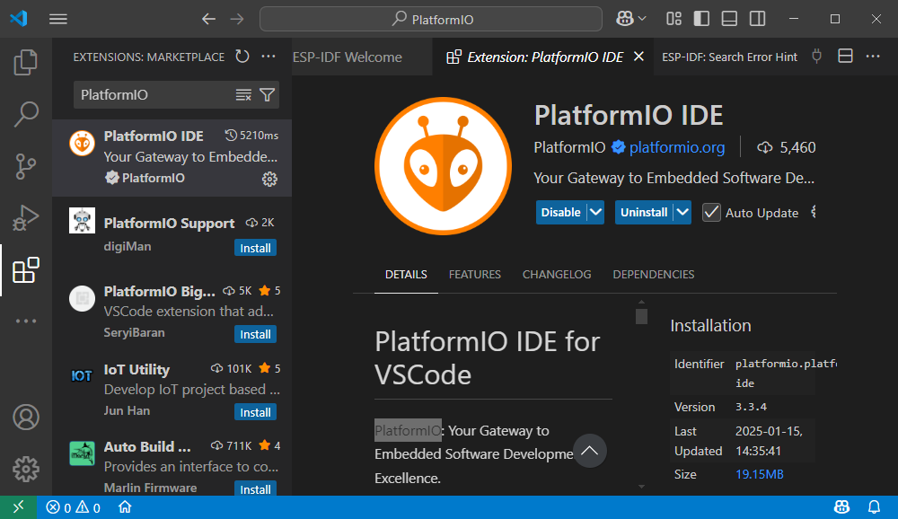
- Open VSCode, click on Extensions on the left, search for and install PlatformIO IDE in the extensions.
Run the First PlatformIO Demo
New Project
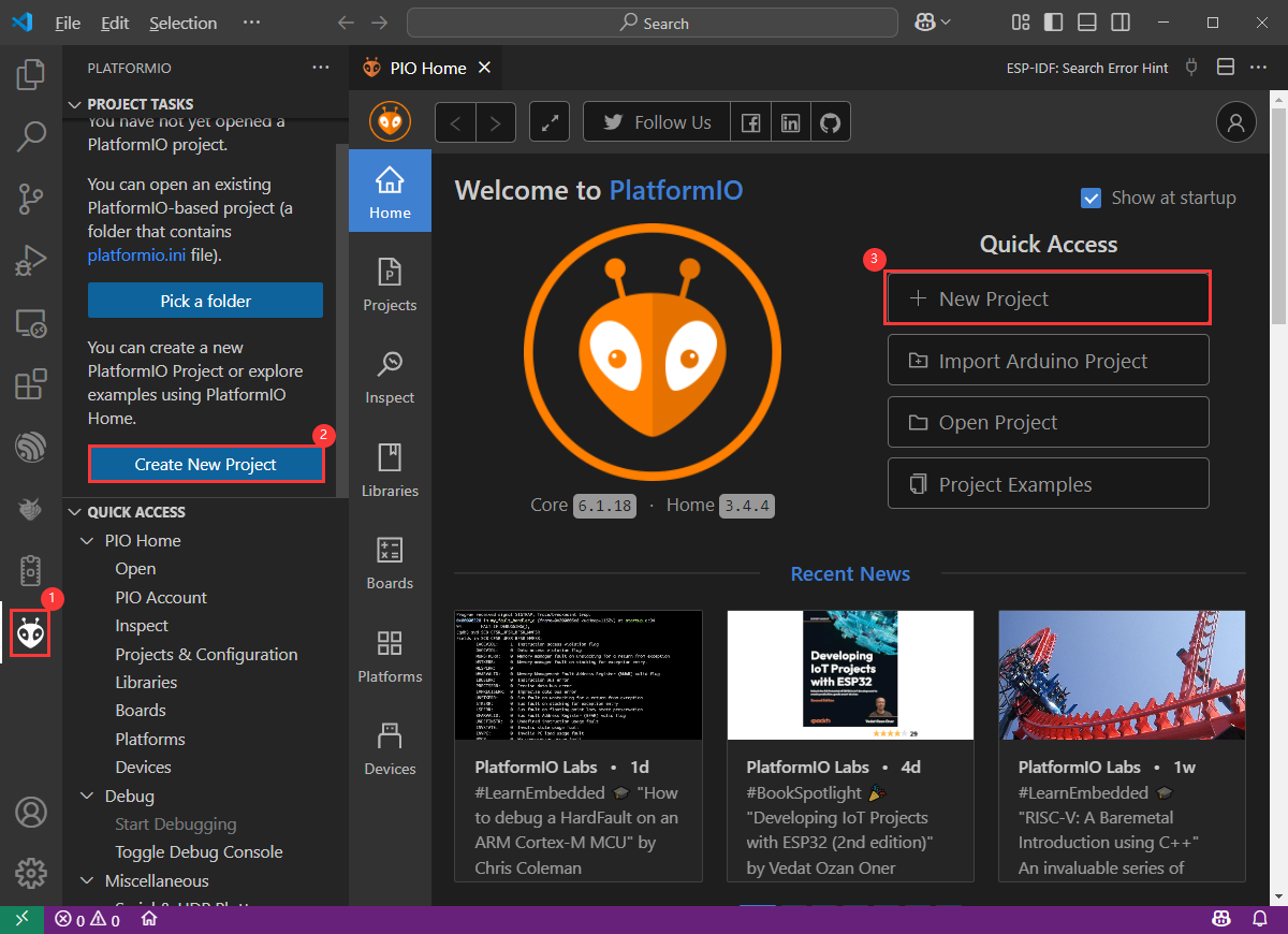
- Open VS Code, if the PlatformIO IDE plugin is already installed, click on the PlatformIO icon, select
Create New Project->New Projject-> Set the project name and board model, such as Hello_World
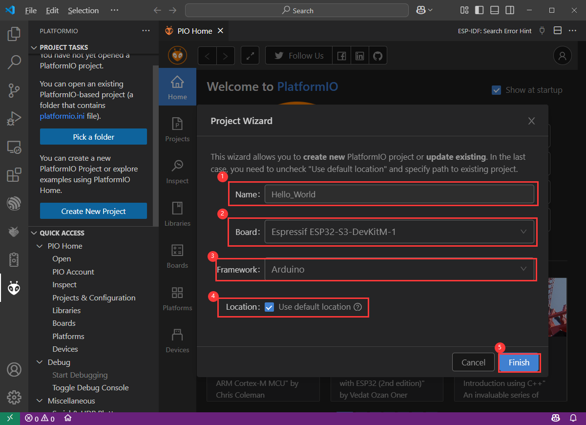
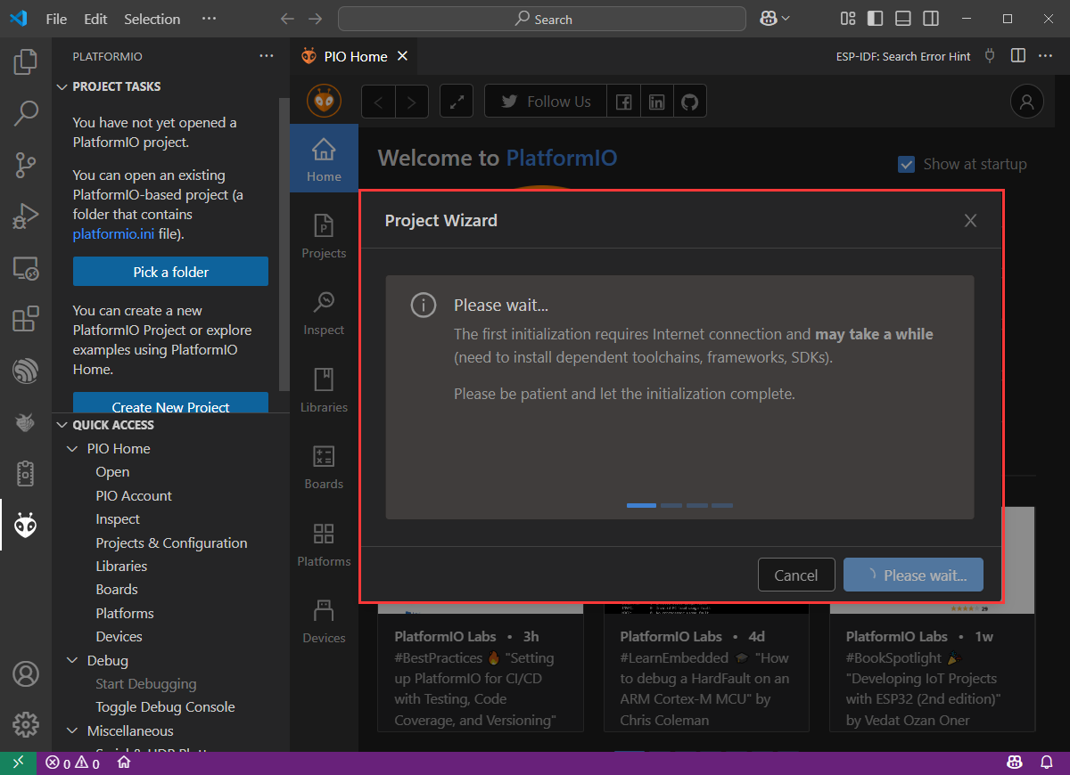
- The first run requires waiting for PlatformIO to download the relevant packages, which may take a long time, so please be patient
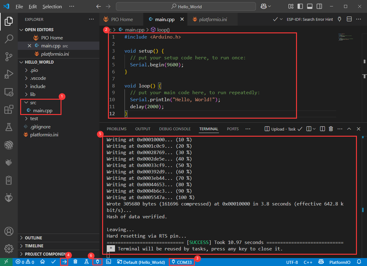
- Enter the code:
void setup() {
  // put your setup code here, to run once:
  Serial.begin(9600);
}

void loop() {
  // put your main code here, to run repeatedly:
  Serial.println("Hello, World!");
  delay(2000);
}- Save the code file, connect the development board to the computer, choose
Port->Compile and Flash; When the fifth item is displayed, it indicates that the flashing is successful. Then click on the sixth item to observe the operation of the demo

Compile and Flash Demos
- Compile and flash according to the following steps:
①. Click to open main.cpp file;
②. Enter the code given above and save it;
③. Select COM Port;
④. Compile and flash the demo.
⑤. If SUCCESS appears, it indicates successful flashing.
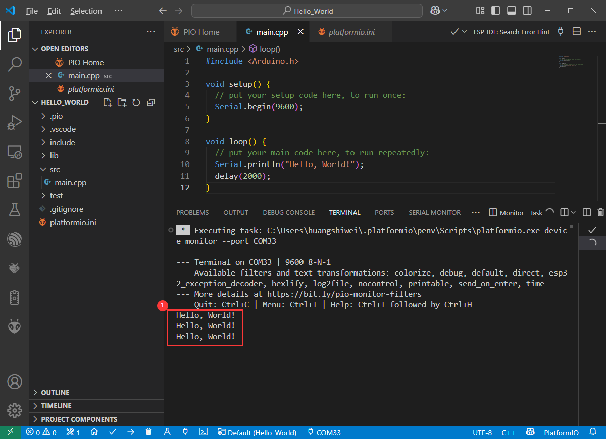
⑥. Click on serial port assistant, and repeatedly output Hello, World!, then it is successful.
Demo
| Demo | Basic Description | Dependency Library |
|---|---|---|
| 01_GPIO | Test GPIO | - |
| 02_UART | Test UART | - |
| 03_I2C | Test I2C | - |
| 04_CAN | Test CAN | - |
| 05_RS485 | Test I2C | - |
| 06_LCD | Test display | - |
| 07_SD | Test TF card | - |
| 08_TOUCH | Test touchscreen | - |
| 09_DISPLAY_BMP | Display BMP images from the TF card on the screen | - |
| 11_WIFI_STA | Connect to the AP and display the IP | - |
| 12_WIFI_AP | Start AP and display the MAC address of connected devices | - |
| 13_LVGL_TRANSPLANT | Transplant LVGL | LVGL |
| 14_LVGL_BTN | Draw a button to control GPIO operation | LVGL |
| 15_LVGL_SLIDER | Draw a slider to control backlight and GPIO output, and simultaneously display battery voltage | LVGL |
- Demos 08, 09, 13, 14, and 15 can only be applied to boards with touch screens.
01_GPIO
Hardware connection
- Connect the board to the computer using a USB cable
- Connect the LED module to the GPIO

Code analysis
setup():
setup() function initializes GPIO 6 and sets it to output mode.
loop():
loop() function is the main loop of the program, with the core functionality of repeatedly pulling the GPIO pin high or low to control the LED's on and off.
Result demonstration
- After successful flashing, the screen shows nothing, and the connected LED lights will turn on and off at a frequency of 1 Hz
02_UART
Hardware connection
- Connect the UART port of the board to the computer using a USB cable
Code analysis
setup():
setup function is primarily used for initializing serial communication
Use the UART.begin function to initialize serial port Serial , set the baud rate, data format, and specify the receive and transmit pins. Then, through a loop, ensure the serial port initialization is successful.
loop():
loop function is the main loop part of the program, and its main function is to implement simple UART communication data return
By checking whether there is data available at the serial port, if there is data, it reads a byte and sends it back immediately, so that the received UART data can be sent back intact
Result demonstration
- After successful flashing, open the serial port debugging assistant to send a message to the ESP32-S3-Touch-LCD-7B, and the device will return the received message to the serial port debugging assistant
03_I2C
Hardware connection
- Connect the UART port of the board to the computer using a USB cable
Code analysis
setup():
setup() function initializes I2C and IO expansion.
DEV_I2C_Init():
DEV_I2C_Init() function initializes the I2C device
IO_EXTENSION_Init():
IO_EXTENSION_Init() function initializes IO extension.
loop():
loop() function is the main loop of the program, with the core functionality of controlling the IO expansion chip to repeatedly pull the DISP pin high or low, thereby controlling the screen backlight on and off.
IO_EXTENSION_Output(uint8_t pin, uint8_t value):
IO_EXTENSION_Output(uint8_t pin, uint8_t value) function controls the IO expansion chip to output a specified level.
Result demonstration
- After successful flashing, the screen backlight will turn on and off at a frequency of 1Hz
04_CAN
Hardware connection
- Connect the board to the computer using a USB cable
- Connect the development board to USB-CAN-A, as shown in the figure

Code analysis
setup():
setup() function initializes I2C, IO expansion, and CAN interface. Before initializing the CAN interface, it needs to control IO_EXTENSION_IO_5 to a high level; otherwise, the CAN interface will not work.
can_init(twai_timing_config_t t_config, twai_filter_config_t f_config, twai_general_config_t g_config):can_initfunction is mainly responsible for handling the initialization of TWAI (an interface similar to the CAN bus)
loop():
loop() function checks if any alarms occur. Read the triggered alerts by calling can_read_alerts and obtain the TWAI status information into alerts_triggered . Then, according to the different alarms triggered, perform corresponding processing. For example, if an error passive alarm, a bus error alarm, a transmission failure alarm, or a transmission success alarm is triggered, print the corresponding message and output some status information such as the bus error count, the number of messages to be sent, the transmission error counter, and the transmission failure counter.
- If the correct data is read, it will read the information and then send the data back unchanged.
Result demonstration
- After successful flashing, the screen will not display
- After configuring USB-CAN-A_TOOL, start and send a CAN message to ESP32-S3-Touch-LCD-7B. You can see that ESP32-S3-Touch-LCD-7B returns the same message.


05_RS485
Hardware connection
- Connect the board to the computer using a USB cable
- Connect the development board to USB to RS485 converter, as shown in the figure
Code analysis
setup():
setup function is primarily used for initializing serial communication
Use the RS485.begin function to initialize serial port Serial1, set the baud rate, data format, and specify the receive and transmit pins. Then, through a loop, ensure the serial port initialization is successful.
loop():
loop function is the main loop part of the program, and its main function is to implement simple 485 communication data return
By checking whether there is data available at the serial port, if there is data, it reads a byte and sends it back immediately, so that the received 485 data can be sent back intact
Result demonstration
- After successful flashing, open the serial port debugging assistant to send a message to the ESP32-S3-Touch-LCD-7B device (the message must contain a newline, otherwise no data will be returned), and the device will return the received message to the serial port debugging assistant

06_LCD
Hardware connection
- Connect the board to the computer using a USB cable
Code analysis
setup():setupfunction mainly performs a series of initialization operations and tests on the display- First, it initializes I2C, IO expansion, and the RGB LCD, and then turns on the backlight. Then create a buffer to store the image, initialize the GUI image data, set the current image format and rotation angle, and finally start controlling the screen to display the corresponding interface.
- During the test, you can set the rotation angle yourself (in line 13) to realize the display of different angles.
- First, it initializes I2C, IO expansion, and the RGB LCD, and then turns on the backlight. Then create a buffer to store the image, initialize the GUI image data, set the current image format and rotation angle, and finally start controlling the screen to display the corresponding interface.
waveshare_esp32_s3_rgb_lcd_init():waveshare_esp32_s3_rgb_lcd_initfunction mainly initializes the RGB LCD.
wavesahre_rgb_lcd_bl_on():wavesahre_rgb_lcd_bl_onfunction mainly turns on the LCD backlight.- For more functions, they are also explained in the example, which can be viewed directly in the example.
Result demonstration
- After successful flashing, ESP32-S3-Touch-LCD-7B will first display the RGB565 color box, then show the pattern and text, and finally display the image.
07_SD
Hardware connection
- Connect the board to the computer using a USB cable
- Connect the TF card to ESP32-S3-Touch-LCD-7B
Code analysis
setup():
setup function mainly performs a series of initialization operations and tests on the TF card, and displays relevant information on the screen.
sd_mmc_init():
sd_mmc_init function mainly initializes and mounts the TF card.
read_sd_capacity(uint64_t *total_capacity, uint64_t *available_capacity):
read_sd_capacity function primarily reads the memory information of the TF card.
Result demonstration
- After successful flashing, the running effect: ESP32-S3-Touch-LCD-7B will display TF card information, if not, it will display "SD Card Fail!"
08_TOUCH
Hardware connection
- Connect the board to the computer using a USB cable
Code analysis
setup():
setup function mainly performs a series of initialization operations and tests on the touch screen, and displays it on the screen.
touch_gt911_init():
touch_gt911_init function mainly initializes the touchscreen.
touch_gt911_read_point(uint8_t max_touch_cnt) : touch_gt911_read_point function mainly reads the current coordinate point and can recognize up to 5 touch points.
Result demonstration
- After successful flashing, points will be displayed on the screen when touching the screen, and touching five points at the same time will display five different colored points.
09_DISPLAY_BMP
Hardware connection
- Connect the board to the computer using a USB cable
- Save the images in the directory to the TF card and connect it to ESP32-S3-Touch-LCD-7B
Code analysis
setup():
setup function mainly performs a series of initialization operations and reads image files, and switches display by clicking the arrow on the screen.
list_files(const char *base_path):
list_files function mainly reads BMP image file names and saves the names to BmpPath.
GUI_ReadBmp(UWORD Xstart, UWORD Ystart, const char *path):
GUI_ReadBmp function primarily reads BMP image data from the TF card and writes the data into the buffer, with the position determined by Xstart and Ystart.
Result demonstration
- After successful flashing, if the mounting is successful, an arrow will be displayed. Click the arrow to show the image, and clicking it again will switch the image left or right.
10_WIFI_SCAN
Hardware connection
- Connect the board to the computer using a USB cable
Code analysis
setup():
setup function mainly performs a series of initialization operations and scans nearby Wi-Fi, and displays the names of the scanned Wi-Fi networks on the screen (currently, it cannot display Chinese characters because the font library is not comprehensive enough).
wifi_scan():
wifi_scan function primarily scans for nearby Wi-Fi and writes the data to a cache buffer.
Result demonstration
- After successful flashing, start scanning, the current WiFi name will be displayed after scanning ends.
11_WIFI_STA
Hardware connection
- Connect the board to the computer using a USB cable
Code analysis
setup():
setup function mainly performs a series of initialization operations and connects to the specified WIFI (2.4GHz), and displays the IP address of the WIFI on the screen.
Result demonstration
- After successful flashing, connect to the set WIFI, and after the connection is successful, print the IP address on the screen
12_WIFI_AP
Hardware connection
- Connect the board to the computer using a USB cable
Code analysis
setup():
setup function mainly performs a series of initialization operations and creates a hotspot named ESP32-S3-Touch-LCD-7B, and displays the MAC address of the currently connected device on the screen.
Result demonstration
- After successful flashing, start the hotspot and display the MAC address of the connected device
13_LVGL_TRANSPLANT
Hardware connection
- Connect the board to the computer using a USB cable
Code analysis
setup():
code> setup function mainly performs a series of initialization operations and runs the LVGL Demo.
Result demonstration
- After successful flashing, it will run lv_demo_widgets, allowing for interactive operations.
Other instructions
- Screen drifting occurs during use, please refer to ESP official FAQ
- When using your own UI program, there is a lack of memory, you can click Tools to select a larger partition table

- The version of lvgl used is 8.4, and you can query and use the LVGL API through the following documentation
14_LVGL_BTN
Hardware connection
- Connect the board to the computer using a USB cable
- Connect the LED module to the GPIO
Code analysis
setup():
setup function mainly performs a series of initialization operations and creates a button. Clicking the button can control the LED to turn on or off.
Result demonstration
- After successful flashing, a button will be displayed. Click the button to change the state of the GPIO to control the LED on and off
15_LVGL_SLIDER
Hardware connection
- Connect the board to the computer using a USB cable
- Connect the LED module to the GPIO

Code analysis
setup():
setup function mainly performs a series of initialization operations and creates a slider and text (displaying battery voltage).
Result demonstration
- After successful flashing, a slider showing the current battery voltage will be displayed. By controlling the slider, you can simultaneously adjust the brightness of the LED and the screen.
Resources
Schematic Diagram
Demo
Datasheets
ESP32-S3
Other Components
Software Tools
Arduino
VScode
Debugging Tools
Other Resource Links
- ESP32-Arduino official documentation
- ESP32-Arduino official resources
- ESP-IDF official resources
- LVGL official documentation
FAQ
Question: ESP32-S3-Touch-LCD-7B shows no response after uploading an Arduino demo for RGB screen displaying?
If there's no screen response after programming the code, check whether the correct configurations are set in Arduino IDE -> Tools, select the corresponding Flash (16MB) and enable PSRAM (8MB OPI))
Question: Why are all libraries installed, and the flashing LVGL program reports an error missing lv_cong.h?
The path to install the library contains Chinese characters, resulting in the inability to find the library file
Question: Why does error "fatal error:esp_ memory_ utils.h:No such file or directory" occur when compiling demos using the Arduino IDE?
Please install the Arduino ESP32 that we provided to solve this issue
Question:Can CAN communication use debugging tools to send continuous frames?
Yes, you can also customize the frequency of consecutive frames. When the frequency is too high and the computer freezes, it may cause bus errors
Question: What should I do if ESP-IDF flashing fails?
- You can set the board to download mode to solve this issue. Power off completely, press and hold the Boot button and power it on again, then release it, enter the download mode, re-flash the program, reset and run.
- Please try to press the fullclean button in the status bar and recompile the flashing, this function is to clean up all the compiled content by clicking when the project compilation error or other operations pollute the compiled content
Question: What should I do if I can't find the AppData folder?
Some AppData folders are hidden by default and can be set to show
- English system: Explorer->View->Check "Hidden items"
- Chinese system: File Explorer -> View -> Display -> Check "Hidden Items"
Question: How to check the COM port?
Press the Windows + R keys to open the "Run" dialog box, input devmgmt.msc and press Enter to open the Device Manager; Expand the "Port (COM and LPT)" section, here it will list all the COM ports and their current status.
Question: How to deal with the first compilation of the program being extremely slow?
It's normal for the first compilation to be slow, just be patient
Question: How to solve the problem that the program is flashed successfully but there is no display on LCD?
If there is a reset button on the development board, press the reset button; if there is no reset button, please power it on again
Question: Why does the program flashing fail when using a MAC device?
Install MAC Driver and flash again.
Question: How to use SquareLine Studio to design interfaces?
- Please refer to SquareLine Studio tutorial
Question: How to port the provided lib libraries? Or how to develop my own LCD screen? How to drive?
The LCD screen display chip used in this product is ST7701, and the touch chip is GT911, we recommend that you directly refer to the demos of Arduino or ESP-IDF
Question: What should I do if WiFi reconnecting causes drifting?
Click this link to view the solution: LCD FAQ
Question: How to use LVGL for boards without touch?
In the main function, comment out the code shown in the red box.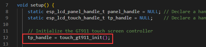
Support
Monday-Friday (9:30-6:30) Saturday (9:30-5:30)
Email: services01@spotpear.com
[Tutorial Navigation]
- Introduction
- Pinouts
- Usage Instructions
- Working with Arduino
- Working with ESP-IDF
- Environment Setup
- Run the First ESP-IDF Demo
- New Project
- Create Demo
- Modify COM Port
- Modify Driver Object
- Other Status Bar Functions
- Compile, Flash and Serial Port Monitor
- Use the IDF Demos
- Demo
- PlatformIO Development
- Resources
- Schematic Diagram
- Demo
- Datasheets
- Software Tools
- Other Resource Links
- FAQ
- Question: ESP32-S3-Touch-LCD-7B shows no response after uploading an Arduino demo for RGB screen displaying?
- Question: Why are all libraries installed, and the flashing LVGL program reports an error missing lv_cong.h?
- Question: Why does error "fatal error:esp_ memory_ utils.h:No such file or directory" occur when compiling demos using the Arduino IDE?
- Question:Can CAN communication use debugging tools to send continuous frames?
- Question: What should I do if ESP-IDF flashing fails?
- Question: What should I do if I can't find the AppData folder?
- Question: How to check the COM port?
- Question: How to deal with the first compilation of the program being extremely slow?
- Question: How to solve the problem that the program is flashed successfully but there is no display on LCD?
- Question: Why does the program flashing fail when using a MAC device?
- Question: How to use SquareLine Studio to design interfaces?
- Question: How to port the provided lib libraries? Or how to develop my own LCD screen? How to drive?
- Question: What should I do if WiFi reconnecting causes drifting?
- Question: How to use LVGL for boards without touch?
- Support