


- sales/support
Google Chat:---
- sales
+86-0755-88291180
- sales01
sales@spotpear.com
- sales02
dragon_manager@163.com
- support
tech-support@spotpear.com
- CEO-Complaints
zhoujie@spotpear.com
- Only Tech-Support
WhatsApp:13246739196
- Purchase/Shipping/Refund
WhatsApp:13424403025
- HOME
- >
- ARTICLES
- >
- Common Moudle
- >
- ESP
ESP32-S3-CAM-OV5640 User Guide
Features
Powered by the ESP32-S3R8 high-performance Xtensa 32-bit LX7 dual-core processor, with a main frequency of up to 240 MHz
Supports 2.4GHz Wi-Fi (802.11 b/g/n) and Bluetooth 5 (LE) with an onboard antenna
Features 512 KB of internal SRAM and 384 KB of ROM, with 8 MB of stacked PSRAM and an external 16 MB Flash
Utilizes a Type-C interface, improving user convenience and device compatibility
Onboard 24PIN DVP camera interface, compatible with multiple camera modules
Onboard 18PIN screen interface, supporting SPI and QSPI
Equipped with a dual-microphone array for audio algorithms such as noise reduction and echo cancellation, suitable for accurate speech recognition and near-field/far-field wake-up applications
Onboard PWR and BOOT side buttons, configurable for custom function development
Onboard 3.7V GH1.25 lithium battery charge/discharge interface
Camera Parameter Comparison
Model Max Resolution Output Interface Output Format Lens Size Focal Length Aperture Field of View OV5640 Camera 2592×1944 DVP RGB565
YUV
YCbCr4221/4inch 4.1mm 2.8 D:68° H:55° V:42° OV3660 Camera 2048×1536 DVP 8/10-bit Raw RGB data
JPEG compression
YUV/YCbCr422
RGB565- 3.2mm 2.4 D:68° GC2145 Camera 1616×1232 DVP RGB565
YCbCr422
8-bit Raw RGB data1/5inch 2.38mm 2.4 D:68° H:60° V:46.8° GC0308 Camera 648×488 DVP Grayscale
YCbCr422
RGB5651/6.5inch 2.5mm 2.4 D:58° H:46° V:35°
Onboard Resources
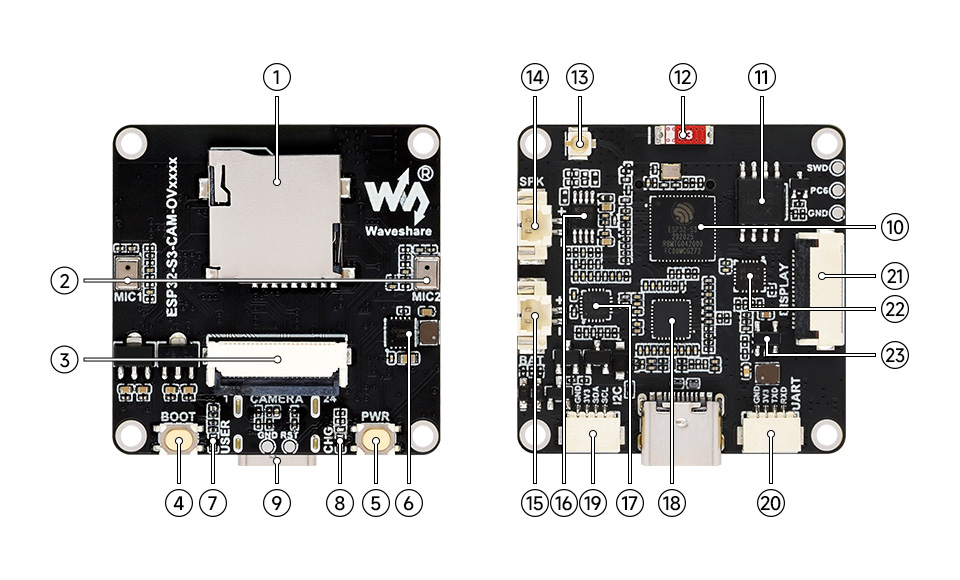
- TF card slot
- Dual-microphone array
- DVP camera interface
- BOOT button
- PWR button
- ETA6098 charging management chip
- USER indicator
- Charging indicator
- Type-C interface
- ESP32-S3R8
- 16MB Flash
- Onboard ceramic antenna
- IPEX 1 connector (Default onboard antenna; can be switched to an external antenna via resoldering an onboard resistor)
- Speaker header (3W 4Ω output power)
- Battery header (GH1.25 2PIN connector for 3.7V Lithium Batt, supports charging and discharging)
- NS4150B amplifier chip
- ES8311
- ES7210
- I2C header
- UART header
- LCD 18PIN interface
- CH32V003F4U6 I/O expander chip
- MP1605 power module
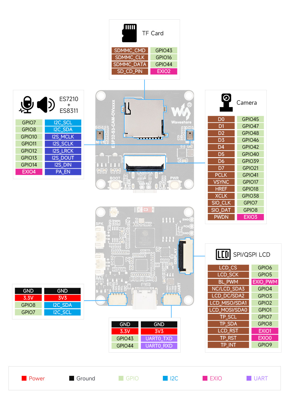
Interface Definition
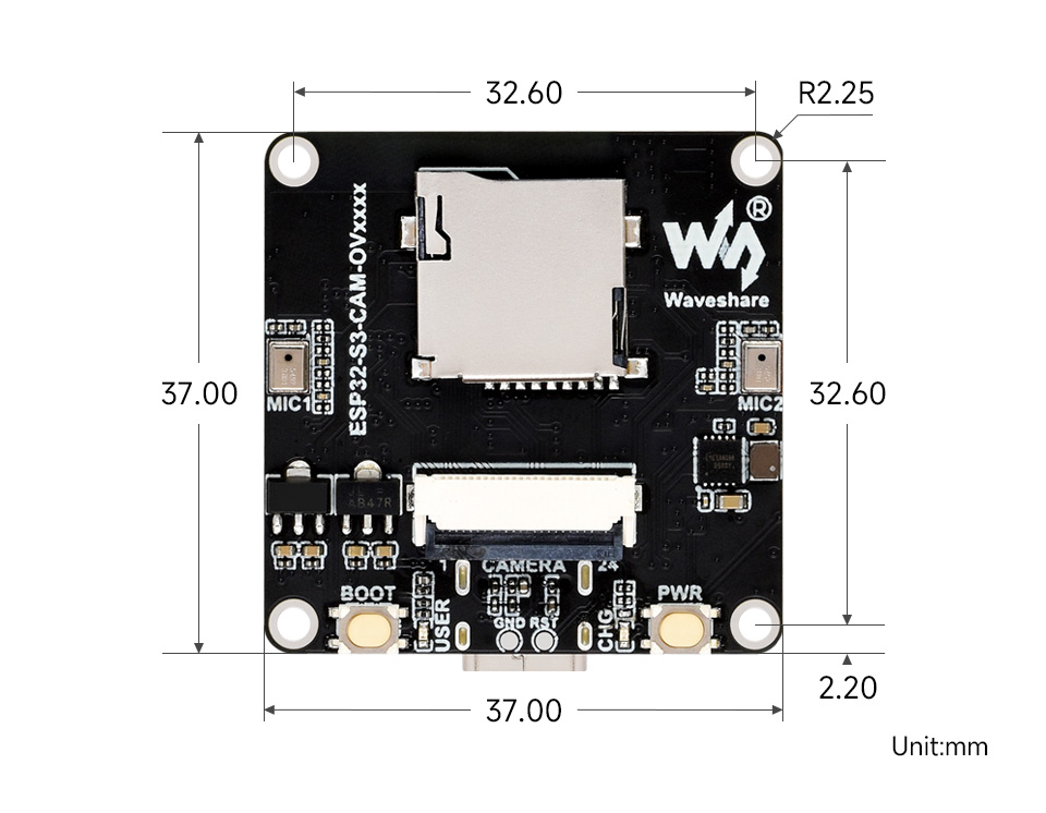
Dimensions
User Guide
To help users quickly understand the various functions of the product, we provide a series of test routines for customers to learn how to use each interface. In addition to the ESP32-S3-CAM-OVxxxx main unit and its included cables, the following components are required to run the examples:
Component Preparation
- ESP32-S3-CAM-OVxxxx ×1
- TF card ×1 (not required, needed only for TF card examples)
- Screen, supports 1.83, 2inch, 2.8inch, 3.5inch ×1
Precautions
- When using, pay attention to the PCB antenna area. Avoid having other metal or plastic parts in contact with the PCB antenna.
- The screen and camera occupy most of the GPIOs. The development board uses the
CH32V003chip as an I/O expander for control functions such as reset and backlight on/off. - The GH1.25 lithium battery connector supports only a single-cell 3.7 V lithium battery. Do not connect multiple battery packs simultaneously for charging or discharging. A single-cell capacity of 2000 mAh or less is recommended.
⚠️ USB Download Precautions (Important)
If the port is not recognized, please enter Boot mode:
- Press and hold the BOOT button
- Connect the USB cable to the computer
- Release the BOOT button
After the download is complete, restart the board to run the program.
Example Introduction
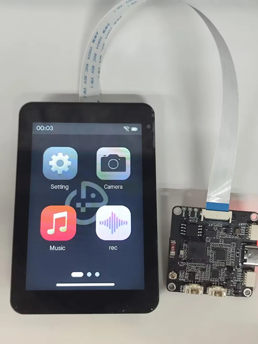
- The firmware uses the Brookesia component, showcasing various app-style applications, including Settings, Camera, Music Player, Recorder, SquareLine, XiaoZhi AI, etc.
Firmware Download
The example programs are located in the
Firmwaredirectory of the demo package.Select the firmware corresponding to your screen for flashing. For example, ESP32-S3-CAM-OVxxxx-Factory-LCD_1_83.bin supports the 1.83 screen
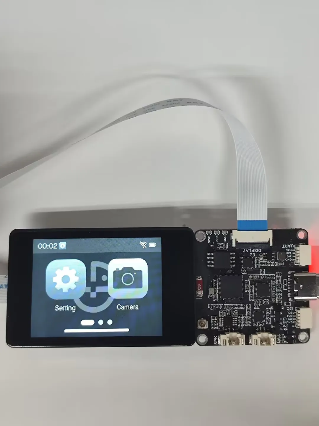
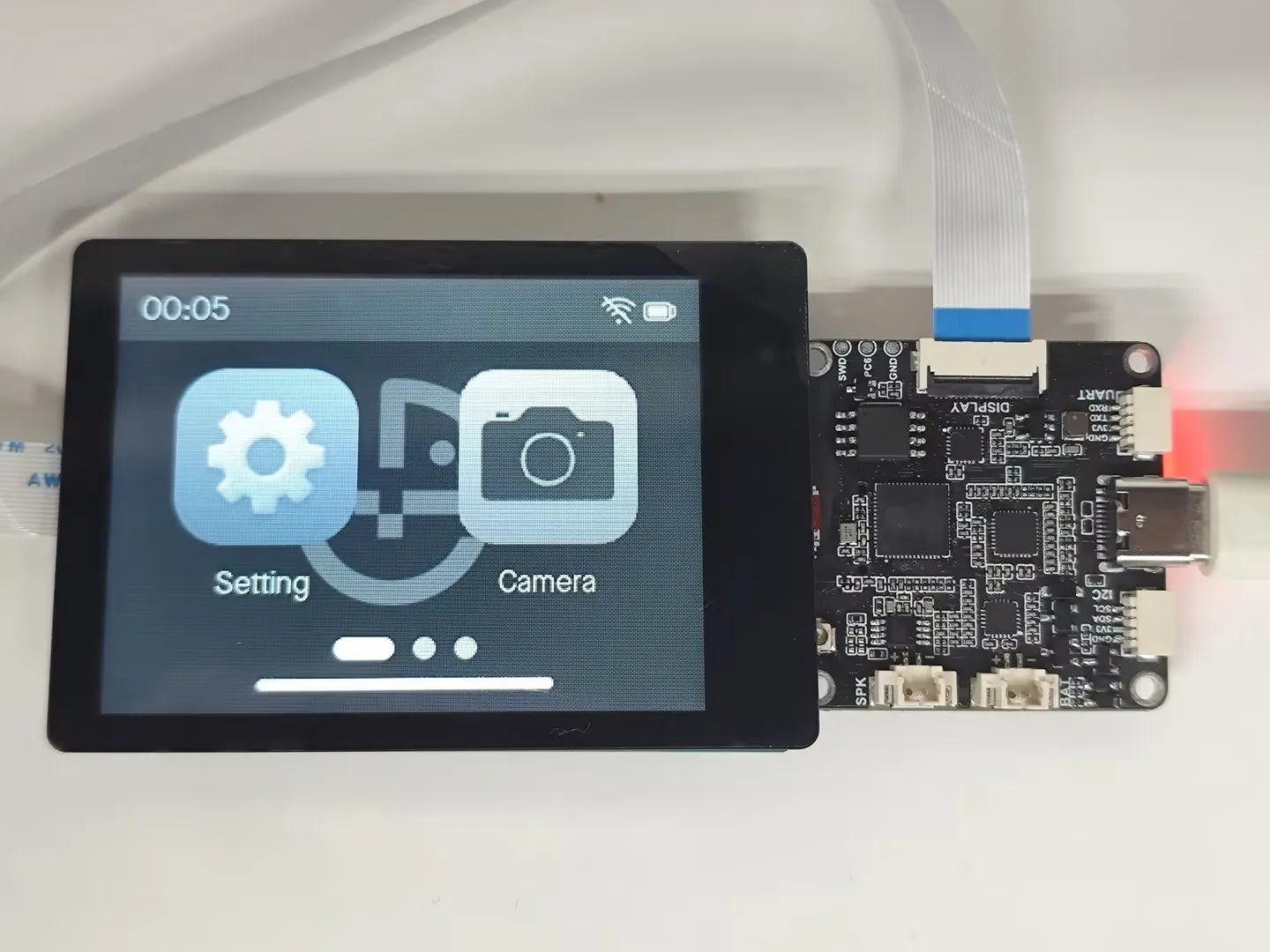
The images below show the effect after flashing the firmware on 1.83, 2inch, 2.8inch, 3.5inch
App Example Introduction
- To exit an app, swipe up from the bottom of the screen
- Swipe up from the bottom and pause in the middle of the screen to view recently used apps. Swipe up again on an app preview to close it
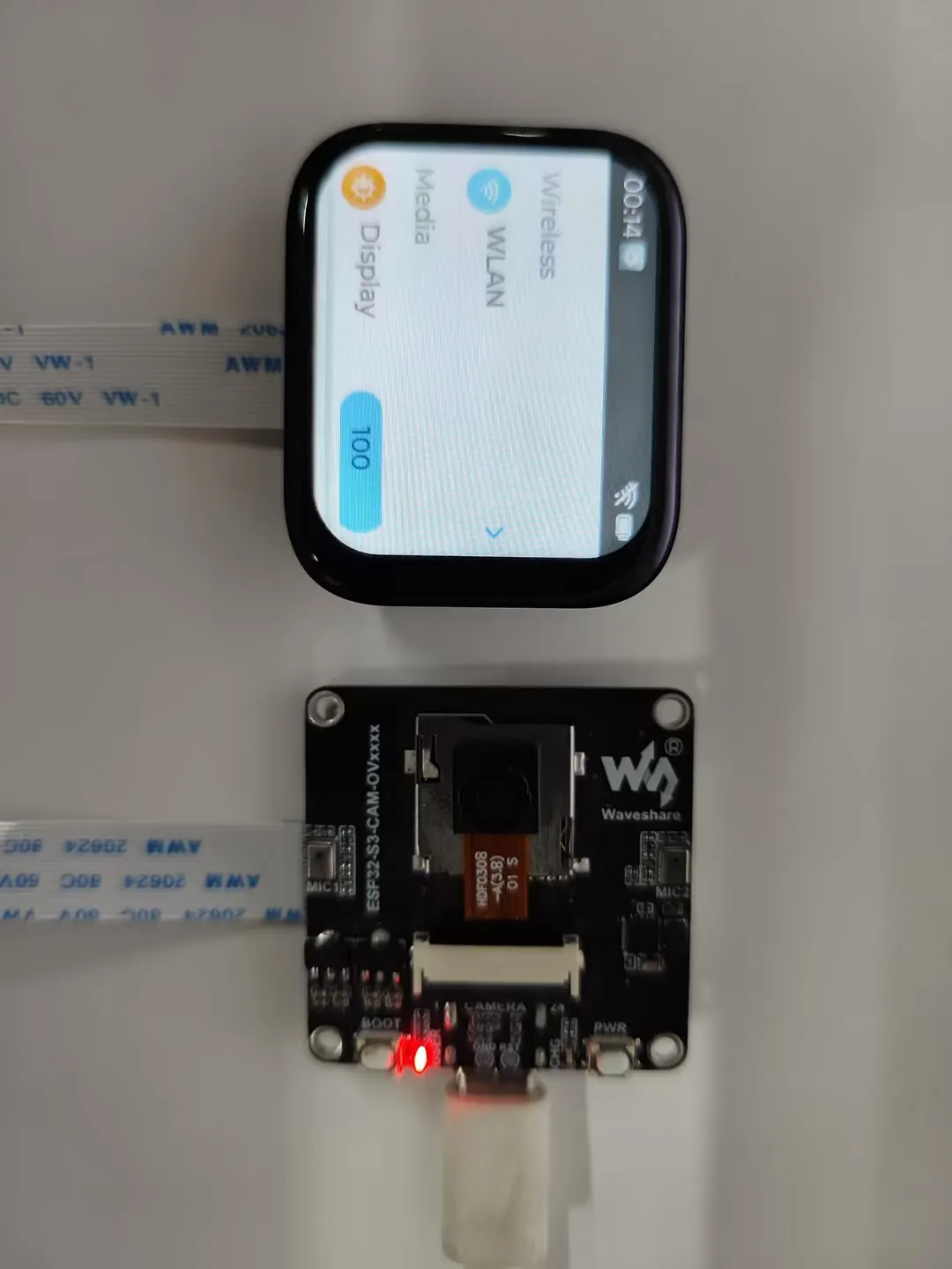
Settings App
Features Wi-Fi scanning and network configuration. Click
WIFIon the interface, thenwifi configto scan a QR code for network configurationAllows adjustment of display brightness and volume
Displays the battery ADC voltage
Product information screen where you can view the MAC address
Camera App
Supports (OV5640, OV3660, GC2145, GC0308). More cameras are being adapted
Tap the app icon to start streaming the image to the screen immediately. Tap anywhere on the screen to exit image display. You can also view camera information, as well as perform horizontal mirror and vertical flip operations
Music APP
Simulates a music player interface. This app requires an inserted memory card with MP3 files placed in the
musicdirectory to function correctly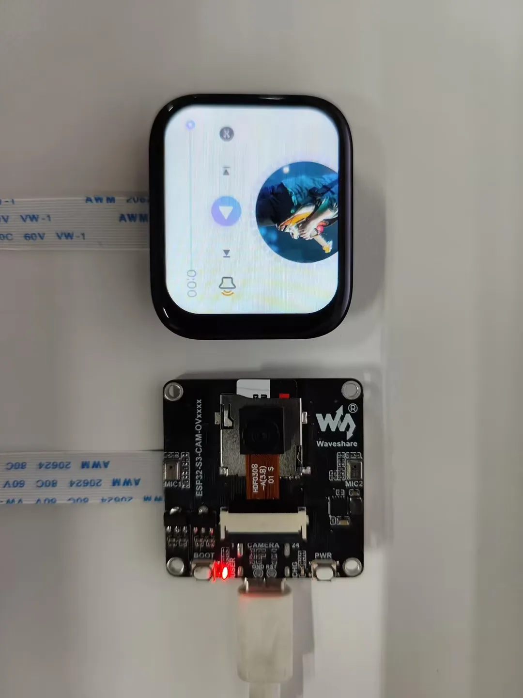
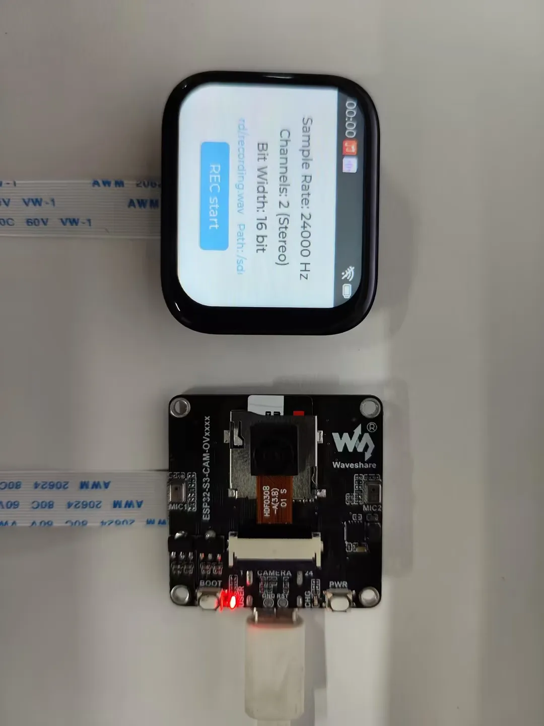
Recorder APP
This demo allows testing dual-microphone recording. Click the start button to begin recording, click again to stop recording. The app will then automatically play back the recorded audio
The recorded audio file is saved in the root directory of the memory card
Squareline
This example demonstrates an LVGL demo created with SquareLine Studio
XiaoZhi AI APP
Tap the app icon to enter the XiaoZhi AI application. It is consistent with the version adapted for the XiaoZhi official website and operates in the same way. Press and hold the Boot button to return to the Brookesia interface
Working with Arduino
This chapter contains the following sections. Please read as needed:
Arduino Getting Started
New to Arduino ESP32 development and looking for a quick start? We have prepared a comprehensive Getting Started Tutorial for you.
- Section 0: Getting to Know ESP32
- Section 1: Installing and Configuring Arduino IDE
- Section 2: Arduino Basics
- Section 3: Digital Output/Input
- Section 4: Analog Input
- Section 5: Pulse Width Modulation (PWM)
- Section 6: Serial Communication (UART)
- Section 7: I2C Communication
- Section 8: SPI Communication
- Section 9: Wi-Fi Basics
- Section 10: Web Server
- Section 11: Bluetooth
- Section 12: LVGL GUI Development
- Section 13: Comprehensive Project
Note: This tutorial uses the ESP32-S3-Zero as a reference example, and all hardware code is based on its pinout. Before you start, we recommend checking the pinout of your development board to ensure the pin configuration is correct.
Setting Up Development Environment
1. Installing and Configuring Arduino IDE
Please refer to the tutorial Installing and Configuring Arduino IDE to download and install the Arduino IDE and add ESP32 support.
2. Installing Libraries
To run the demo, you need to install the corresponding library.
You can click here to download the demo package for the ESP32-S3-CAM-OVxxxx development board. The arduino\libraries directory within the package already includes all the library files required for this tutorial.
| Library/File Name | Description | Version | Installation Method |
|---|---|---|---|
| es7210 | Audio ADC driver | —— | Manual Installation |
| es8311 | Audio DAC driver | —— | Manual Installation |
| lvgl | LVGL graphics library | v8.4.0 | Via Library Manager or Manual Installation |
| ESP32-audioI2S-master | Audio playback component | v3.4.4 | Via Library Manager or Manual Installation |
There are strong dependencies between versions of LVGL and its driver libraries. For example, a driver written for LVGL v8 may not be compatible with LVGL v9. To ensure that the examples can be reproduced reliably, it is recommended to use the specific versions listed in the table above. Mixing different versions of libraries may lead to compilation failures or runtime errors.
Installation Steps:
Navigate to the downloaded demo package.
Copy all the folders (e.g., ESP32-audioI2S-master, lvgl) from its
Arduino\librariesdirectory to your Arduino libraries folder.INFOThe path to the Arduino libraries folder is typically:
c:\Users\<username>\Documents\Arduino\libraries.You can also locate it in the Arduino IDE by going to File > Preferences and checking the "Sketchbook location". The libraries folder is the
librariessubfolder within this path.For other installation methods, please refer to: Arduino Library Management Tutorial.
Demo
The Arduino demos are located in the Arduino/examples directory of the demo package.
| Demo | Basic Program Description | Dependency Library |
|---|---|---|
| 01_lvgl_example | Demonstrates basic graphics library functions; also can be used to test basic display performance | lvgl |
| 02_CameraWebServer | Web camera test. Connects to Wi-Fi, creates an HTTP server, and captures camera images | —— |
| 03_audio_out_no_tf | Audio playback test | es8311 |
| 04_SDMMC_Test | TF card mounting and file read/write test | LVGL,SensorLib |
| 05_audio_out_tf | LVGL demonstration | LVGL, Arduino_DriveBus, Adafruit_XCA9554 |
| 06_esp_sr | ES7210 driver example, capturing human voice for detection | —— |
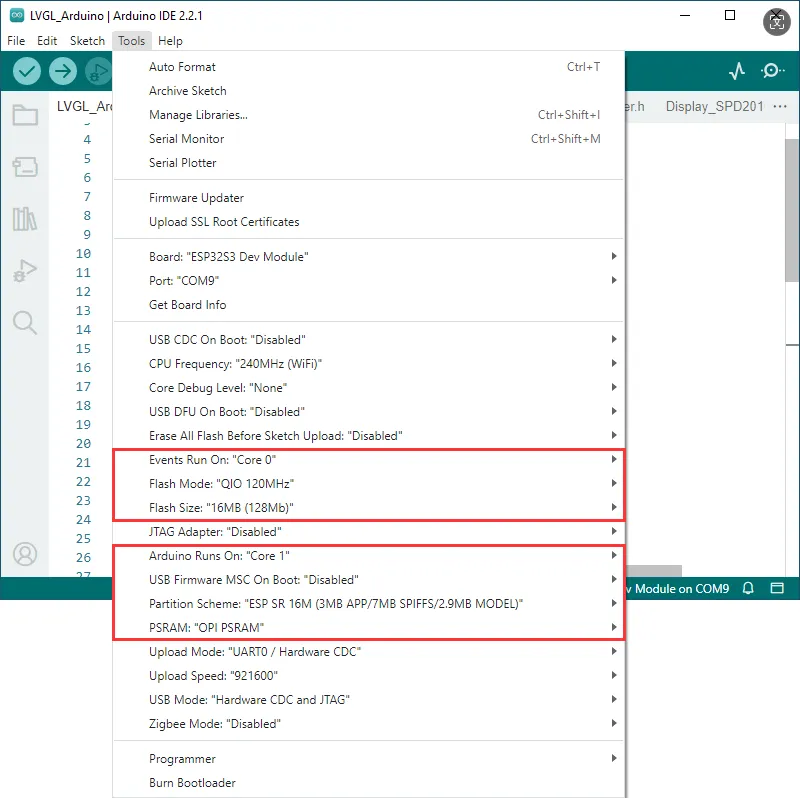
Arduino Project Parameter Settings
- If the example being flashed contains a speech recognition model, select "ESP SR 16M (3MB APP/7MB SPIFFS/2.9MB MODEL)" for the Partition Scheme.
- If the example being flashed does not contain a speech recognition model, select "16M Flash (3MB APP/9.9MB FATFS)" or another appropriate scheme.
01_lvgl_example
Demo Description
- This example demonstrates how to drive the display using Arduino and run an LVGL example program
Hardware Connection
- Connect the development board to the computer
Code Analysis
Initialize I2C and backlight:
DEV_I2C_Init();

IO_EXTENSION_Init();
IO_EXTENSION_Output(IO_EXTENSION_IO_6, 1);
IO_EXTENSION_Pwm_Output(100);
Initialize the display, touch, and LVGL:
lcd_driver_init();
touch_driver_init();
lvgl_driver_init();
Load the LVGL demo:
lvgl_port_lock(0);

  lv_demo_widgets();
// lv_demo_benchmark();
// lv_demo_keypad_encoder();
// lv_demo_music();
// lv_demo_stress();

lvgl_port_unlock();
Operation Result
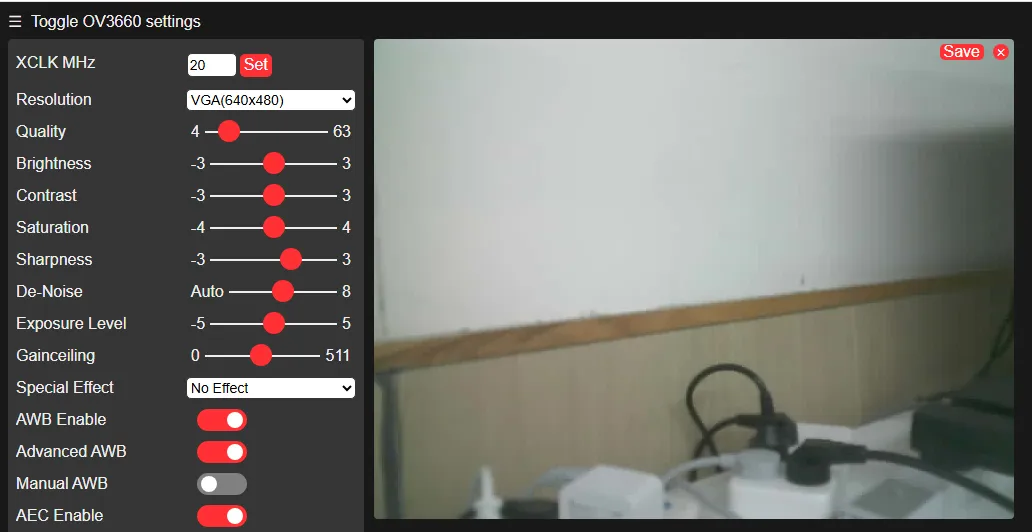
02_CameraWebServer
Demo Description
- This example is a comprehensive program combining camera and HTTP server functionality. You can access the camera video stream through a browser
Hardware Connection
- Connect the camera (supports GC0308, GC2145, OV5640, OV3660)
- Connect the development board to the computer
Code Analysis
Initialize the camera:
esp_err_t err = esp_camera_init(&config);
if (err != ESP_OK) {
  esp_camera_deinit();
  Serial.printf("Camera init failed with error 0x%x", err);
  config.frame_size = FRAMESIZE_QVGA;
  config.pixel_format = PIXFORMAT_RGB565;
  esp_camera_init(&config);
}
Enter the SSID and password to connect to Wi-Fi:
WiFi.begin(ssid, password);Start the HTTP server:
startCameraServer();
Operation Result
After powering on, wait for the Wi-Fi connection. Open the serial monitor to see the IP address, then open it in a browser

03_audio_out_no_tf
Demo Description
- This example demonstrates playing music using the ES8311 audio DAC
Hardware Connection
- Connect a speaker
- Connect the development board to the computer
Code Analysis
Initialize the I2C controller and external I/O expander:
DEV_I2C_Init();
IO_EXTENSION_Init();
IO_EXTENSION_Output(IO_EXTENSION_IO_6, 1);
Initialize ES8311:
es8311_codec_init();Initialize I2S and enable the power amplifier (PA) pin:
setupI2S();
IO_EXTENSION_Output(IO_EXTENSION_IO_4, 1);
In the loop, continuously write data to the ES8311 via I2S:
void loop() {
i2s.write((uint8_t *)audio_data, AUDIO_SAMPLES * 2);
}
Operation Result
- After flashing the program, music will start playing automatically
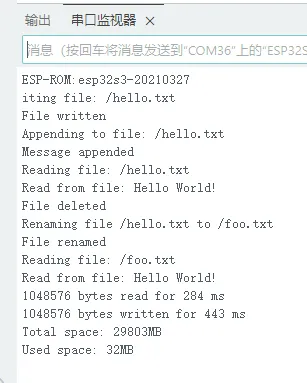
04_SDMMC_Test
Demo Description
- This example demonstrates how to mount a TF card and test file reading and writing
Hardware Connection
- Insert a TF card
- Connect the development board to the computer
Code Analysis
Set the SDIO interface pins and mount the file system:
if(!SD_MMC.setPins(clk, cmd, d0)){
      Serial.println("Pin change failed!");
      return;
  }

if (!SD_MMC.begin( "/sdcard", true)) {
    Serial.println("Card Mount Failed");
    return;
}
File read/write test:
listDir(SD_MMC, "/", 0);
createDir(SD_MMC, "/mydir");
listDir(SD_MMC, "/", 0);
removeDir(SD_MMC, "/mydir");
listDir(SD_MMC, "/", 2);
writeFile(SD_MMC, "/hello.txt", "Hello ");
appendFile(SD_MMC, "/hello.txt", "World!\n");
readFile(SD_MMC, "/hello.txt");
deleteFile(SD_MMC, "/foo.txt");
renameFile(SD_MMC, "/hello.txt", "/foo.txt");
readFile(SD_MMC, "/foo.txt");
testFileIO(SD_MMC, "/test.txt");
Serial.printf("Total space: %lluMB\n", SD_MMC.totalBytes() / (1024 * 1024));
Serial.printf("Used space: %lluMB\n", SD_MMC.usedBytes() / (1024 * 1024));
Operation Result
05_audio_out_tf
Demo Description
- This example demonstrates playing MP3 audio from a TF card
Hardware Connection
- Insert a TF card with an audio file named ff-16b-1c-44100hz.mp3 in the root directory
- Connect a speaker
- Connect the development board to the computer
Code Analysis
Initialize I2S and the audio decoder library, and set the playback path:
audio.setPinout(I2S_BCK_PIN, I2S_LRCK_PIN, I2S_DOUT_PIN,I2S_MCLK_PIN);
audio.connecttoFS(SD_MMC, "ff-16b-1c-44100hz.mp3");
Operation Result
- After flashing the program, MP3 music will play automatically
06_esp_sr
Demo Description
- This example demonstrates using the ES7210 audio ADC chip for voice wake-up and speech recognition
Hardware Connection
- Connect the development board to the computer
Code Analysis
Initialize I2S and the ES7210 audio ADC:
Wire.begin(I2C_PIN_SDA, I2C_PIN_SCL);
es7210_init();
i2s.setPins(I2S_PIN_BCK, I2S_PIN_WS, I2S_PIN_DOUT, I2S_PIN_DIN, I2S_PIN_MCK);
i2s.setTimeout(1000);
i2s.begin(I2S_MODE_STD, 16000, I2S_DATA_BIT_WIDTH_16BIT, I2S_SLOT_MODE_STEREO);
Register callbacks for voice wake-up and speech recognition events, then start ESP-SR:
 ESP_SR.onEvent(onSrEvent);
ESP_SR.begin(i2s, sr_commands, sizeof(sr_commands) / sizeof(sr_cmd_t), SR_CHANNELS_STEREO, SR_MODE_WAKEWORD);
Operation Result
ESP-IDF
This chapter contains the following sections. Please read as needed:
Setting Up Development Environment
For the ESP32-S3-CAM-OVxxxx development board, ESP-IDF version V5.5.1 or above is required.
The following guide uses Windows as an example, demonstrating development using VS Code + the ESP-IDF extension. macOS and Linux users should refer to the official documentation.
Install the ESP-IDF Development Environment
Download the installation manager from the ESP-IDF Installation Manager page. This is Espressif's latest cross-platform installer. The following steps demonstrate how to use its offline installation feature.
Click the Offline Installer tab on the page, then select Windows as the operating system and choose your desired version from the filter bar.

After confirming your selection, click the download button. The browser will automatically download two files: the ESP-IDF Offline Package (.zst) and the ESP-IDF Installer (.exe).

Please wait for both files to finish downloading.
Once the download is complete, double-click to run the ESP-IDF Installer (eim-gui-windows-x64.exe).
The installer will automatically detect if the offline package exists in the same directory. Click Install from archive.

Next, select the installation path. We recommend using the default path. If you need to customize it, ensure the path does not contain Chinese characters or spaces. Click Start installation to proceed.

When you see the following screen, the ESP-IDF installation is successful.

We recommend installing the drivers as well. Click Finish installation, then select Install driver.

Install Visual Studio Code and the ESP-IDF Extension
Download and install Visual Studio Code.
During installation, it is recommended to check Add "Open with Code" action to Windows Explorer file context menu to facilitate opening project folders quickly.
In VS Code, click the Extensions icon
 in the Activity Bar on the side (or use the shortcut Ctrl + Shift + X) to open the Extensions view.
Enter ESP-IDF in the search box, locate the ESP-IDF extension, and click Install.

For ESP-IDF extension versions ≥ 2.0, the extension will automatically detect and recognize the ESP-IDF environment installed in the previous steps, requiring no manual configuration.
Demo
The ESP-IDF demos are located in the ESP-IDF directory of the demo package.
| Demo | Basic Description |
|---|---|
| 01_simple_video_server | Create multiple HTTP servers on different ports on the local network, accessible via a web browser, providing video streaming functionality |
| 02_esp_sr | Demonstrate speech recognition and voice wake-up functions using the ESP-SR component |
| 03_audio_play | Scan the TF card and play MP3 audio |
| 04_dvp_camera_display | Display the camera feed on the LCD screen |
| 05_lvgl_brookesia | Show LVGL APP style UI using the Brookesia component |
| 06_usb_host_uvc | Simulate a UVC device, demonstrating USB camera functionality |
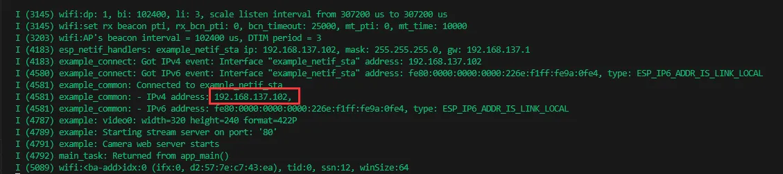
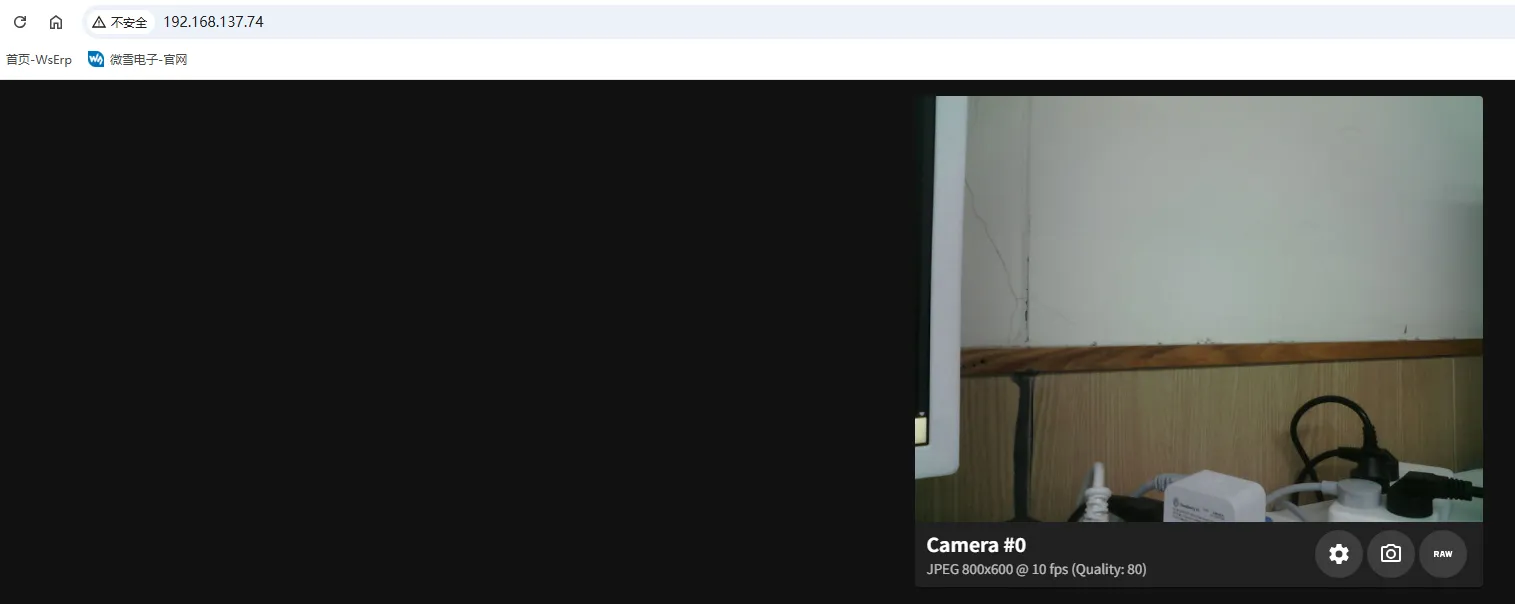
01_simple_video_server
Demo Description
- This example demonstrates creating an HTTP server, accessing it via a browser, and obtaining a video stream
Hardware Connection
- Connect the development board to the computer
- Camera: Supports GC0308, GC2145, OV5640, OV3660
Code Analysis
example_connect(): Initialize Wi-Fi connection- Set SSID and password in the menuconfig configuration
- Default SSID: WSTEST
- Default password: waveshare0755
start_cam_web_server(): Initialize the HTTP server and camera- Initialize the camera first. If an unsupported camera or format is detected, an error will be reported and the program will exit
- Wait for the camera to initialize successfully, then initialize the HTTP server
Operation Result
- This demo will not light up the screen
- Check the serial monitor for the printed IP address
- Open the IP address in a browser. Ensure you are on the same local network.
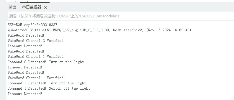
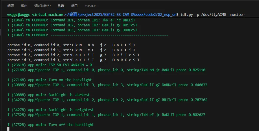
02_esp_sr
Demo Description
- This example demonstrates offline voice wake-up and speech recognition using the ESP-SR component
Hardware Connection
- Connect the development board to the computer
- Do not block the microphone
Code Analysis
Speech_Init(): Initialize the microphone and create recognition tasks- Obtain the microphone control handle via
bsp_audio_codec_microphone_init() - Create data reading and detection/recognition tasks
- Obtain the microphone control handle via
Speech_register_callback(): Register a callback function for recognition events- Events can be obtained within the callback function
Operation Result
- This demo will not light up the screen
- Check the serial monitor for voice wake-up and recognition results
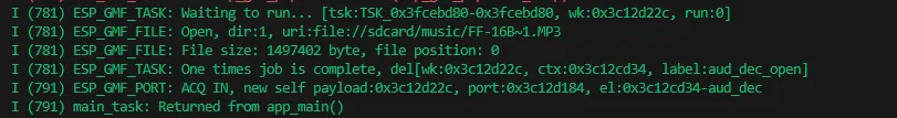
03_audio_play
Demo Description
- This example demonstrates playing MP3 audio files from a TF card
Hardware Connection
- Insert a memory card with an MP3 file placed in the root directory
- Connect a speaker
- Connect the development board to the computer
Code Analysis
bsp_io_expander_init();: Initialize the external I/O expander- Initialize the PA control pin to control audio output
bsp_sdcard_mount(): Mount the TF cardSearch_Music(): Search for and save the paths of MP3 files on the TF cardAudio_Play_Init(): Initialize the audio playerVolume_Adjustment(): Set the volume levelAudio_Play_Music(): Play the MP3 file
Operation Result
- This demo will not light up the screen
- After running, it will automatically search for MP3 files on the TF card and play them
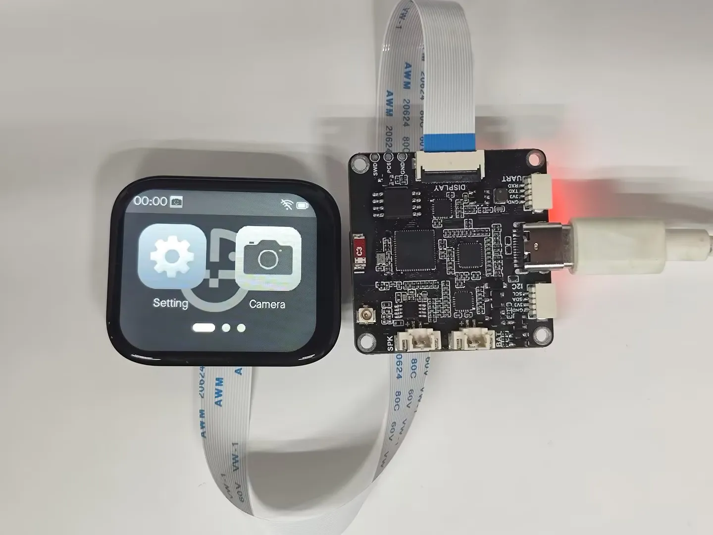
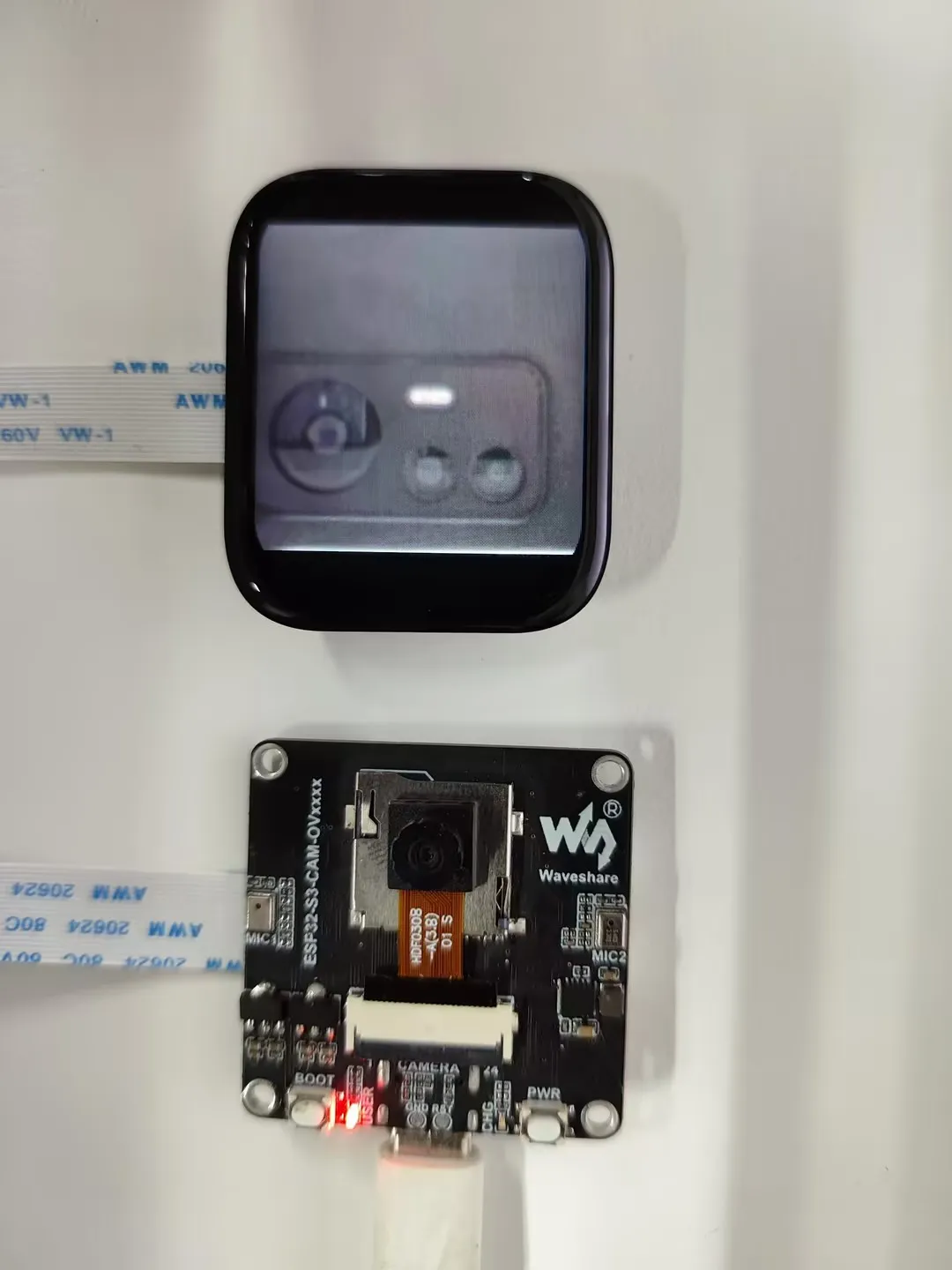
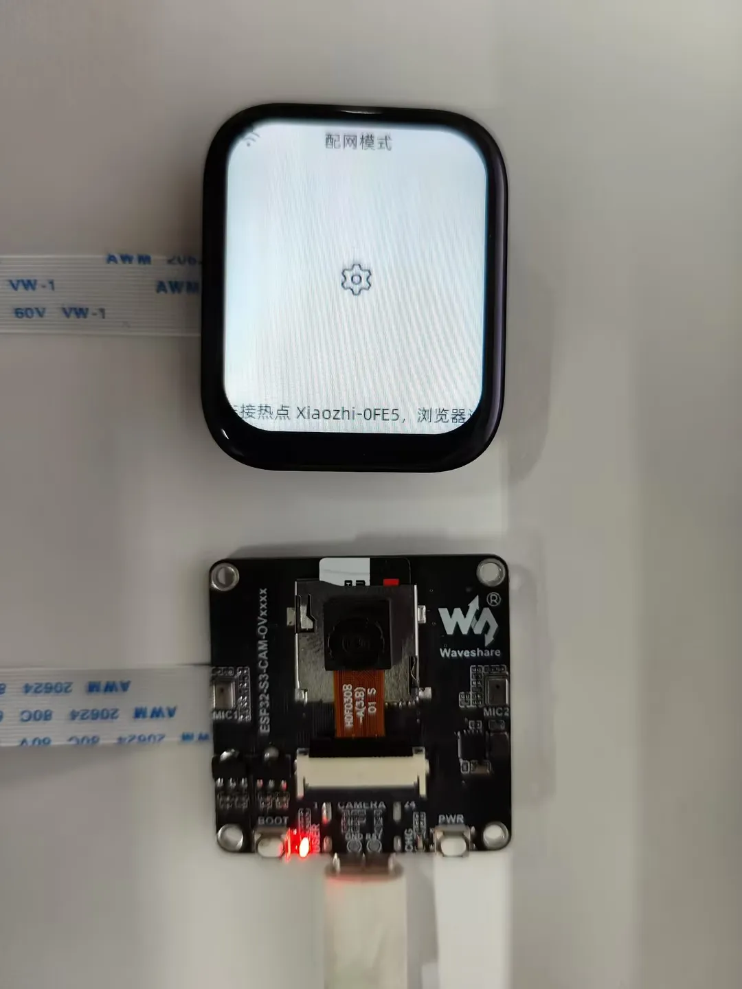
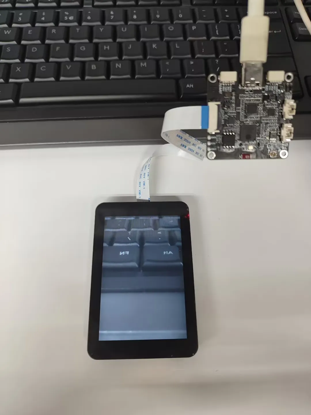
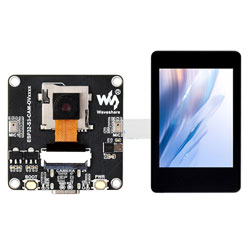
04_dvp_camera_display
Demo Description
- This example is an app-style UI + camera demo. Tapping the camera app displays the image on the screen
Hardware Connection
- Connect a DVP camera: Supports GC0308, GC2145, OV5640, OV3660
- Connect a screen, supports 1.83, 2inch, 2.8inch, 3.5inch
- Connect the development board to the computer
Code Analysis
bsp_display_start(): BSP initializes display-related resources- Initialize the LCD screen
- Initialize LVGL
bsp_display_backlight_on(): Turn on the backlightnew ESP_Brookesia_Phone(disp): Initialize the Brookesia componentnew PhoneCameraConf(1,0);: Install the camera app
Operation Result
- Tap the camera app icon, the screen starts displaying the camera image. Tap anywhere on the screen to return to the camera settings interface
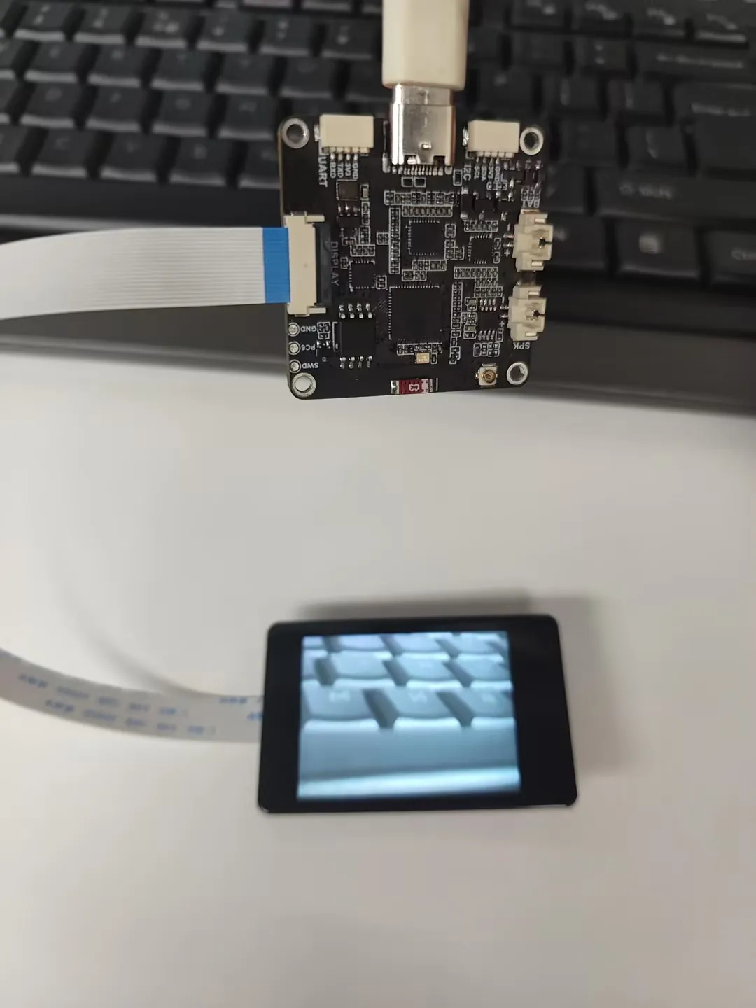 | 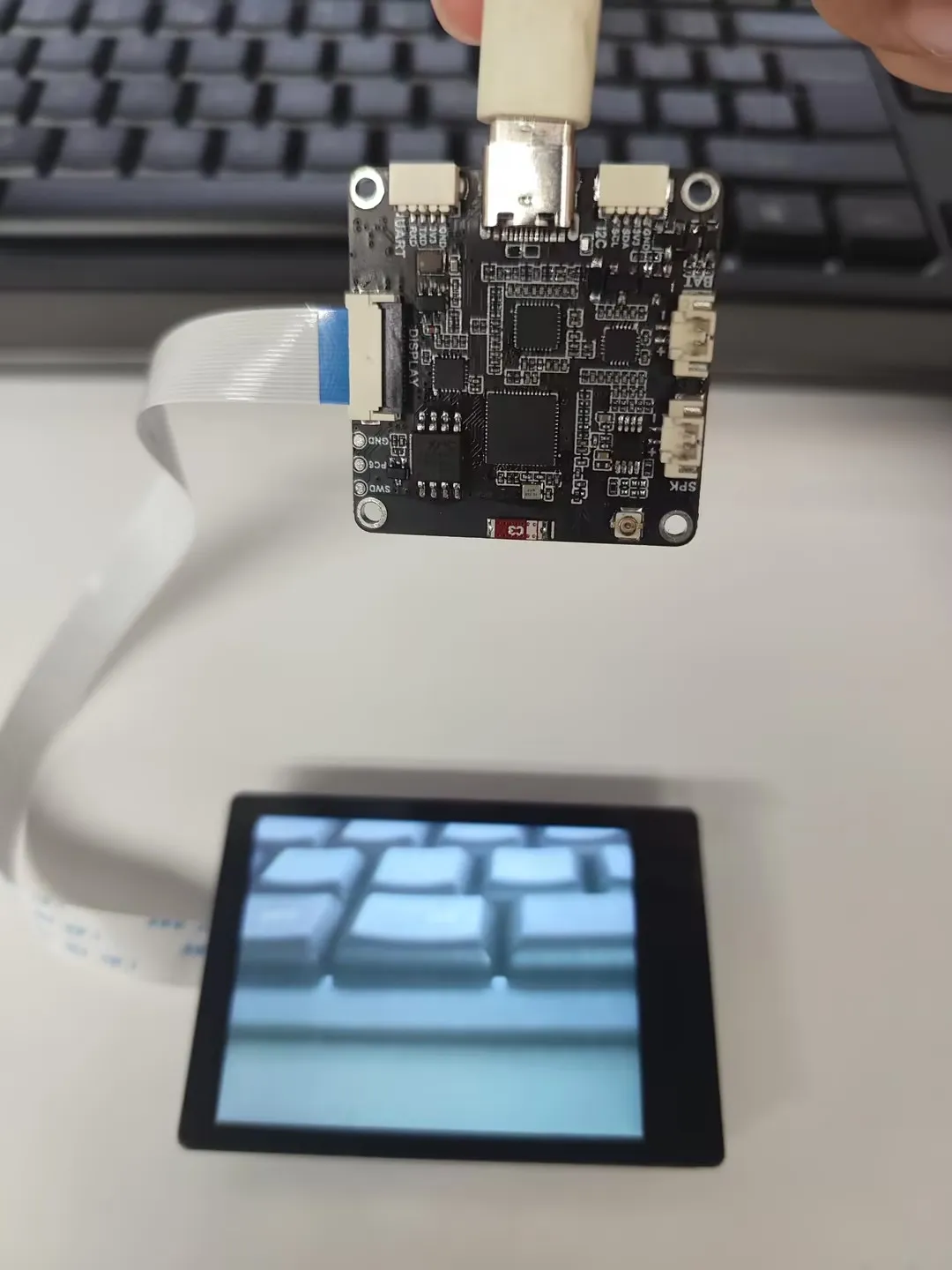 |
|---|
 | 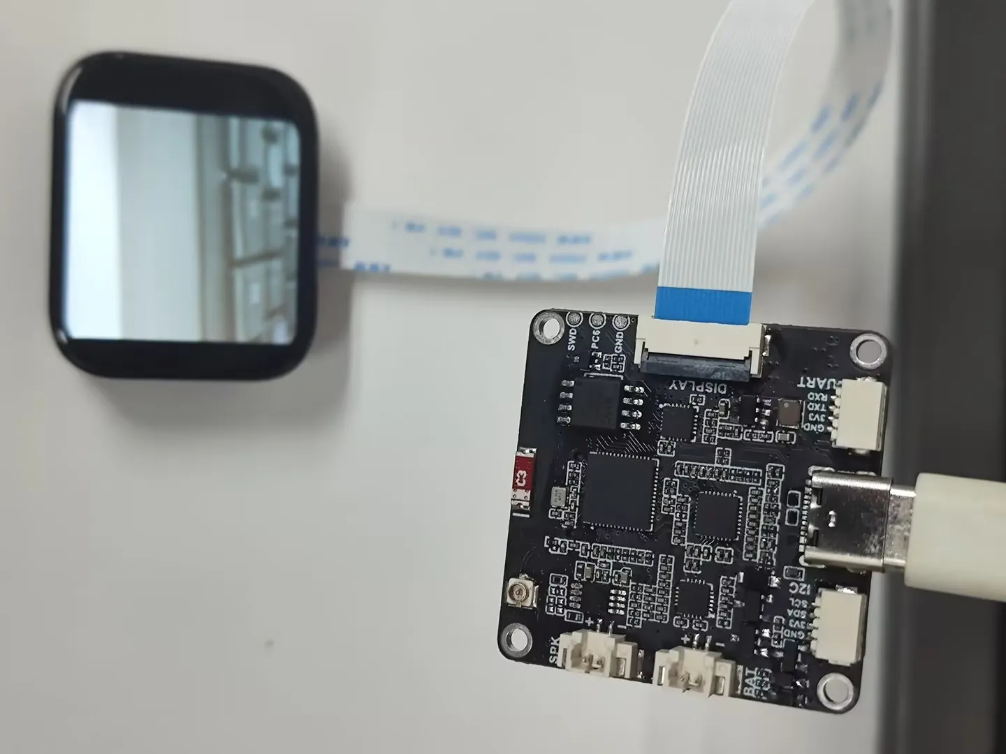 |
|---|
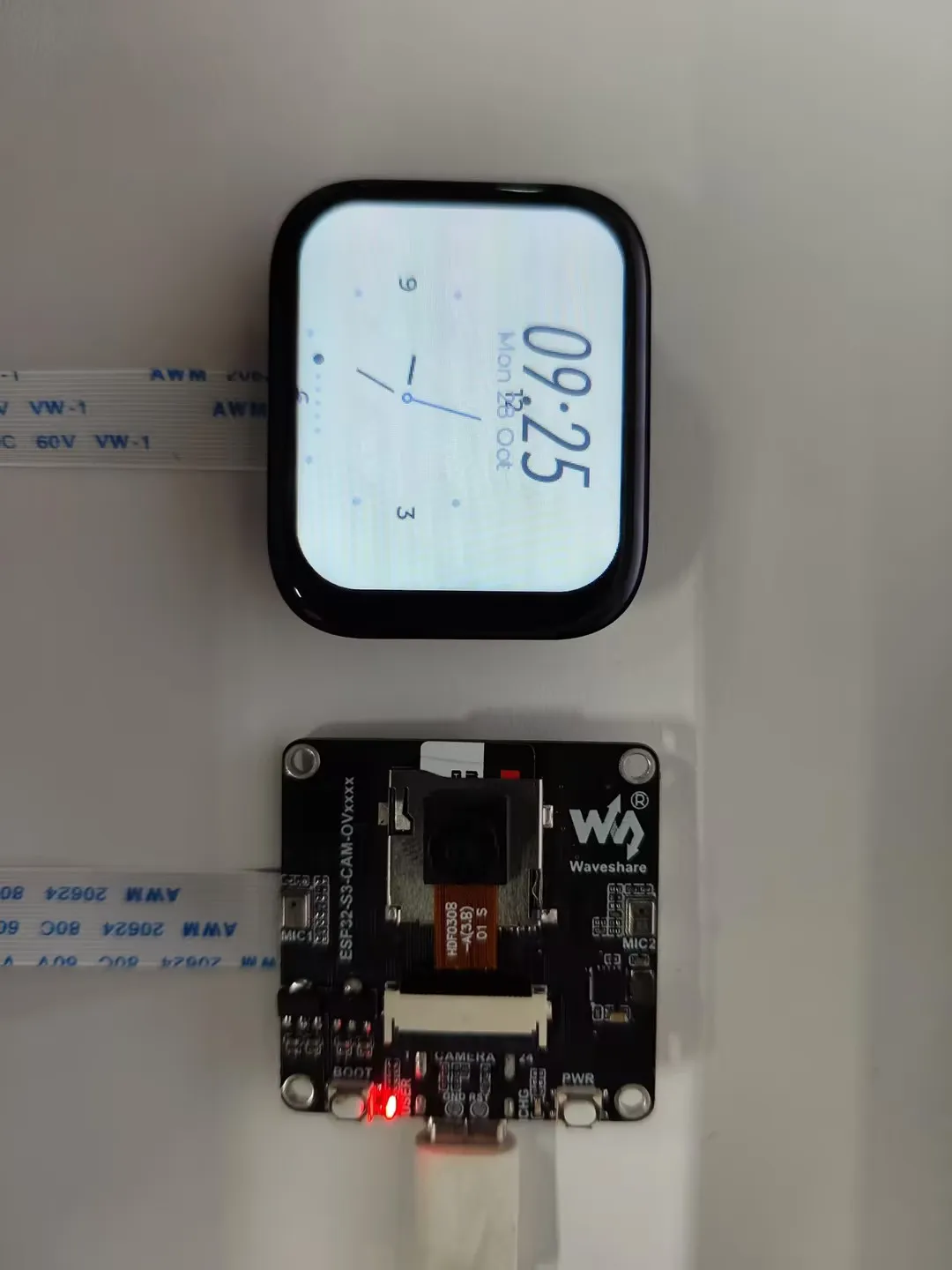
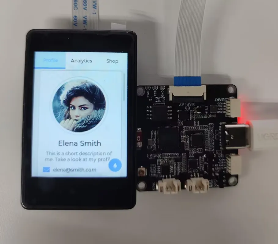
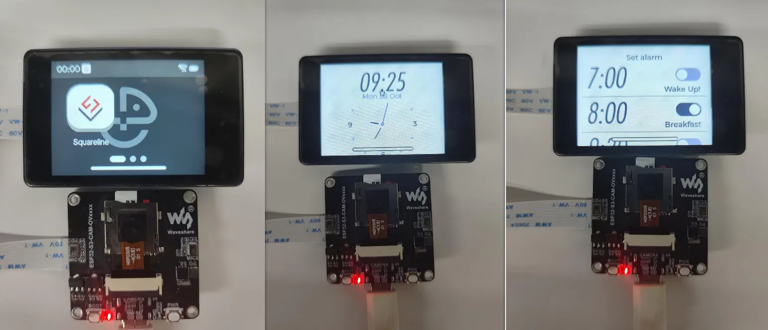
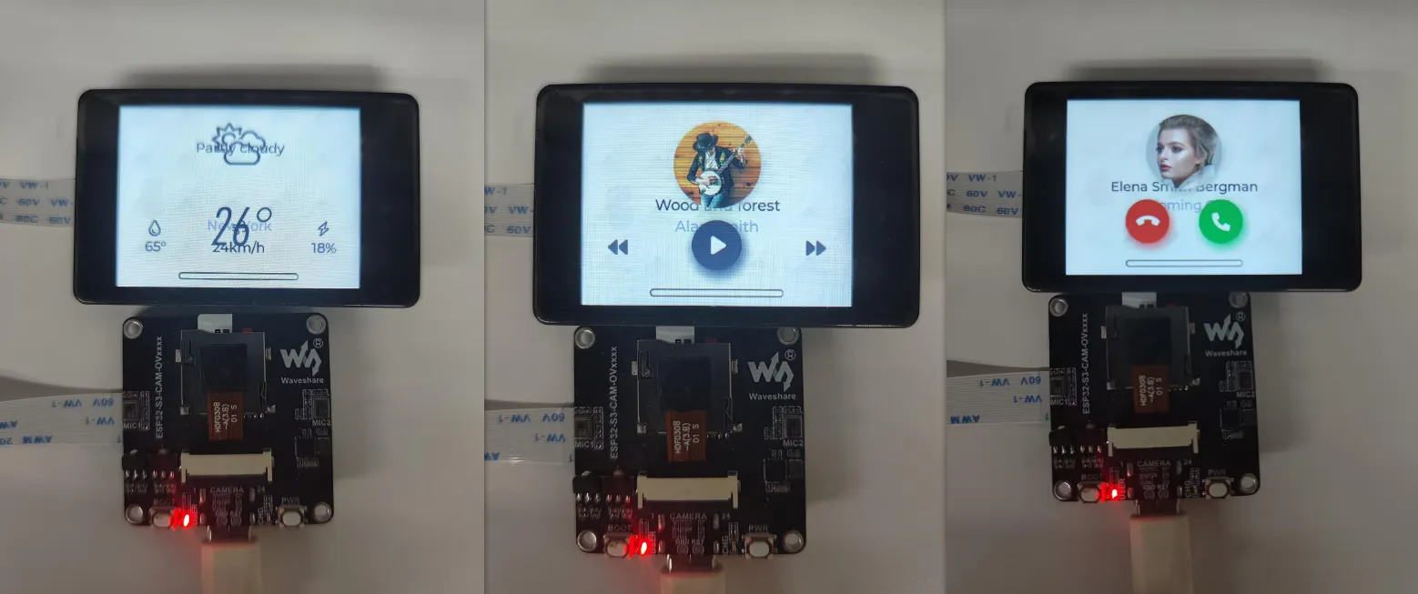
05_lvgl_brookesia
Demo Description
- This example demonstrates a complete phone-style UI system, including components such as a status bar, navigation bar, app launcher, and gesture interaction
Hardware Connection
- Connect a screen, supports 1.83, 2inch, 2.8inch, 3.5inch
- Connect the development board to the computer
Code Analysis
bsp_display_start(): BSP initializes display-related resources- Initialize the LCD screen
- Initialize LVGL
Operation Result
- The display effect is shown on a 2inch screen
06_usb_host_uvc
Demo Description
- This example simulates a UVC device, demonstrating USB camera functionality
Hardware Connection
- Connect a DVP camera: Supports OV5640, OV3660
- Connect the development board to the computer
Code Analysis
uvc_device_config(): Configure UVC device-related interface functionsuvc_device_init(): Start initializing the UVC device
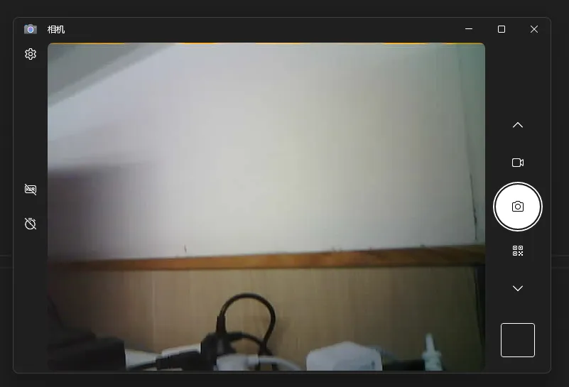
Operation Result
- Open the camera app on your computer to see the image. There may be some latency; wait a moment or try re-powering
- This demo uses the USB programming interface. When programming again, you need to hold the BOOT button to enter download mode
Resources
1. Hardware Resources
Development Board Design Files
2. Technical Manuals
Official ESP32-S3 Chip Manuals
Datasheets
3. Demo
Support
Monday-Friday (9:30-6:30) Saturday (9:30-5:30)
Email: services01@spotpear.com
[Tutorial Navigation]
- Features
- Onboard Resources
- Interface Definition
- Dimensions
- User Guide
- Working with Arduino
- Arduino Getting Started
- Setting Up Development Environment
- Demo
- ESP-IDF
- Setting Up Development Environment
- Demo
- Resources
- Support