


- sales/support
Google Chat:---
- sales
+86-0755-88291180
- sales01
sales@spotpear.com
- sales02
dragon_manager@163.com
- support
tech-support@spotpear.com
- CEO-Complaints
zhoujie@spotpear.com
- Only Tech-Support
WhatsApp:13246739196
- Purchase/Shipping/Refund
WhatsApp:13424403025
- HOME
- >
- ARTICLES
- >
- Common Moudle
- >
- ESP
ESP32-S3-Touch-LCD-1.85B User Guide
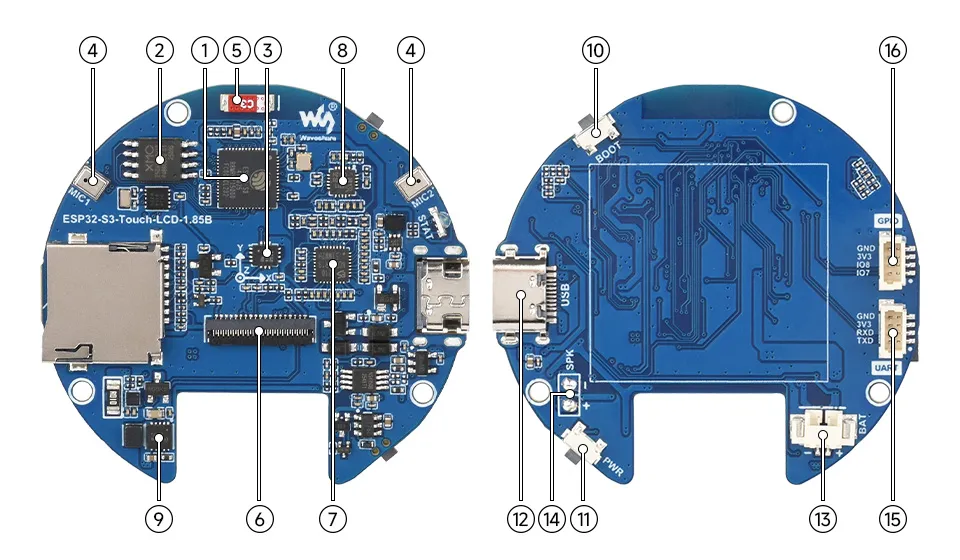
Onboard Resources
- ESP32-S3R8 Wi-Fi and Bluetooth SoC, up to 240MHz operating frequency, with onboard 8MB PSRAM
- 16MB NOR Flash
- QMI8658 Six-axis Inertial Measurement Unit (IMU), containing a 3-axis gyroscope and a 3-axis accelerometer
- Dual-microphone Design Combined with echo cancellation circuitry for higher quality audio capture
- Onboard Antenna Supports 2.4GHz Wi-Fi (802.11 b/g/n) and Bluetooth 5 (LE)
- Screen Interface
- ES7210 Echo Cancellation Chip For echo cancellation and improved audio capture accuracy
- ES8311 Audio Codec Chip
- BQ27220 Battery gauge chip
- BOOT Button Used for device startup and functional debugging
- PWR Power Button Controls power on/off and supports custom functions
- Type-C Interface ESP32-S3 USB interface for program flashing and log printing
- MX1.25 Lithium Battery Header MX1.25 2PIN connector for connecting a 3.7V lithium battery, supports charging and discharging
- Onboard Speaker Pads
- Serial Communication Interface SH1.0 4PIN connector
- I2C Interface SH1.0 4PIN connector
Peripheral Quick Reference
| Module | Device / Function | Interface | Address / Parameters | GPIO / Signals |
|---|---|---|---|---|
| LCD | ST77916 | QSPI | 360×360, common RGB565, 16-bit color depth | CS=GPIO21, PCLK=GPIO40, DATA0=GPIO46, DATA1=GPIO45, DATA2=GPIO42, DATA3=GPIO41, RST=GPIO3, BL=GPIO5 |
| Touch | CST816S capacitive touch | I2C | 7-bit address 0x15 | SCL=GPIO10, SDA=GPIO11, RST=GPIO1, INT=GPIO4 |
| IMU | QMI8658 6-axis sensor | I2C | 7-bit address 0x6B | SCL=GPIO10, SDA=GPIO11 |
| Audio Output | ES8311 audio codec | I2C + I2S | 7-bit address 0x30 | I2C SCL=GPIO10, SDA=GPIO11; MCLK=GPIO2, BCLK=GPIO48, LRCK=GPIO38, DOUT=GPIO47, DIN=GPIO39, PA=GPIO9 |
| Audio Input | ES7210 echo cancellation / dual microphone | I2C + I2S | 7-bit address 0x80 | I2C SCL=GPIO10, SDA=GPIO11; MCLK=GPIO2, BCLK=GPIO48, LRCK=GPIO38, DIN=GPIO39 |
| Battery Gauge | BQ27220 | I2C | 7-bit address 0x55 | SCL=GPIO10, SDA=GPIO11 |
| RTC | PCF85063 real-time clock | I2C | 7-bit address 0x51 | SCL=GPIO10, SDA=GPIO11, INT=GPIO6 |
| TF | SDMMC | SDMMC 4-bit | Supports SD_MMC | CLK=GPIO15, CMD=GPIO14, D0=GPIO16, D1=GPIO17, D2=GPIO12, D3=GPIO13 |
| USB Type-C | ESP32-S3 native USB | USB | Download, logging | USB_N=GPIO19, USB_P=GPIO20 |
| UART0 | Serial communication interface | UART | SH1.0 4-pin connector | U0TXD=GPIO43, U0RXD=GPIO44 |
| BOOT button | BOOT / download mode | GPIO | Pull-up, low when pressed | GPIO0 |
Pinout Definition
When using the reserved interfaces on the ESP32-S3-Touch-LCD-1.85B board, pay attention to wire colors and corresponding functions to avoid damaging the board due to incorrect wiring.
Expansion Interfaces
| Type | Signals |
|---|---|
| Power | 5V / 3V3 / GND |
| I2C | SCL(GPIO10) / SDA(GPIO11) |
| UART | TXD(GPIO43) / RXD(GPIO44) |
| USB Pads | DN(GPIO19) / DP(GPIO20) |
GPIO Allocation
The table below lists the GPIOs already occupied by onboard circuits and those brought out to expansion headers.
| GPIO | Signal Name | Connected To | Remarks |
|---|---|---|---|
| GPIO0 | BOOT | BOOT button | Strapping pin; press and hold during power-on, then release to enter download mode |
| GPIO1 | TP_RST | CST816S touch reset | - |
| GPIO2 | I2S_MCLK | ES8311 / ES7210 audio clock | - |
| GPIO3 | LCD_RST | ST77916 LCD reset | - |
| GPIO4 | TP_INT | CST816S touch interrupt | - |
| GPIO5 | LCD_BL | LCD backlight control | PWM dimming |
| GPIO6 | RTC_INT | PCF85063 real-time clock interrupt | - |
| GPIO9 | PA_CTRL | Power amplifier control | Audio output amplifier enable |
| GPIO10 | I2C_SCL | Shared I2C SCL for touch, IMU, audio, battery gauge; also brought out to I2C interface | I2C devices listed in peripheral quick reference table |
| GPIO11 | I2C_SDA | Shared I2C SDA for touch, IMU, audio, battery gauge; also brought out to I2C interface | I2C devices listed in peripheral quick reference table |
| GPIO12 | SD_D2 | TF D2 | SDMMC 4-bit |
| GPIO13 | SD_D3 | TF D3 | SDMMC 4-bit |
| GPIO14 | SD_CMD | TF CMD | SDMMC |
| GPIO15 | SD_CLK | TF CLK | SDMMC |
| GPIO16 | SD_D0 | TF D0 | SDMMC |
| GPIO17 | SD_D1 | TF D1 | SDMMC |
| GPIO19 | USB_N | USB Type-C D- | ESP32-S3 native USB |
| GPIO20 | USB_P | USB Type-C D+ | ESP32-S3 native USB |
| GPIO21 | LCD_CS | ST77916 QSPI chip select | - |
| GPIO38 | I2S_LRCK | ES8311 / ES7210 left-right clock | - |
| GPIO39 | I2S_DIN | ES8311 / ES7210 I2S data input | Recording data input |
| GPIO40 | LCD_PCLK | ST77916 QSPI clock | - |
| GPIO41 | LCD_DATA3 | ST77916 QSPI data line 3 | - |
| GPIO42 | LCD_DATA2 | ST77916 QSPI data line 2 | - |
| GPIO43 | U0TXD | Serial communication interface TXD | Debug / expansion |
| GPIO44 | U0RXD | Serial communication interface RXD | Debug / expansion |
| GPIO45 | LCD_DATA1 | ST77916 QSPI data line 1 | - |
| GPIO46 | LCD_DATA0 | ST77916 QSPI data line 0 | - |
| GPIO47 | I2S_DOUT | ES8311 I2S data output | Playback data output |
| GPIO48 | I2S_BCLK | ES8311 / ES7210 I2S bit clock | - |
Precautions
- When connecting external I2C devices, avoid address conflicts with onboard I2C addresses such as
0x15,0x6B,0x30,0x80,0x51,0x55. GPIO19/GPIO20are connected to USB Type-C and are not recommended for use as general-purpose GPIO.GPIO0is the BOOT pin; it is not recommended to use it as a general-purpose input.- GPIOs already occupied by onboard peripherals such as LCD, touch, audio, and SDMMC should not be reused, otherwise the corresponding functions may become abnormal.
LCD Screen Specifications
| Parameter | Value |
|---|---|
| Display Panel | LCD |
| Display Size | 1.85 inches |
| Resolution | 360 × 360 |
| Display Colors | 262K colors |
| Display Interface | QSPI |
| Display Driver | ST77916 |
| Touch Controller | CST816S |
| Touch Interface | I2C |
Specifications
| Parameter | Value |
|---|---|
| Interface | USB Type-C |
| Main Controller | ESP32-S3R8 |
| SRAM / ROM | 512KB SRAM / 384KB ROM |
| PSRAM / Flash | 8MB PSRAM / 16MB Flash |
| Screen Type | TFT LCD |
| Screen Controller | Display: ST77916 Touch: CST816S |
| Onboard Devices | QMI8658 six-axis sensor ES8311 audio codec chip ES7210 echo cancellation chip BQ27220 battery gauge chip PCF85063 real-time clock Dual-microphone array Onboard speaker pads Micro SD Li-battery charging/discharging interface |
| Expansion Interfaces | I2C, UART, USB pads |
| Power Input | USB Type-C / 3.7V Li-battery interface |
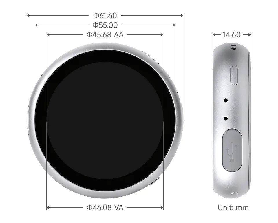
Dimensions
Factory Firmware Instructions
To help users quickly understand the various features of the product, we provide a factory test program that demonstrates the use of onboard screen, touch, audio, IMU, RTC, battery monitoring, TF card, and other functions. In addition to the ESP32-S3-Touch-LCD-1.85B main unit and the included cables, the following components are required to run all examples:
Required Components
- ESP32-S3-Touch-LCD-1.85B ×1
- USB Type-C cable ×1
- 3.7V Lithium Battery ×1 (optional, required for battery power and battery level measurement examples)
- TF card ×1 (optional, required for TF card and audio file playback examples)
- MP3 audio files should be placed in the
musicdirectory - AVI video files should be placed in the
videodirectory - JPG image files should be placed in the
photodirectory
- MP3 audio files should be placed in the
Firmware Download
- The factory firmware is located in the
Firmwaredirectory of the example repository. - The firmware file is named
ESP32-S3-Touch-LCD-1.85B-Factory.binand can be used to restore the factory demonstration program. - Use the Espressif Flash Download Tool to flash the firmware. The tool download link can be found in Resources and Documents.
USB Firmware Flashing Notes
If the port is not recognized or the board does not automatically enter download mode, manually enter Boot mode:
- Press and hold the BOOT button.
- Connect USB to the computer, or click download while already connected via USB.
- Release the BOOT button.
After programming, power cycle or reset the board to run the program.
App Example Introduction
An APP-style comprehensive application interface is shown using the Brookesia component, suitable for quickly verifying onboard LCD, touch, audio, voice, and peripheral functions.
- To exit an APP, swipe upward from the bottom of the screen.
- Swipe up from the bottom and hold in the middle of the screen to view recently running APPs; swiping up closes the APP process.
- In the XiaoZhi AI APP, long-press the BOOT button to return to the Brookesia interface.
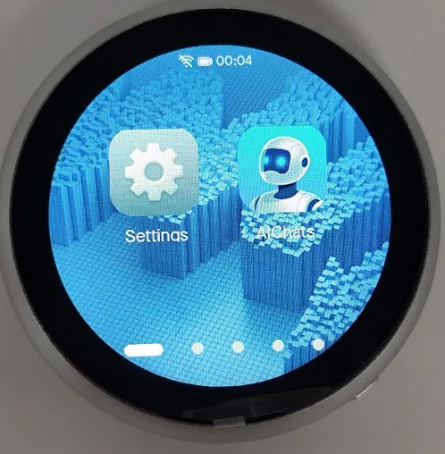
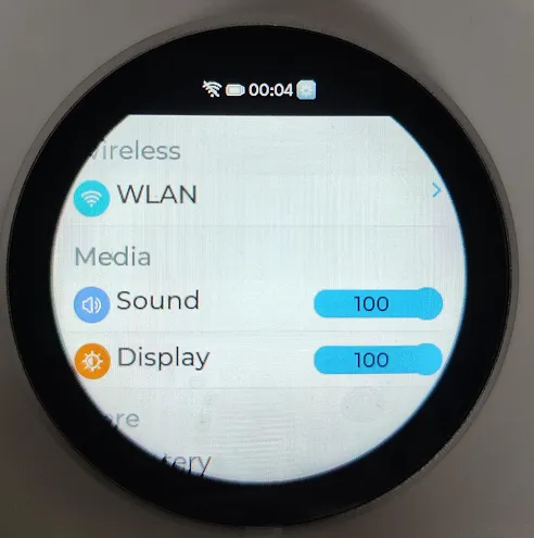
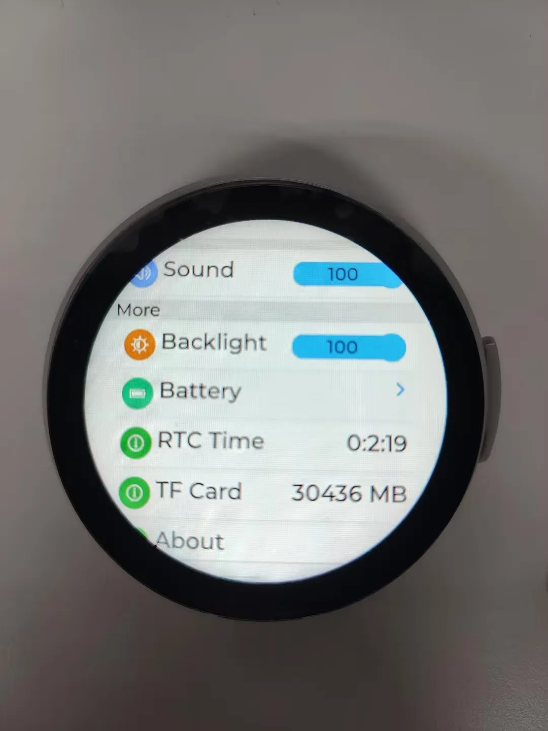
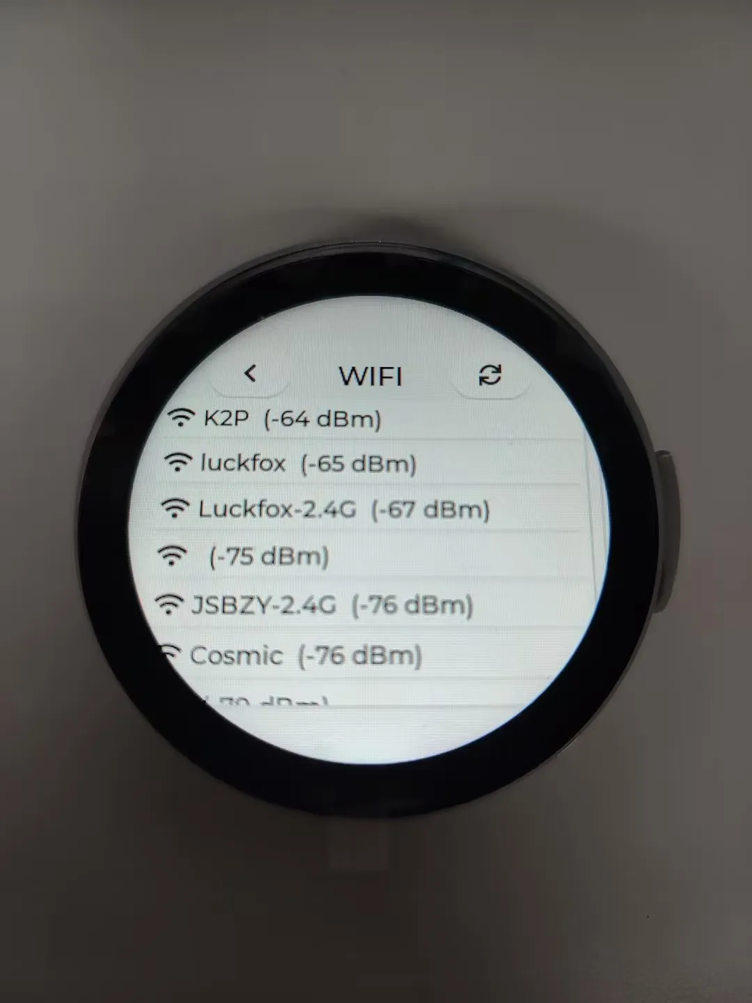
Settings App
- Supports Wi-Fi scanning and network configuration.
- Adjust screen brightness and volume.
- View battery status.
- View RTC time.
- View device information and MAC address, etc.
XiaoZhi APP
- Launches the native XiaoZhi application.
- Long-press the BOOT button to exit the XiaoZhi APP.
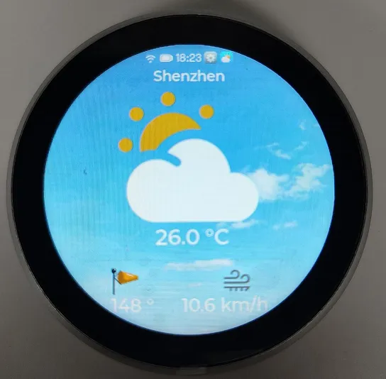
Weather APP
- Requires network connection and location.
- Displays the local weather interface.
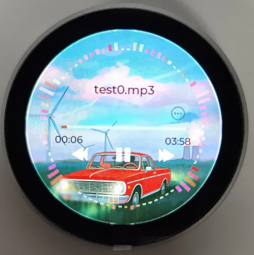
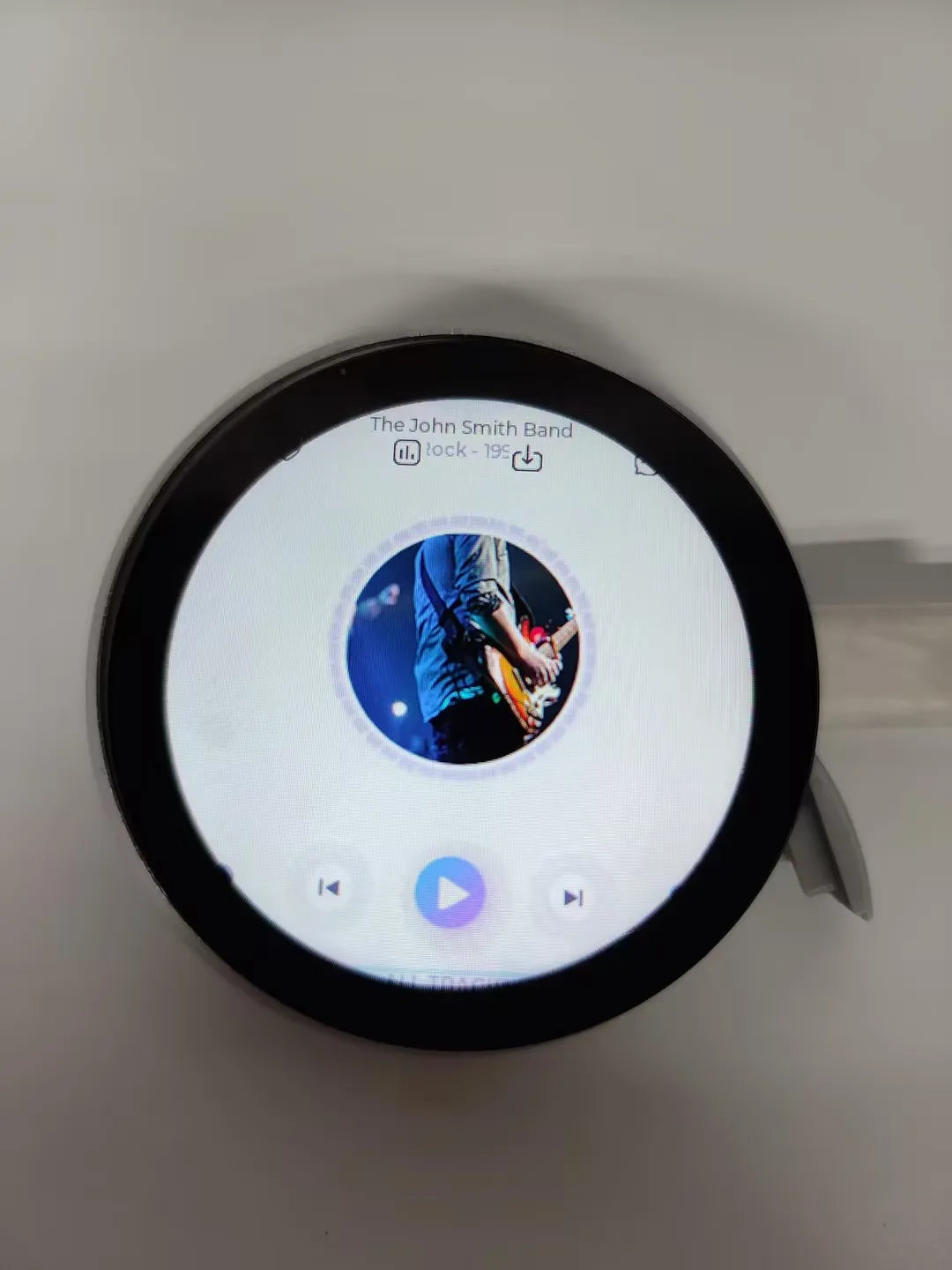
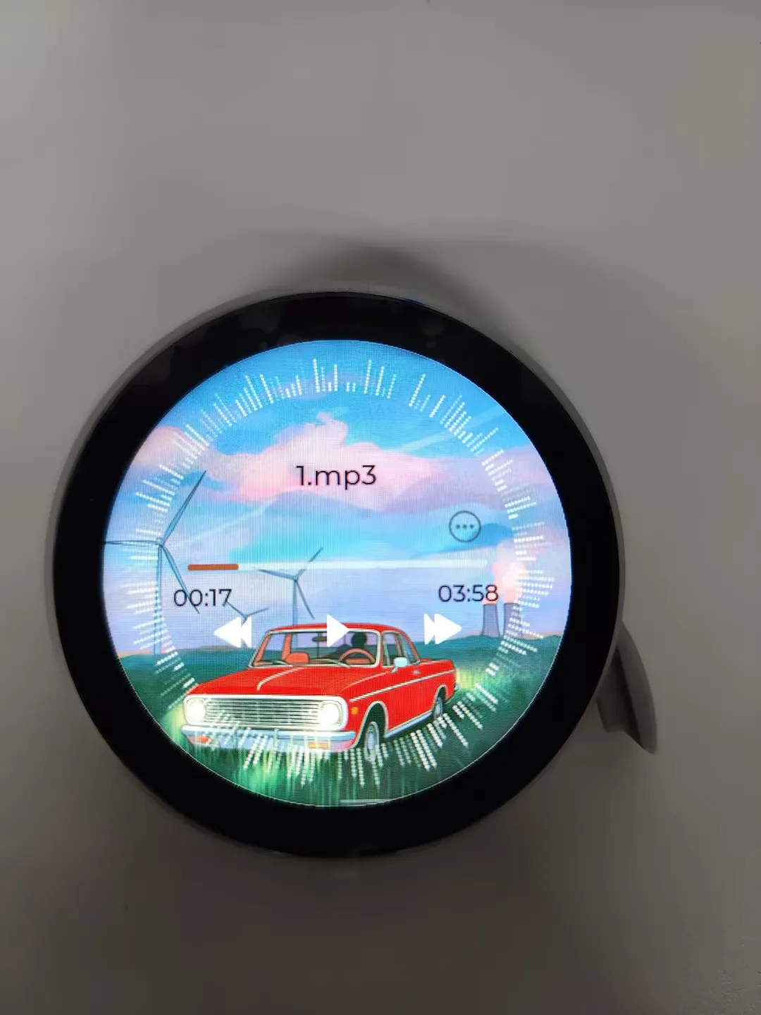
Music Player APP
- Simulates a music player interface.
- Requires a TF card with audio files placed as required for normal playback.
- Integrated FFT spectrum analysis display.
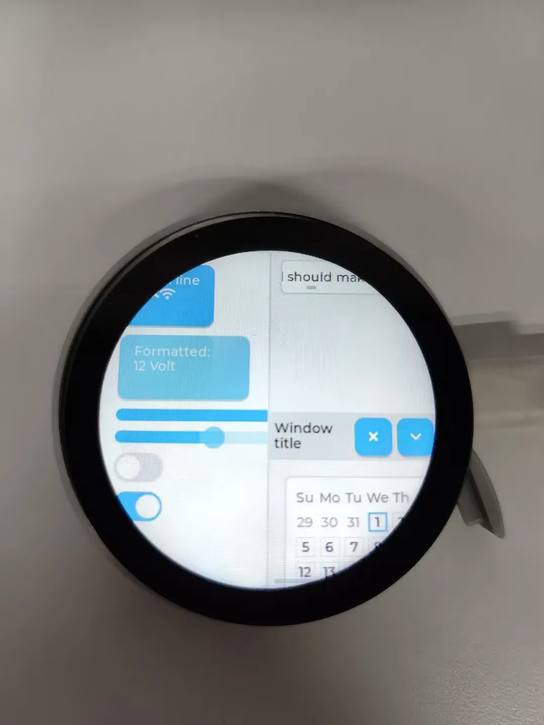
Squareline APP
- Displays the LVGL squareline editor interface.
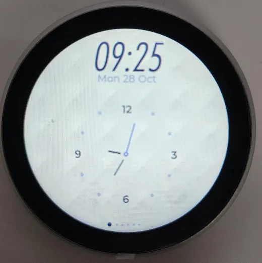
Photo Album APP
- Displays images from the TF card.
- Currently only supports JPG format; more formats will be supported in the future.
- Manual image zoom is required; currently only resolutions up to 360×360 are supported.
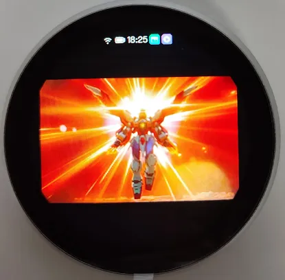
Video Player APP
- Plays AVI videos from the TF card.
- Currently only supports AVI videos with JPG encoding.
- Currently only supports resolutions up to 360×360; larger resolutions cannot be played.
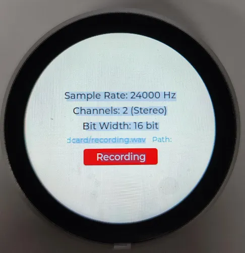
Recorder APP
- Used to test dual-microphone recording functionality.
- Recorded audio is saved to the TF card.
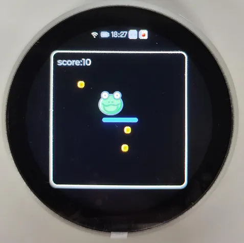
Chipmunk2d APP
- A small game combining the Chipmunk2d physics engine and gyroscope data.
- Before use, place the device flat to calibrate the gyroscope.
Working with Arduino
This chapter contains the following sections. Please read as needed:
Arduino Getting Started
New to Arduino ESP32 development and looking for a quick start? We have prepared a comprehensive Getting Started Tutorial for you.
- Section 0: Getting to Know ESP32
- Section 1: Installing and Configuring Arduino IDE
- Section 2: Arduino Basics
- Section 3: Digital Output/Input
- Section 4: Analog Input
- Section 5: Pulse Width Modulation (PWM)
- Section 6: Serial Communication (UART)
- Section 7: I2C Communication
- Section 8: SPI Communication
- Section 9: Wi-Fi Basics
- Section 10: Web Server
- Section 11: Bluetooth
- Section 12: LVGL GUI Development
- Section 13: Comprehensive Project
Note: This tutorial uses the ESP32-S3-Zero as a reference example, and all hardware code is based on its pinout. Before you start, we recommend checking the pinout of your development board to ensure the pin configuration is correct.
Setting Up the Development Environment
1. Installing and Configuring the Arduino IDE
Please refer to the tutorial Installing and Configuring Arduino IDE to download and install the Arduino IDE and add ESP32 support.
2. Installing Libraries
- When installing Arduino libraries, there are typically two methods: online installation and offline installation. If the library installation requires offline installation, you must use the provided library files.
- For most libraries, users can easily search for and install them via the Arduino IDE's online Library Manager. However, some open-source or custom libraries are not synchronized to the Arduino Library Manager and therefore cannot be found through online search. In this case, users can only install these libraries manually via offline methods.
- You can click this link to download the example package for the ESP32-S3-Touch-LCD-1.85B board from the
Arduinodirectory. TheArduino\librariesdirectory within this package contains all the necessary library files required for this tutorial.
| Library/File Name | Description | Version | Installation Method |
|---|---|---|---|
| ESP32-audioI2S-master | Audio playback library | v3.4.5 | Install via Library Manager or manually |
| SensorLib | PCF85063, QMI8658 sensor driver library | v0.3.1 | Install via library manager or manually |
| es7210 | ES7210 driver | - | Manual installation |
| es8311 | ES8311 driver | - | Manual installation |
| kode_bq27220 | bq27220 battery gauge driver | —— | Manual installation |
| lvgl | LVGL UI | v8.4.0 | Manual installation |
There are strong dependencies between versions of LVGL and its driver libraries. For example, a driver written for LVGL v8 may not be compatible with LVGL v9. To ensure that the examples can be reproduced reliably, it is recommended to use the specific versions listed in the table above. Mixing different versions of libraries may lead to compilation failures or runtime errors.
Installation Steps:
Navigate to the downloaded example package.
Copy all folders (Arduino_DriveBus, GFX_Library_for_Arduino, etc.) in the
Arduino\librariesdirectory to the Arduino library folder.INFOThe path to the Arduino libraries folder is typically:
c:\Users\<username>\Documents\Arduino\libraries.You can also locate it in the Arduino IDE by going to File > Preferences and checking the "Sketchbook location". The libraries folder is the
librariessubfolder within this path.For other installation methods, please refer to: Arduino Library Management Tutorial.
Board Installation Instructions for ESP32-S3-Touch-LCD-1.85B
| Board Name | Installation Requirement | Version Requirement |
|---|---|---|
| ESP32 by Espressif Systems | "Offline installation" / "Online installation" | ≥3.2.0 |
Example
The Arduino examples are located in the Arduino/examples directory of the example package.
| Example | Basic Program Description | Dependency Library |
|---|---|---|
| 01_lvgl_demo | Demonstrates basic LVGL graphics library functions, tests basic display performance | lvgl |
| 02_lvgl_BQ27220 | Tests the BQ27220 battery gauge sensor | kode_bq27220 |
| 03_audio_out_no_tf | Audio playback test | es8311 |
| 04_SDMMC_Test | TF card mounting and file read/write test | —— |
| 05_audio_out_tf | LVGL demonstration | LVGL, Arduino_DriveBus |
| 06_esp_sr | ES7210 driver example, voice detection | —— |
| 07_I2C_qmi8658 | Gyroscope driver test | SensorLib |
| 08_I2C_pcf85063 | RTC real-time clock driver test | SensorLib |
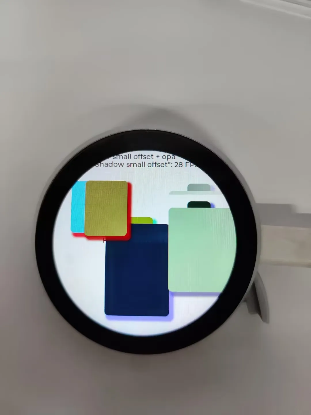
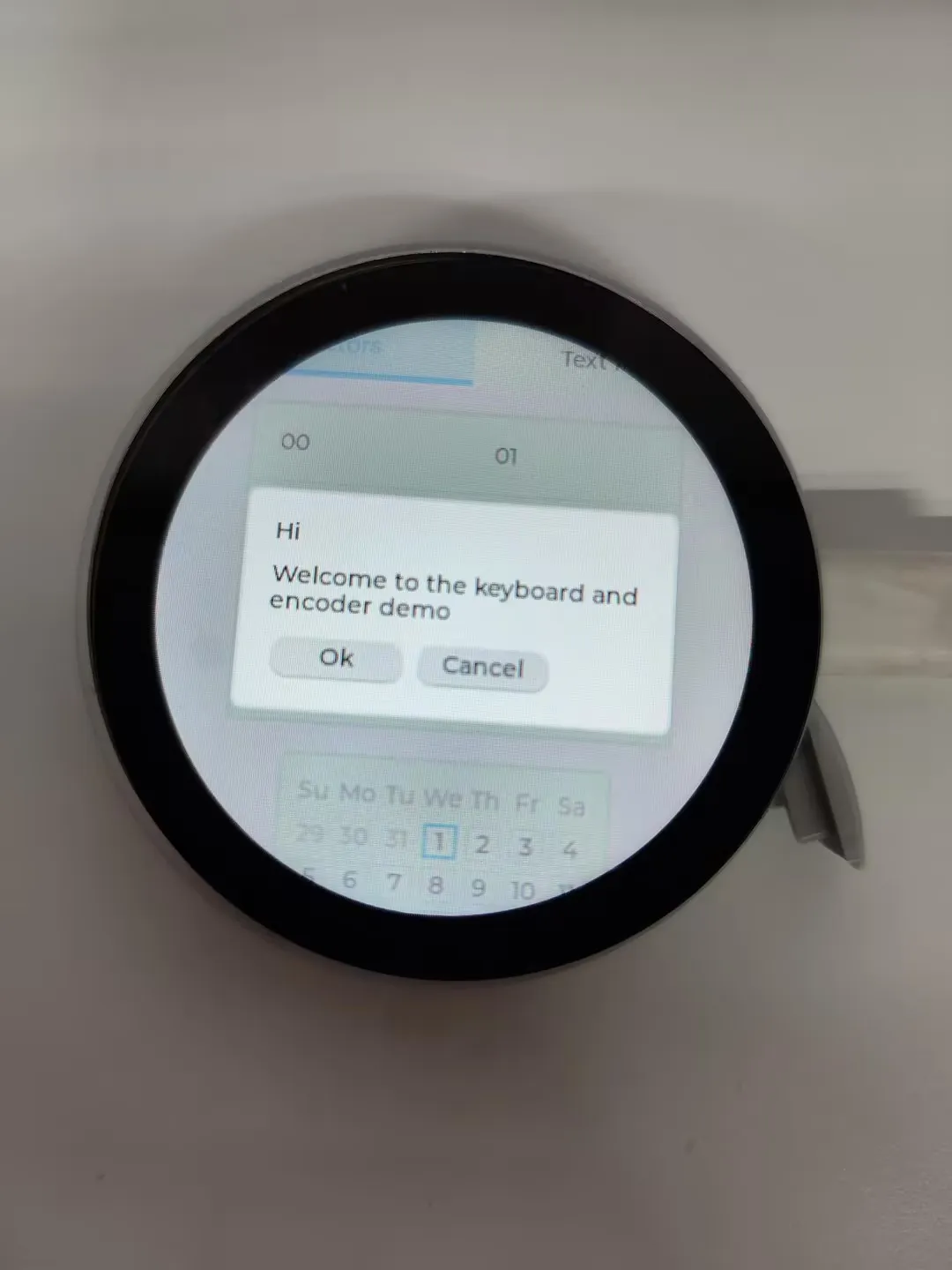
01_lvgl_demo
Example Description
- This example demonstrates how to drive the display using Arduino and run multiple LVGL example programs.
Hardware Connection
- Connect the development board to the computer.
Code Analysis
Initialize the screen, touch, and LVGL:
I2C_Init();Backlight_Init();LCD_Init();Lvgl_Init();Select the LVGL example to run:
lv_demo_widgets();// lv_demo_benchmark();// lv_demo_keypad_encoder();// lv_demo_music();// lv_demo_stress();
Operation Result
  |
|---|
  |
|---|
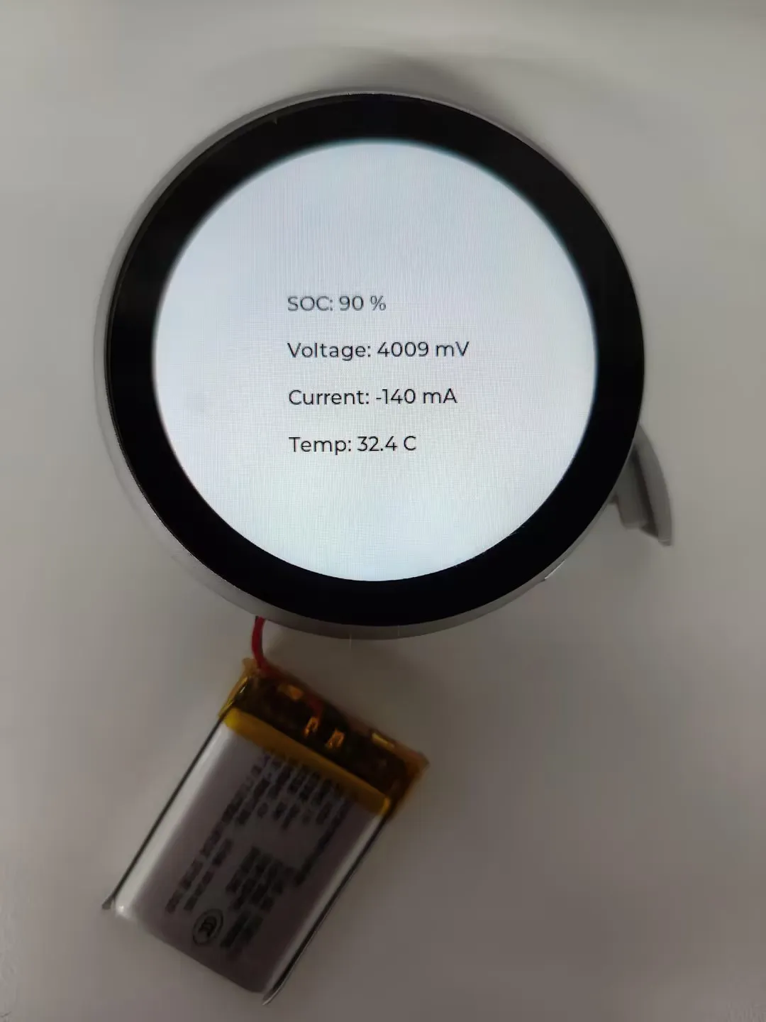
02_lvgl_BQ27220
Example Description
- This example demonstrates using the BQ27220 battery gauge sensor to read battery information and display it in LVGL.
Hardware Connection
- Connect a 3.7V lithium battery.
Code Analysis
Create an I2C mutex to prevent conflicts between touch and BQ27220 readings in different tasks.
wire_mutex = xSemaphoreCreateMutex();Initialize BQ27220:
if (!gauge.begin(Wire, 0x55, I2C_SDA_PIN, I2C_SCL_PIN, 400000)) {Serial.println("BQ27220 not found");while (1) delay(1000);}
Operation Result
03_audio_out_no_tf
Example Description
- This example demonstrates playing music using the ES8311 audio DAC
Hardware Connection
- Connect a speaker
- Connect the development board to the computer.
Code Analysis
Initialize the I2C controller and external I/O expander:
DEV_I2C_Init();IO_EXTENSION_Init();IO_EXTENSION_Output(IO_EXTENSION_IO_6, 1);Initialize ES8311:
es8311_codec_init();Initialize I2S and enable the power amplifier (PA) pin:
setupI2S();IO_EXTENSION_Output(IO_EXTENSION_IO_4, 1);In the loop, continuously write data to the ES8311 via I2S:
void loop() {i2s.write((uint8_t *)audio_data, AUDIO_SAMPLES * 2);}
Operation Result
- The screen has no display.
- After flashing the program, music will start playing automatically
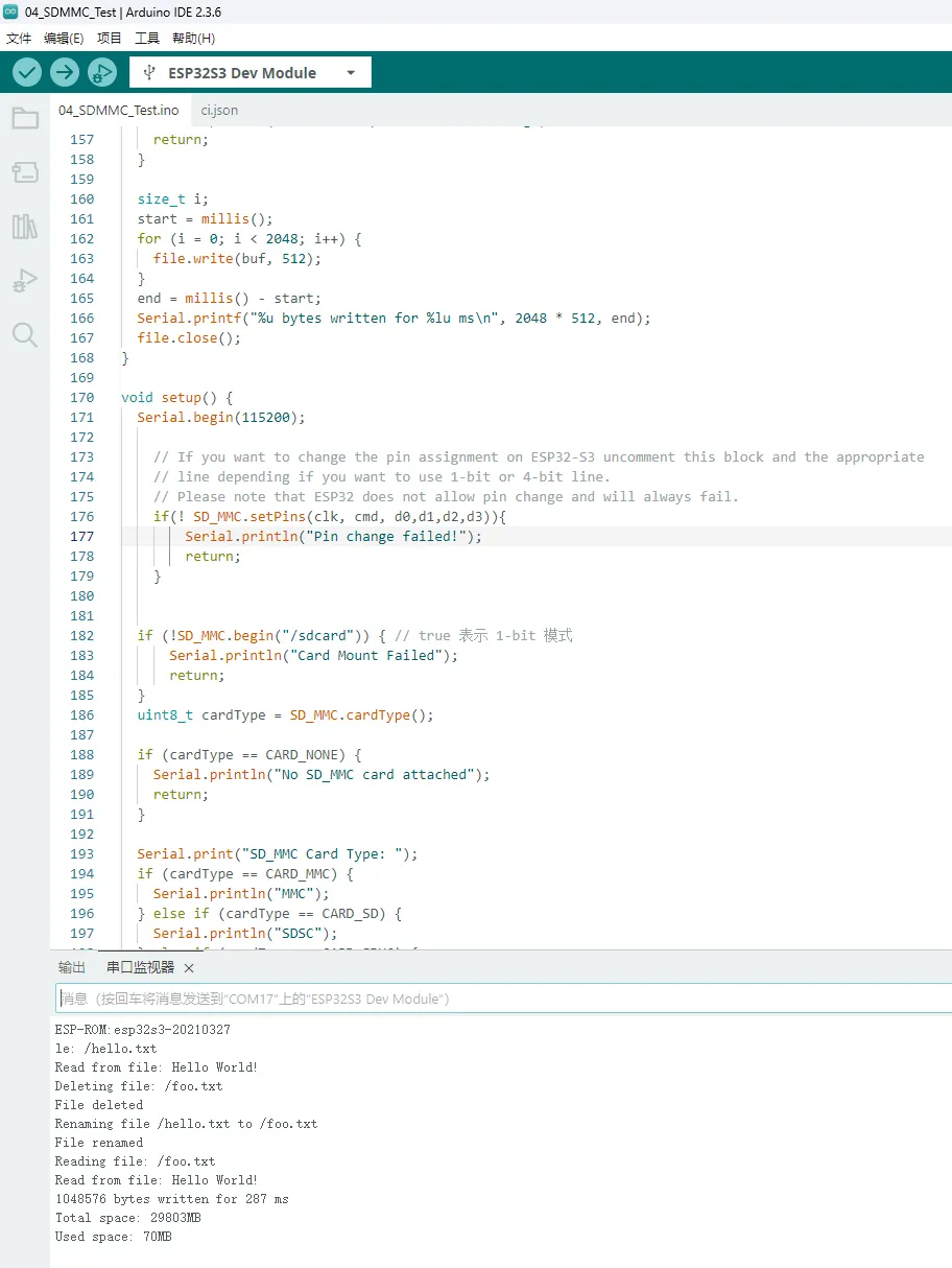
04_SDMMC_Test
Example Description
- This example demonstrates how to mount a TF card and test file reading and writing
Hardware Connection
- Insert a TF card
- Connect the development board to the computer.
Code Analysis
Set the SDIO interface pins and mount the file system:
if(!SD_MMC.setPins(clk, cmd, d0)){Serial.println("Pin change failed!");return;}if (!SD_MMC.begin( "/sdcard", true)) {Serial.println("Card Mount Failed");return;}File read/write test:
listDir(SD_MMC, "/", 0);createDir(SD_MMC, "/mydir");listDir(SD_MMC, "/", 0);removeDir(SD_MMC, "/mydir");listDir(SD_MMC, "/", 2);writeFile(SD_MMC, "/hello.txt", "Hello ");appendFile(SD_MMC, "/hello.txt", "World!\n");readFile(SD_MMC, "/hello.txt");deleteFile(SD_MMC, "/foo.txt");renameFile(SD_MMC, "/hello.txt", "/foo.txt");readFile(SD_MMC, "/foo.txt");testFileIO(SD_MMC, "/test.txt");Serial.printf("Total space: %lluMB\n", SD_MMC.totalBytes() / (1024 * 1024));Serial.printf("Used space: %lluMB\n", SD_MMC.usedBytes() / (1024 * 1024));
Operation Result
05_audio_out_tf
Example Description
- This example demonstrates playing MP3 audio from a TF card
Hardware Connection
- Insert a TF card with an audio file named ff-16b-1c-44100hz.mp3 in the root directory
- Connect a speaker
- Connect the development board to the computer.
Code Analysis
Initialize I2S and the audio decoder library, and set the playback path:
audio.setPinout(I2S_BCK_PIN, I2S_LRCK_PIN, I2S_DOUT_PIN,I2S_MCLK_PIN);audio.connecttoFS(SD_MMC, "ff-16b-1c-44100hz.mp3");
Operation Result
- The screen has no display.
- After flashing the program, MP3 music will start playing automatically.
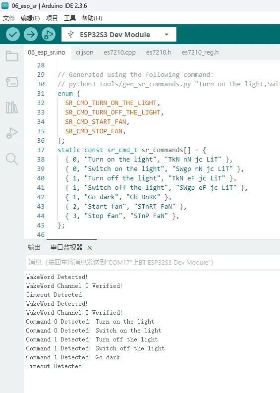
06_esp_sr
Example Description
- This example demonstrates using the ES7210 audio ADC chip for voice wake-up and speech recognition
Hardware Connection
- Connect the development board to the computer.
Code Analysis
Initialize I2S and the ES7210 audio ADC:
Wire.begin(I2C_PIN_SDA, I2C_PIN_SCL);es7210_init();i2s.setPins(I2S_PIN_BCK, I2S_PIN_WS, I2S_PIN_DOUT, I2S_PIN_DIN, I2S_PIN_MCK);i2s.setTimeout(1000);i2s.begin(I2S_MODE_STD, 16000, I2S_DATA_BIT_WIDTH_16BIT, I2S_SLOT_MODE_STEREO);Register callbacks for voice wake-up and speech recognition events, then start ESP-SR:
ESP_SR.onEvent(onSrEvent);ESP_SR.begin(i2s, sr_commands, sizeof(sr_commands) / sizeof(sr_cmd_t), SR_CHANNELS_STEREO, SR_MODE_WAKEWORD);
Operation Result
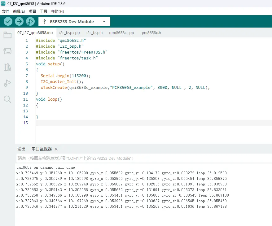
07_I2C_qmi8658
Example Description
- Initialize the QMI8658 chip via the I2C protocol, then read the corresponding attitude information every 200ms and print it to the terminal.
Hardware Connection
- Connect the board to the computer using a USB cable.
Code Analysis
void i2c_qmi_loop_task(void *arg): Creates a QMI task to acquire attitude information. The task reads and prints accelerometer and gyroscope data at 200ms intervals, and outputs the results to the serial console.
Operation Result
- Open the Serial Monitor to see the printed raw data from the IMU (Euler angles need to be converted by yourself), as shown in the figure below:
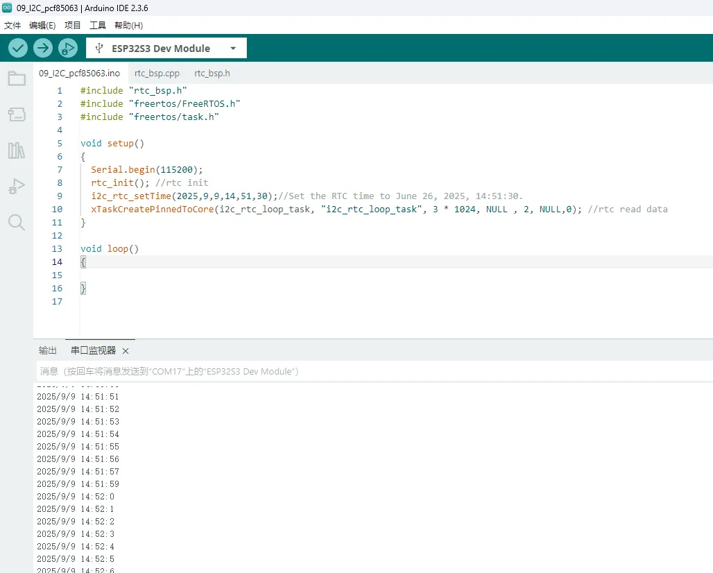
08_I2C_pcf85063
Example Description
- Through the I2C protocol, initialize the PCF85063 chip, set the time, and then periodically read the time and print it to the terminal
Hardware Connection
- Connect the board to the computer using a USB cable.
Code Analysis
void i2c_rtc_loop_task(void *arg): Creates an RTC task to implement the RTC function, reading the clock of the RTC chip every second and outputting it to the terminal.
Operation Result
- After the program is compiled and downloaded, open the serial port monitoring to see the RTC time of the printout, as shown in the following figure:
ESP-IDF
This chapter contains the following sections. Please read as needed:
ESP-IDF Getting Started
New to ESP32 ESP-IDF development and looking to get started quickly? We have prepared a general Getting Started Tutorial for you.
- Section 1: Environment Setup
- Section 2: Running Examples
- Section 3: Creating a Project
- Section 4: Using Components
- Section 5: Debugging
- Section 6: FreeRTOS
- Section 7: Peripherals
- Section 8: Wi-Fi Programming
- Section 9: BLE Programming
Please Note: This tutorial uses the ESP32-S3-Zero as a teaching example, and all hardware code is based on its pinout. Before you start, it is recommended that you check the pinout of your development board to ensure the pin configuration is correct.
Setting Up the Development Environment
For the ESP32-S3-Touch-LCD-1.85B development board, ESP-IDF V5.5.3 or above is required.
The following guide uses Windows as an example, demonstrating development using VS Code + the ESP-IDF extension. macOS and Linux users should refer to the official documentation.
The screenshots in this section use ESP-IDF V5.5.2 as an example. When installing, please select the ESP-IDF version that matches your board's example.
Install the ESP-IDF Development Environment
Download the installation manager from the ESP-IDF Installation Manager page. This is Espressif's latest cross-platform installer. The following steps demonstrate how to use its offline installation feature.
Click the Offline Installer tab on the page, then select Windows as the operating system and the ESP-IDF version you need (the version shown in the screenshot is for reference only — choose the version that fits your actual needs).
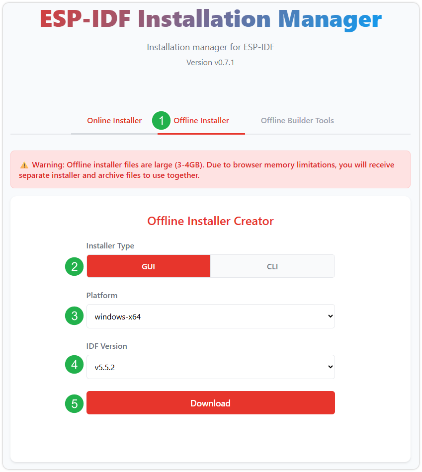
After confirming your selection, click the download button. The browser will automatically download two files: the ESP-IDF Offline Package (.zst) and the ESP-IDF Installer (.exe).
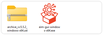
Please wait for both files to finish downloading.
Once the download is complete, double-click to run the ESP-IDF Installer (eim-gui-windows-x64.exe).
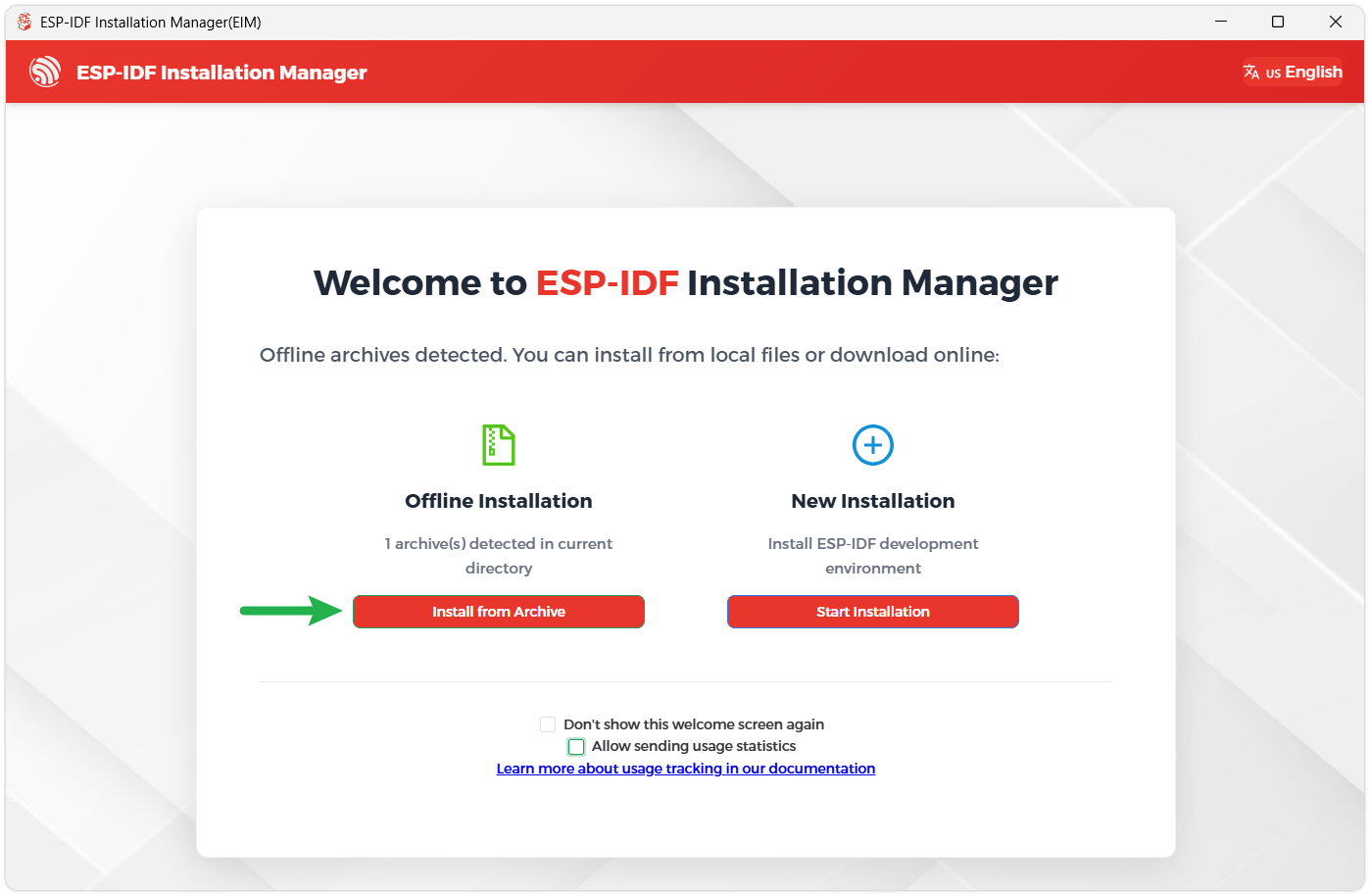
The installer will automatically detect if the offline package exists in the same directory. Click Install from archive.
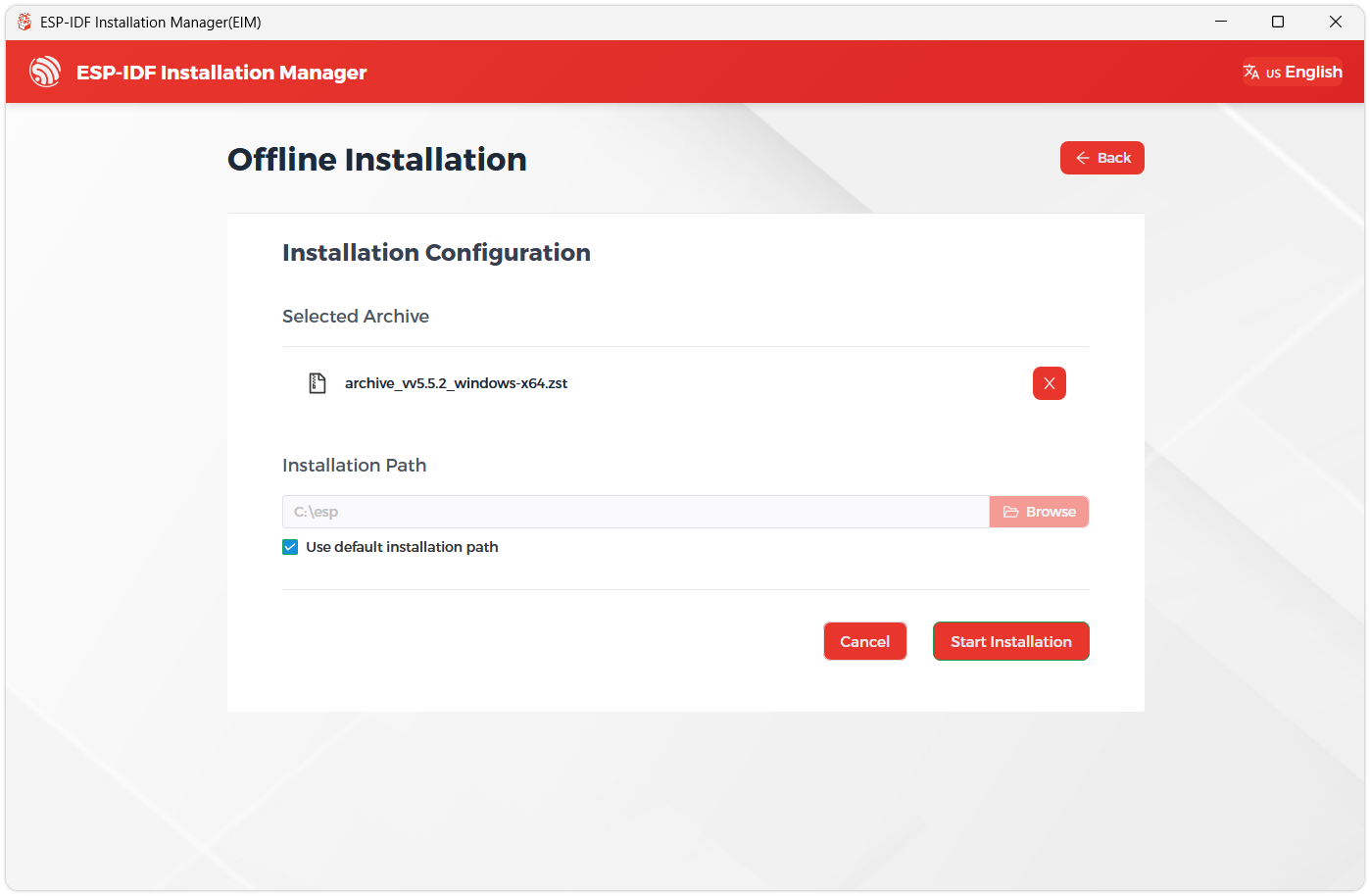
Next, select the installation path. We recommend using the default path. If you need to customize it, ensure the path does not contain Chinese characters or spaces. Click Start installation to proceed.
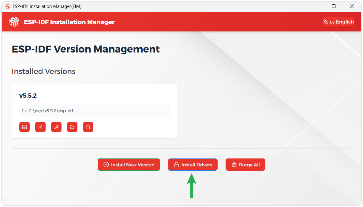
When you see the following screen, the ESP-IDF installation is successful.
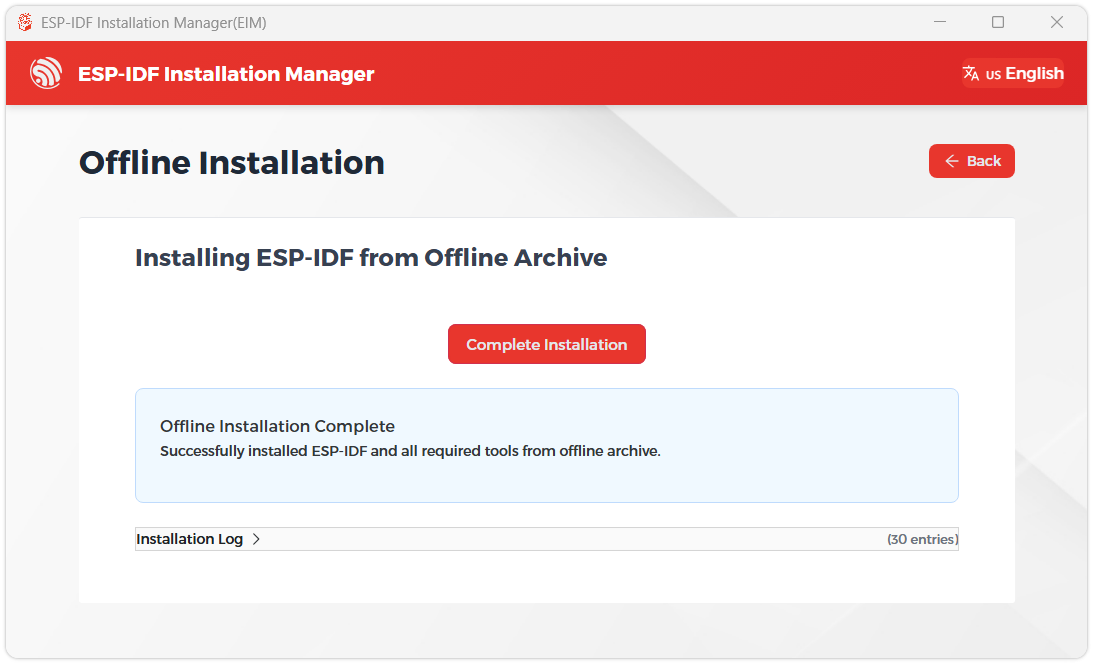
We recommend installing the drivers as well. Click Finish installation, then select Install driver.
Install Visual Studio Code and the ESP-IDF Extension
Download and install Visual Studio Code.
During installation, it is recommended to check Add "Open with Code" action to Windows Explorer file context menu to facilitate opening project folders quickly.
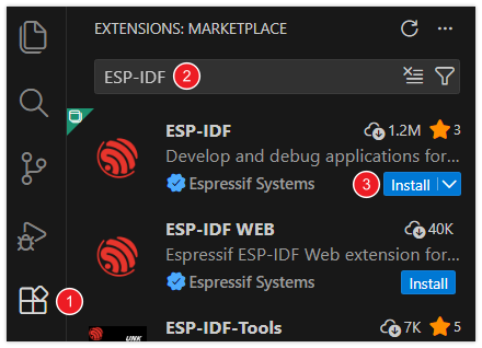
In VS Code, click the Extensions icon
 in the Activity Bar on the side (or use the shortcut Ctrl + Shift + X) to open the Extensions view.
Enter ESP-IDF in the search box, locate the ESP-IDF extension, and click Install.
For ESP-IDF extension versions ≥ 2.0, the extension will automatically detect and recognize the ESP-IDF environment installed in the previous steps, requiring no manual configuration.
Example
The ESP-IDF examples are located in the ESP-IDF directory of the example package.
| Example | Basic Description |
|---|---|
| 01_comprehensive_example | Comprehensive example program driving LCD, audio, and onboard sensors |
| 02_lvgl_demo | Display LVGL demo |
| 03_mp3_player | Scan the TF card and play MP3 |
| 04_esp_wakeword_det | Use the esp-sr component to implement voice wake-up and command word recognition |
| 05_esp-brookesia | Display an LVGL APP-style UI using the brookesia component |
| 06_qmi8658_test | Test the gyroscope |
| 07_pcf85063_test | Test the RTC real-time clock |
| 08_bq27220_test | Test the onboard battery monitoring IC |
01_comprehensive_example
Example Description
- This is a comprehensive example program demonstrating LCD touch screen driving, LVGL initialization, audio driving, and various onboard peripherals.
Hardware Connection
- Insert a 3.7V Li-ion battery or connect the development board to a computer. A TF card is required (create a
musicfolder in the root directory to store MP3 files).
Code Analysis
Initialize the screen, touch, backlight, LVGL, and TF card:
lv_display_t *disp = bsp_display_start();lv_indev_t *tp = bsp_display_get_input_dev();bsp_display_backlight_on();bsp_sdcard_mount();Initialize the audio player, onboard sensors, and wake-word detection task:
Audio_Play_Init();msg_driver_init();wake_word_drv_init();Scan for MP3 files in the
musicfolder:esp_err_t err = get_file_list_by_ext("/sdcard/music",".mp3",&mp3_files);if (err == ESP_OK) {for (int i = 0; i < mp3_files.count; i++) {printf("MP3[%d]: %s\n", i, mp3_files.list[i]);}}Create the UI:
bsp_display_lock(-1);main_screen = lv_obj_create(NULL);lv_obj_t * tv = lv_tileview_create(main_screen);lv_obj_t * tile1 = lv_tileview_add_tile(tv, 0, 0, LV_DIR_RIGHT);msg_ui_screen_init(main_screen,tile1);lv_obj_t * tile2 = lv_tileview_add_tile(tv, 1, 0, LV_DIR_LEFT | LV_DIR_RIGHT);init_music_ui_screen(tile2,&mp3_files);lv_obj_t * tile3 = lv_tileview_add_tile(tv, 2, 0, LV_DIR_LEFT);eaf_ui_screen_init(tile3);lv_screen_load(main_screen);bsp_display_unlock();Test voice wake-up and command word instructions::
// Wake wordHi,ESP// CommandsTurn on the backlightTurn off the backlightBacklight is brightestBacklight is darkest
Operation Result
- Three screens are displayed using LVGL's tileview; swipe left/right to switch.
  |
|---|
    |
|---|
02_lvgl_demo
Example Description
- This example shows the official LVGL example.
Hardware Connection
- Connect the development board to the computer.
Code Analysis
Load the LVGL demo:
bsp_display_lock(-1);lv_demo_widgets();bsp_display_unlock();
Operation Result
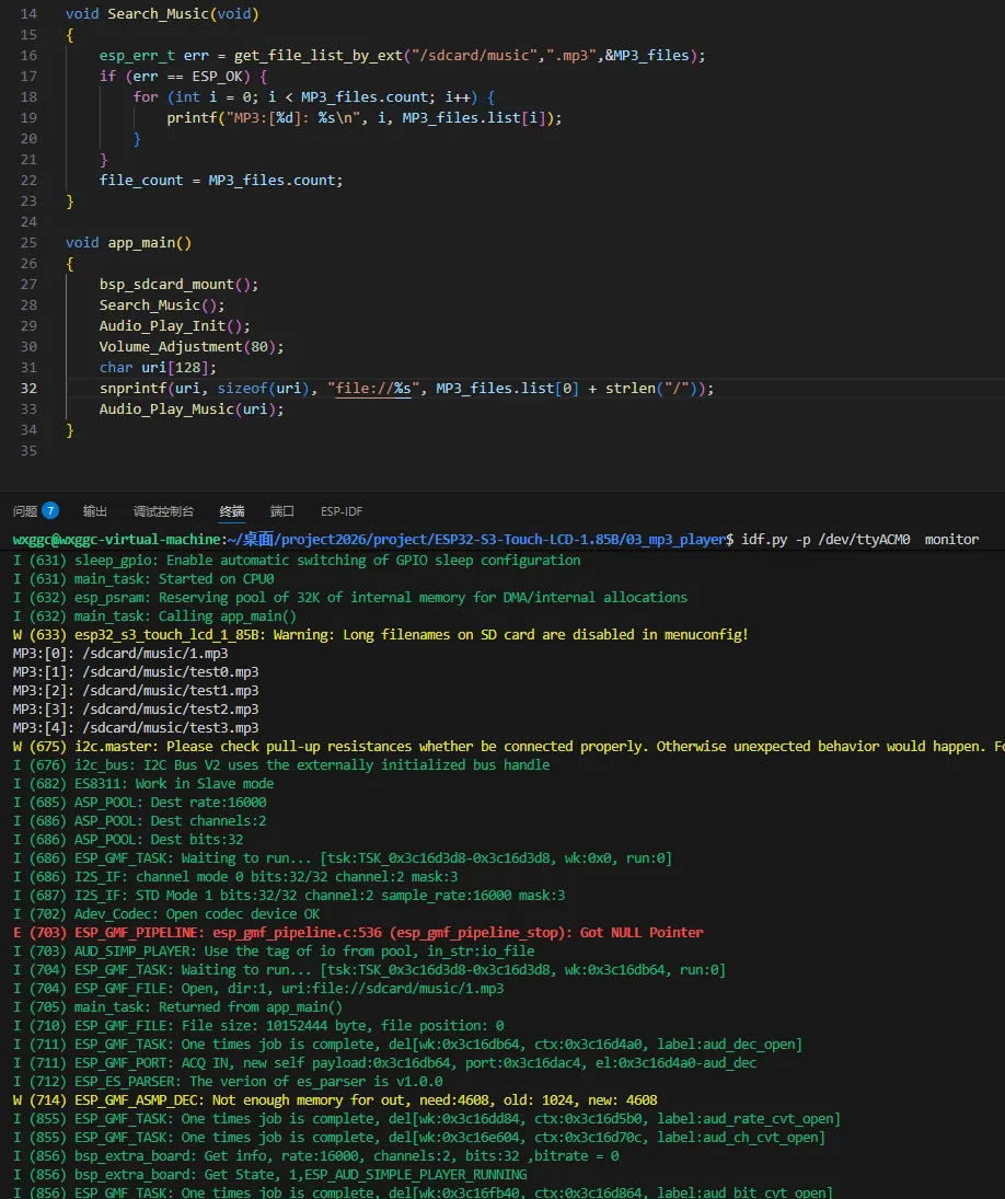
03_mp3_player
Example Description
- This example tests TF card initialization, scanning for MP3 files, and playing them.
Hardware Connection
- Connect the development board to the computer. A TF card is required (create a
musicfolder in the root directory to store MP3 files).
Code Analysis
Scan for MP3 files and save the file names:
void Search_Music(void){esp_err_t err = get_file_list_by_ext("/sdcard/music",".mp3",&MP3_files);if (err == ESP_OK) {for (int i = 0; i < MP3_files.count; i++) {printf("MP3:[%d]: %s\n", i, MP3_files.list[i]);}}file_count = MP3_files.count;}
Operation Result
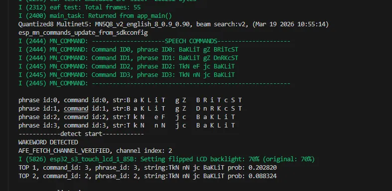
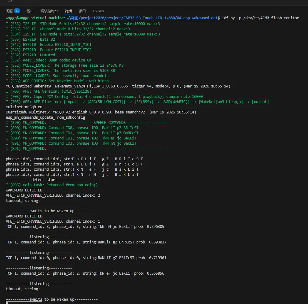
04_esp_wakeword_det
Example Description
- This example demonstrates offline voice wake-up and speech recognition using the ESP-SR component
Hardware Connection
- Connect the development board to the computer.
- Do not block the microphone
Code Analysis
Initialize the microphone and obtain a handle:
record_dev = bsp_audio_codec_microphone_init();esp_codec_dev_sample_info_t fs = {.bits_per_sample = 32,.channel = 2,.sample_rate = 16000,};esp_codec_dev_set_in_gain(record_dev, 30.0);esp_codec_dev_open(record_dev, &fs);Initialize the voice model:
models = esp_srmodel_init("model"); // partition label defined in partitions.csvafe_config_t *afe_config = afe_config_init(bsp_get_input_format(), models, AFE_TYPE_SR, AFE_MODE_LOW_COST);afe_handle = esp_afe_handle_from_config(afe_config);esp_afe_sr_data_t *afe_data = afe_handle->create_from_config(afe_config);afe_config_free(afe_config);xTaskCreatePinnedToCore(&detect_Task, "detect", 8 * 1024, (void*)afe_data, 5, NULL, 0);xTaskCreatePinnedToCore(&feed_Task, "feed", 8 * 1024, (void*)afe_data, 5, NULL, 1);
Operation Result
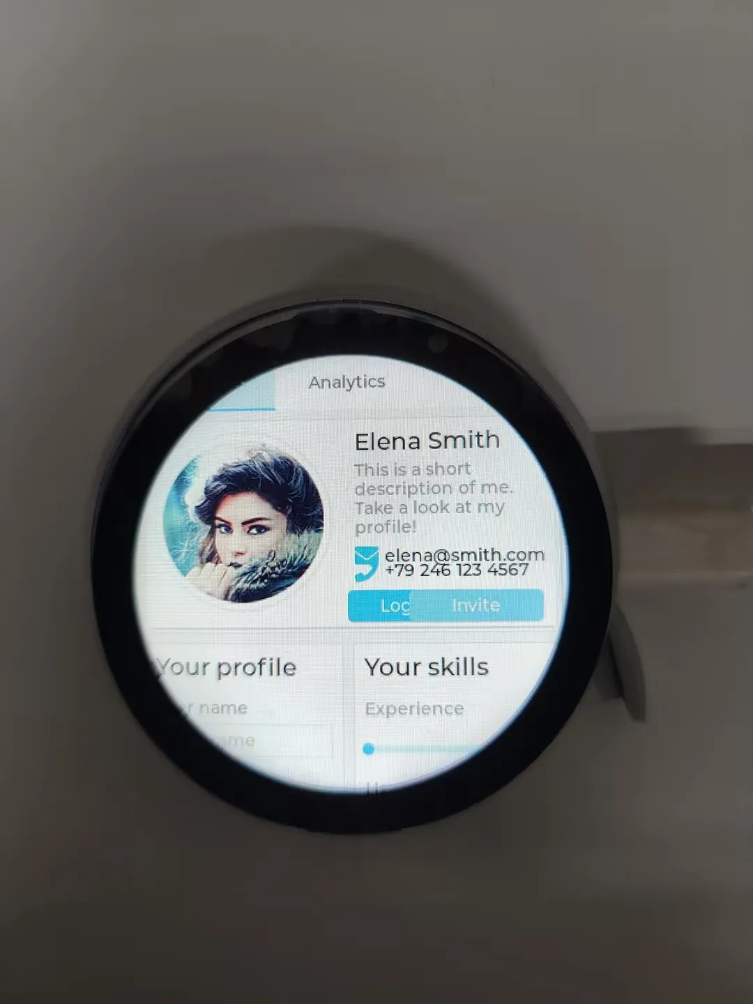
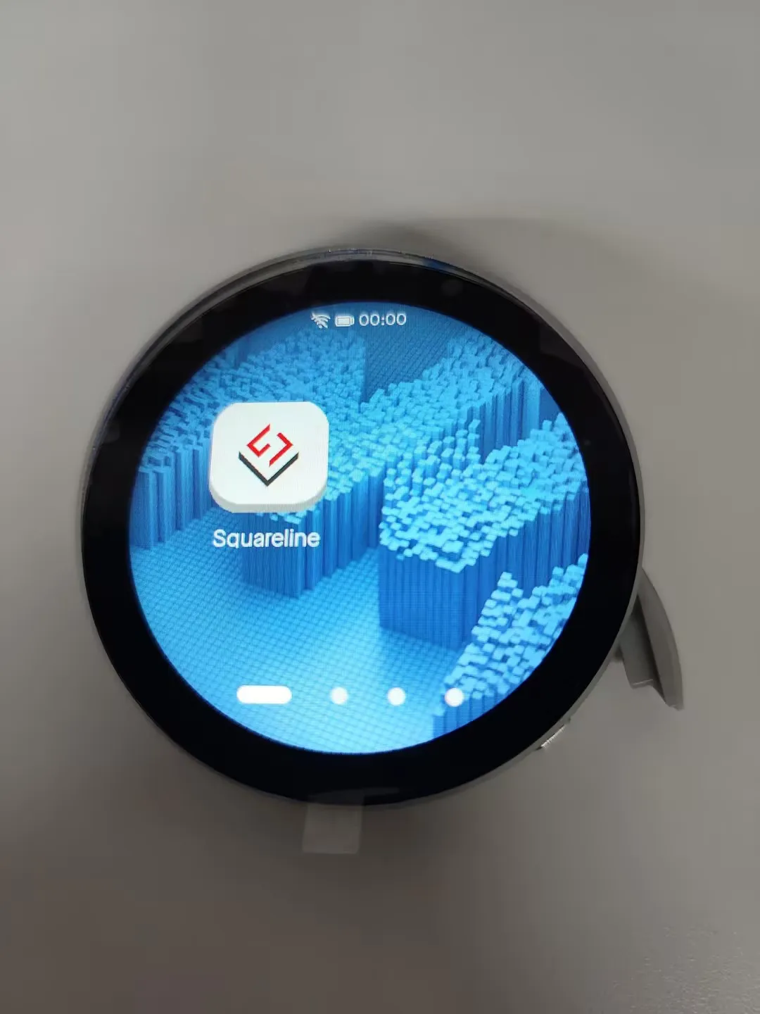
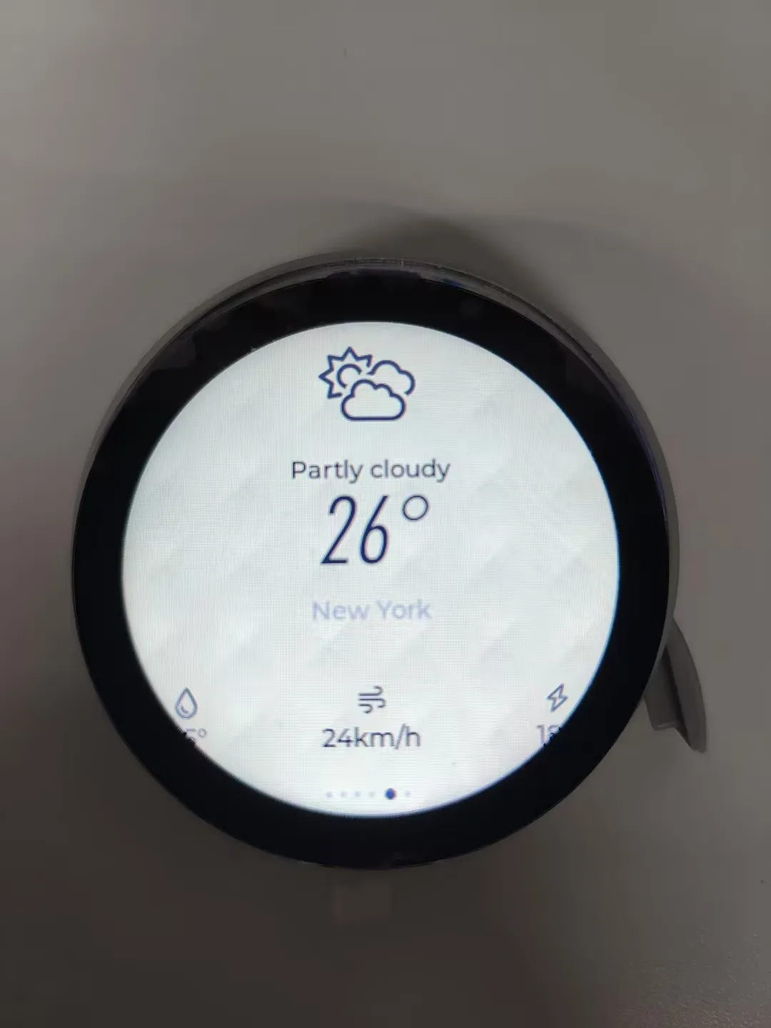
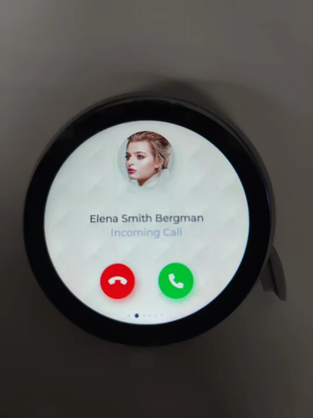
05_esp-brookesia
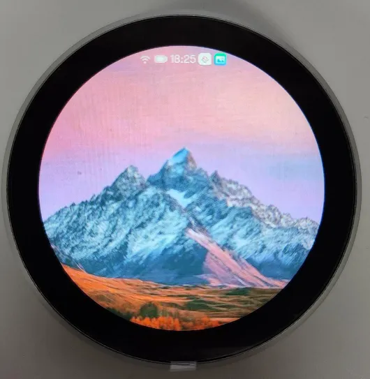
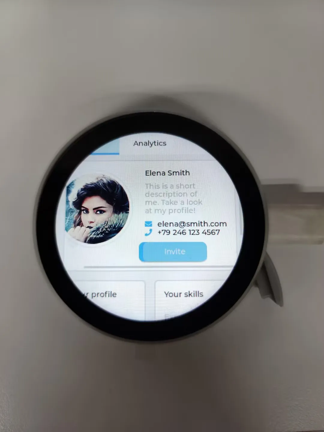
Example Description
- This example demonstrates a complete phone-style UI system, including components such as a status bar, navigation bar, app launcher, and gesture interaction
Hardware Connection
- Connect the development board to the computer.
Code Analysis
Initialize the phone UI:
ESP_LOGI(TAG, "Create phone object");systems::phone::Phone *phone = new systems::phone::Phone(disp);phone->setTouchDevice(tp);Stylesheet *stylesheet = new systems::phone::Stylesheet(STYLESHEET_360_360_DARK);ESP_UTILS_CHECK_NULL_EXIT(stylesheet, "Create stylesheet failed");ESP_UTILS_LOGI("Using stylesheet (%s)", stylesheet->core.name);ESP_UTILS_CHECK_FALSE_EXIT(phone->addStylesheet(stylesheet), "Add stylesheet failed");ESP_UTILS_CHECK_FALSE_EXIT(phone->activateStylesheet(stylesheet), "Activate stylesheet failed");delete stylesheet;Install the SquarelineDemo app:
auto app3 = esp_brookesia::apps::SquarelineDemo::requestInstance();ESP_UTILS_CHECK_FALSE_EXIT(phone->installApp(app3),"start Drawpanel failed");
Operation Result
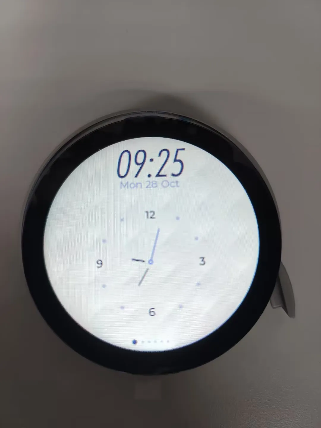  |
|---|
  |
|---|
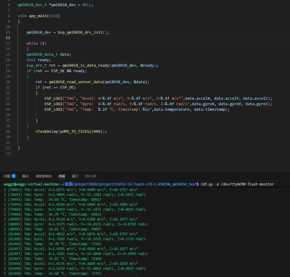
06_qmi8658_test
Example Description
- This example tests the QMI8658 gyroscope driver.
Hardware Connection
- Connect the development board to the computer.
Code Analysis
Initialize the QMI8658 and read data in a loop:
void app_main(void){qmi8658_dev = bsp_qmi8658_drv_init();while (1){qmi8658_data_t data;bool ready;esp_err_t ret = qmi8658_is_data_ready(qmi8658_dev, &ready);if (ret == ESP_OK && ready){ret = qmi8658_read_sensor_data(qmi8658_dev, &data);if (ret == ESP_OK){ESP_LOGI("TAG", "Accel: X=%.4f m/s², Y=%.4f m/s², Z=%.4f m/s²",data.accelX, data.accelY, data.accelZ);ESP_LOGI("TAG", "Gyro: X=%.4f rad/s, Y=%.4f rad/s, Z=%.4f rad/s",data.gyroX, data.gyroY, data.gyroZ);ESP_LOGI("TAG", "Temp: %.2f °C, Timestamp: %lu",data.temperature, data.timestamp);}}vTaskDelay(pdMS_TO_TICKS(1000));}}
Operation Result
Open the serial monitor
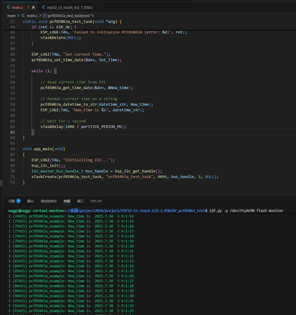
07_pcf85063_test
Example Description
- This example tests the RTC real-time clock.
Hardware Connection
- Connect the development board to the computer.
- Insert a 3.7V Li-ion battery (without a battery, RTC data cannot be read).
Code Analysis
Initialize the PCF85063A and set the time:
esp_err_t ret = pcf85063a_init(&dev, bus_handle, PCF85063A_ADDRESS);if (ret != ESP_OK) {ESP_LOGE(TAG, "Failed to initialize PCF85063A (error: %d)", ret);vTaskDelete(NULL);}ESP_LOGI(TAG, "Set current time.");pcf85063a_set_time_date(&dev, Set_Time);
Operation Result
Open the serial monitor
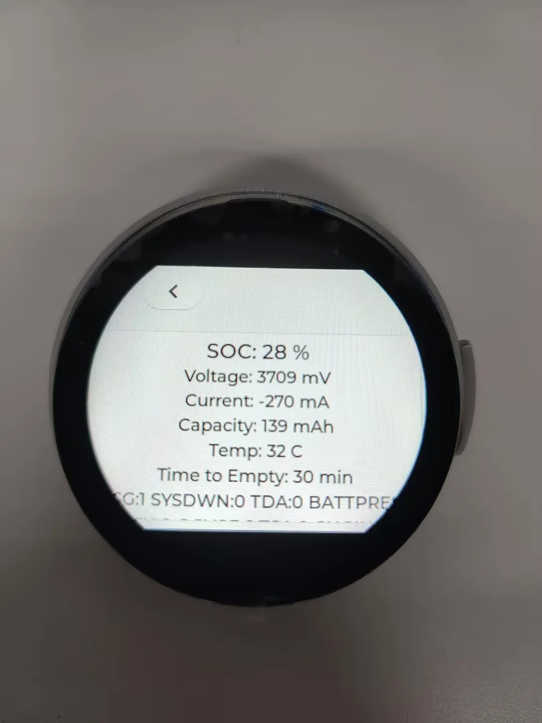
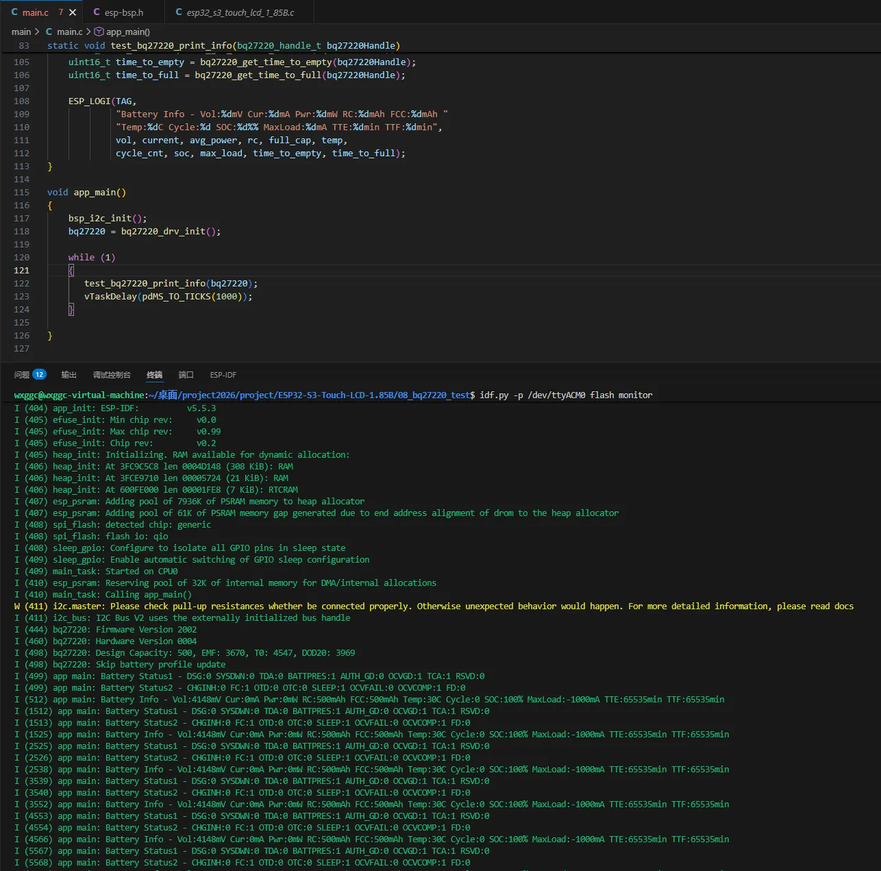
08_bq27220_test
Example Description
- This example tests the battery fuel gauge chip.
Hardware Connection
- Insert a 3.7V Li-ion battery (without a battery, battery data cannot be read).
Code Analysis
Initialize the BQ27220:
bq27220_handle_t bq27220_drv_init(void){i2c_bus = bsp_i2c_bus_get_handle();bq27220_config_t bq27220_cfg = {.i2c_bus = i2c_bus,.cfg = &default_config,.cedv = &default_cedv,};bq27220 = bq27220_create(&bq27220_cfg);if (!bq27220) {ESP_LOGE(TAG, "bq27220 create failed");}return bq27220;}Print battery-related information:
static void test_bq27220_print_info(bq27220_handle_t bq27220Handle){battery_status_t status = {};bq27220_get_battery_status(bq27220Handle, &status);ESP_LOGI(TAG, "Battery Status1 - DSG:%d SYSDWN:%d TDA:%d BATTPRES:%d AUTH_GD:%d OCVGD:%d TCA:%d RSVD:%d",status.DSG, status.SYSDWN, status.TDA, status.BATTPRES,status.AUTH_GD, status.OCVGD, status.TCA, status.RSVD);ESP_LOGI(TAG, "Battery Status2 - CHGINH:%d FC:%d OTD:%d OTC:%d SLEEP:%d OCVFAIL:%d OCVCOMP:%d FD:%d",status.CHGINH, status.FC, status.OTD, status.OTC,status.SLEEP, status.OCVFAIL, status.OCVCOMP, status.FD);uint16_t vol = bq27220_get_voltage(bq27220Handle);int16_t current = bq27220_get_current(bq27220Handle);uint16_t rc = bq27220_get_remaining_capacity(bq27220Handle);uint16_t full_cap = bq27220_get_full_charge_capacity(bq27220Handle);uint16_t temp = bq27220_get_temperature(bq27220Handle) / 10 - 273;uint16_t cycle_cnt = bq27220_get_cycle_count(bq27220Handle);uint16_t soc = bq27220_get_state_of_charge(bq27220Handle);int16_t avg_power = bq27220_get_average_power(bq27220Handle);int16_t max_load = bq27220_get_maxload_current(bq27220Handle);uint16_t time_to_empty = bq27220_get_time_to_empty(bq27220Handle);uint16_t time_to_full = bq27220_get_time_to_full(bq27220Handle);ESP_LOGI(TAG,"Battery Info - Vol:%dmV Cur:%dmA Pwr:%dmW RC:%dmAh FCC:%dmAh ""Temp:%dC Cycle:%d SOC:%d%% MaxLoad:%dmA TTE:%dmin TTF:%dmin",vol, current, avg_power, rc, full_cap, temp,cycle_cnt, soc, max_load, time_to_empty, time_to_full);}
Operation Result
Open the serial monitor
XiaoZhi AI Application Tutorial
XiaozhiAI (XiaoZhi AI) is an open-source AI voice chatbot project based on the ESP32 development board, aiming to bring the general intelligence of large language models (LLMs) to edge devices. It provides a software-hardware integrated solution supporting full-duplex voice conversations and IoT device control, dedicated to assisting developers in building highly customized physical AI agents quickly and at low cost.
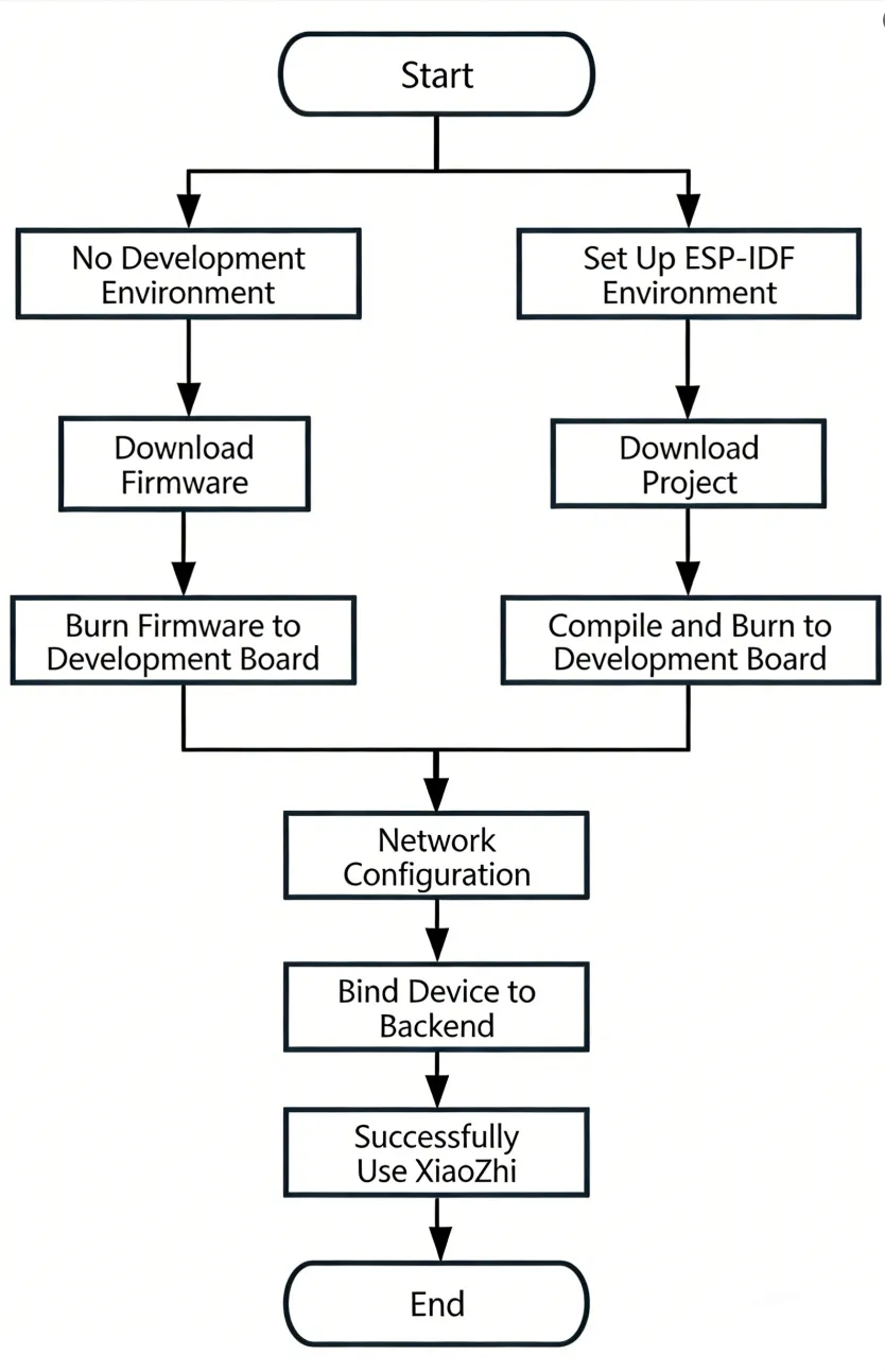
This article demonstrates how to flash firmware for Waveshare ESP32 development boards that support XiaoZhi AI, covering two methods: flashing without a development environment (directly flashing precompiled firmware) and flashing with a development environment (compiling from source and flashing).
0. Firmware Flashing Process Reference
This section uses the ESP32-S3-Touch-AMOLED-1.8 development board as an example. The steps are similar for other development boards.
Please first confirm that your hardware is listed in the XiaoZhi AI Supported Products List.
1. Flashing Without a Development Environment
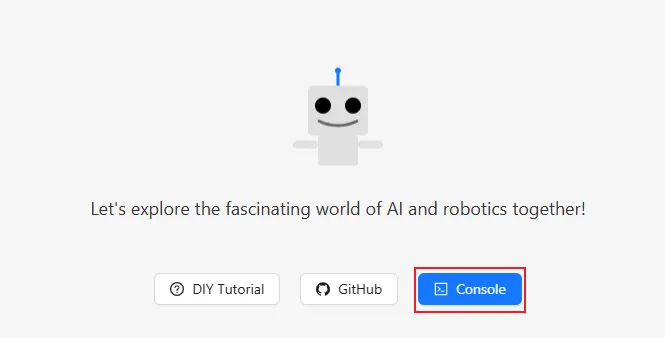
1.1 Download Firmware from XiaoZhi Official GitHub
Visit the XiaoZhi GitHub to download the firmware file for your device. Click Assets to expand the full file list:
Refer to the Flash Firmware Flashing and Erasing Tutorial to complete the firmware flashing.
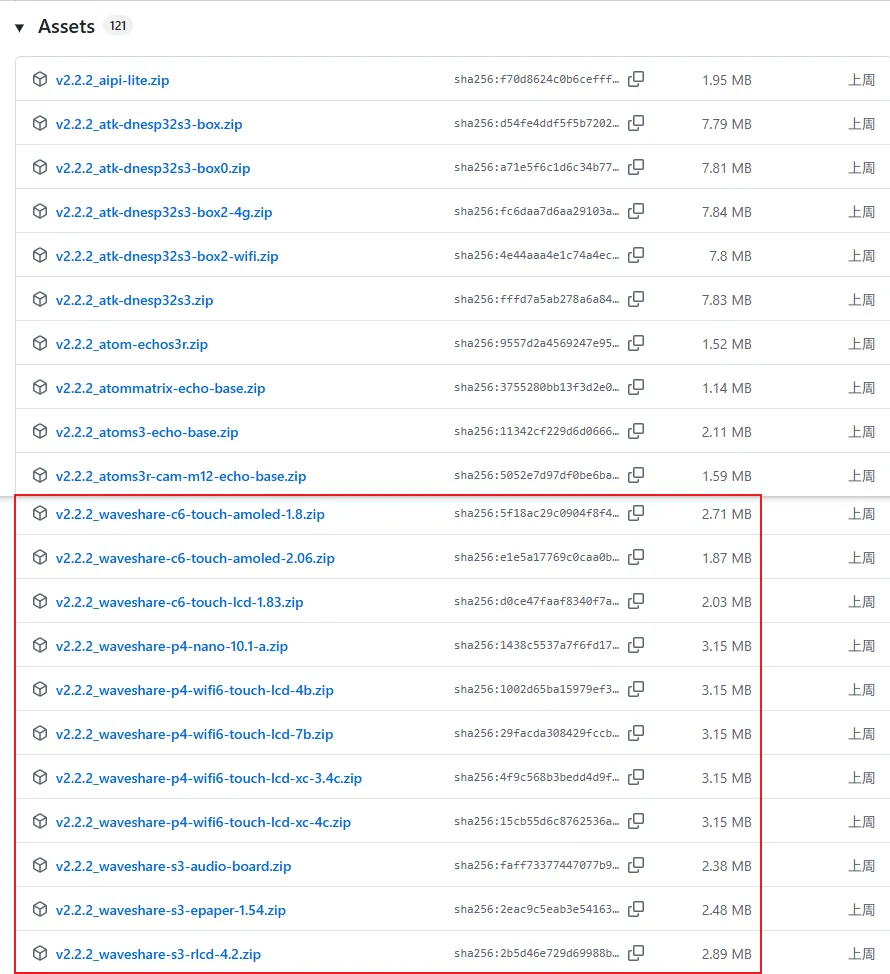
1.2 Download Firmware from Waveshare GitHub
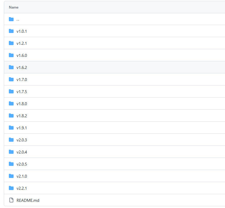
This repository aggregates firmware for Waveshare ESP32 development boards that support XiaoZhi AI. All firmware has been tested and verified on the corresponding boards, making it convenient for users to find and download. Firmware versions may be updated slightly later than the official XiaoZhi repository.
Visit the Waveshare GitHub repository and download the appropriate firmware version for your needs:
Refer to the Flash Firmware Flashing and Erasing Tutorial to complete the firmware flashing.
2. Flashing with ESP-IDF Environment
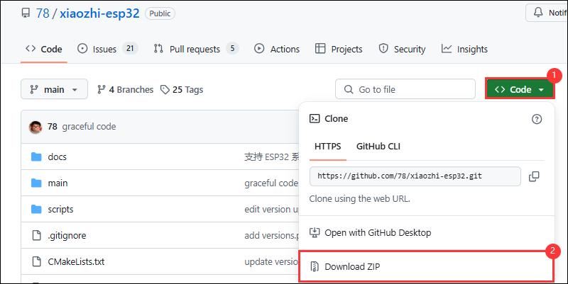
2.1 Download the Project from XiaoZhi GitHub
Visit the XiaoZhi AI Chatbot repository to download the complete project code:
2.2 Environment Setup
Refer to the ESP-IDF Environment Setup Tutorial to configure the development environment.
2.3 Configuration and Compilation
Click
 to select the target device. Choose the chip model corresponding to your development board (e.g.,
 esp32s3):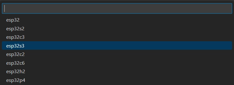 TIP
TIPWhen setting the target device, ESP-IDF will automatically configure the corresponding toolchain and libraries. This process may take some time, please be patient. For more details, please refer to the Official Documentation.
Click
 to open the ESP-IDF terminal, then execute the command
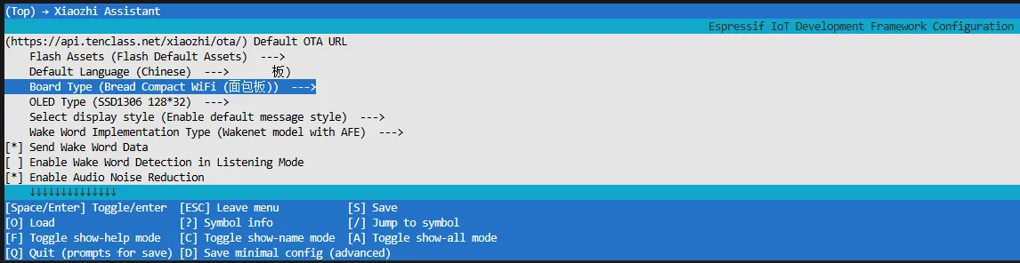
 idf.py menuconfigto enter the configuration interface. Select Xiaozhi Assistant: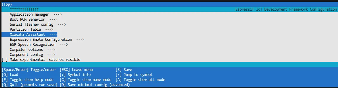
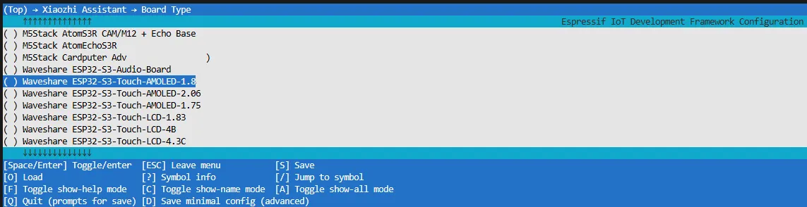
Select Board Type to choose the development board type:
Choose the product model corresponding to your development board:
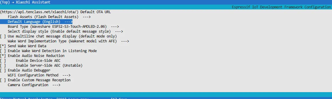
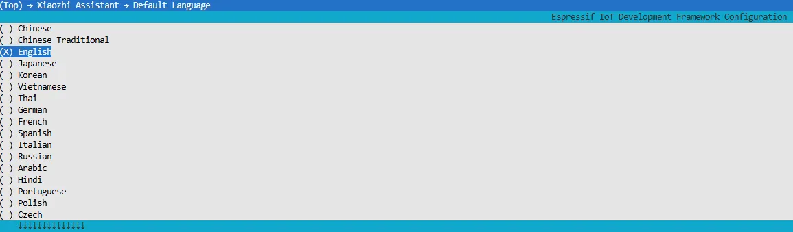
Choose XiaoZhi-AI default display language:
Press the S key to save the configuration and exit. Then click the
 to automatically complete compilation, flashing, and serial monitoring.
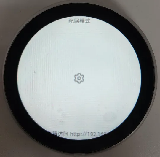
2.4 Start Network Provisioning
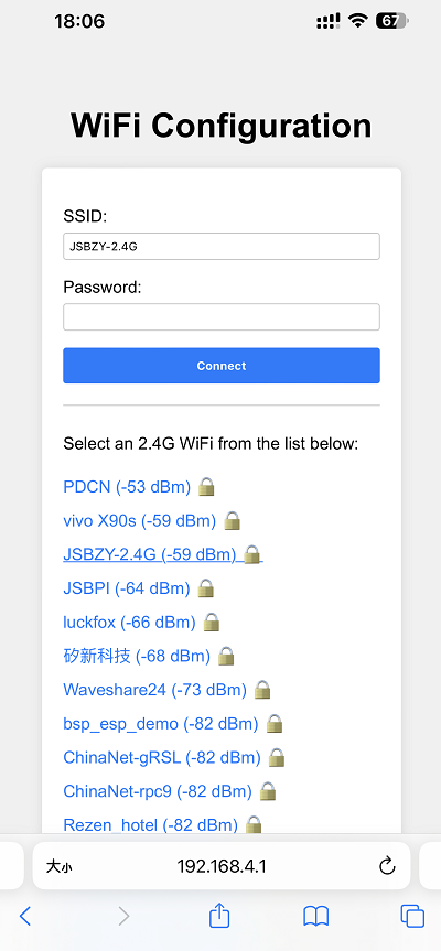
Connect your phone or computer to the device's Wi-Fi hotspot: Xiaozhi-xxxxxx. After successful connection, the configuration page should automatically pop up. If not, manually open a browser and visit
http://192.168.4.1.On the network configuration page, select the Wi-Fi name you want to connect to (only 2.4G band is supported; to connect to an iPhone hotspot, enable Max Compatibility in your phone's system settings). The SSID will be auto-filled. Enter the password and click Connect to start connecting:
2.5 Add a New Device to the Management Console
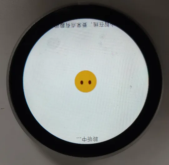
Ensure the device has successfully connected to the Internet. The device will then broadcast a 6-digit device verification code (you can wake the device again to replay the code).
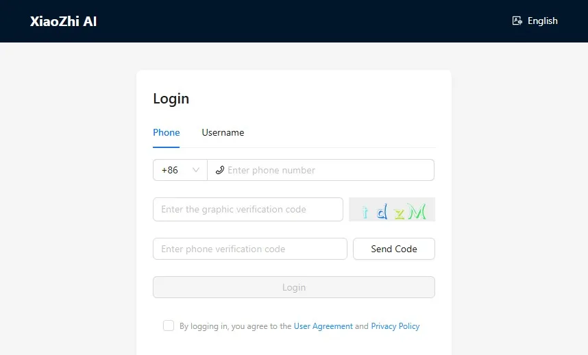
Visit the XiaoZhi AI Console. If you haven't registered, complete the registration and log in:
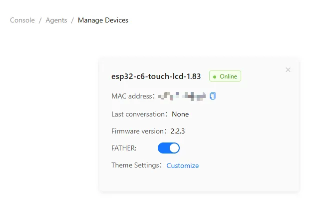
Enter the 6-digit verification code. The device will automatically activate and appear on the Device Management page, ready for normal use.
Say the wake word "Hello XiaoZhi" to wake the device and start voice conversations.
ESP32-S3-Touch-AMOLED-1.8 Button Instructions:
- BOOT button: Press to wake XiaoZhi
- PWR button: Short press to power on; long press for more than 6 seconds to power off

3. XiaoZhi Resources
Resources
1. Hardware Resources
Development Board Design Files
2. Technical Manuals
ESP32-S3 Chip Official Manuals
Datasheets
3. Example
4. Software Tools
- Arduino:
- VS Code:
- Firmware Flashing Tool:
5. Other Resource Links
Support
Monday-Friday (9:30-6:30) Saturday (9:30-5:30)
Email: services01@spotpear.com
[Tutorial Navigation]
- Onboard Resources
- Pinout Definition
- LCD Screen Specifications
- Specifications
- Dimensions
- Factory Firmware Instructions
- Working with Arduino
- Arduino Getting Started
- Setting Up the Development Environment
- Example
- ESP-IDF
- ESP-IDF Getting Started
- Setting Up the Development Environment
- Example
- XiaoZhi AI Application Tutorial
- 0. Firmware Flashing Process Reference
- 1. Flashing Without a Development Environment
- 2. Flashing with ESP-IDF Environment
- 2.1 Download the Project from XiaoZhi GitHub
- 2.2 Environment Setup
- 2.3 Configuration and Compilation
- 2.4 Start Network Provisioning
- 2.5 Add a New Device to the Management Console
- 3. XiaoZhi Resources
- Resources
- Support