


- sales/support
Google Chat:---
- sales
+86-0755-88291180
- sales01
sales@spotpear.com
- sales02
dragon_manager@163.com
- support
tech-support@spotpear.com
- CEO-Complaints
zhoujie@spotpear.com
- Only Tech-Support
WhatsApp:13246739196
- Purchase/Shipping/Refund
WhatsApp:13424403025
- HOME
- >
- ARTICLES
- >
- Common Moudle
- >
- ESP
ESP32-C6-Touch-AMOLED-1.64 User Guide
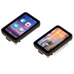
Product Overview
The ESP32-C6-Touch-AMOLED-1.64 is a microcontroller development board that supports 2.4GHz Wi-Fi 6 and Bluetooth BLE 5. It features a 1.64inch high-definition AMOLED display, capable of smoothly running GUI programs such as LVGL. The board is equipped with an IMU, TF card slot, and lithium battery charging functionality, offering rich peripheral resources. Additionally, it exposes USB, UART, I2C, and multiple MUX_GPIO interfaces, providing flexible expansion capabilities. It is an ideal choice for rapid development of HMI applications based on the ESP32-C6.
| SKU | Product |
|---|---|
| 34055 | ESP32-C6-Touch-AMOLED-1.64 |
| 34056 | ESP32-C6-Touch-AMOLED-1.64-M |
Features
- Powered by the ESP32-C6 high-performance RISC-V 32-bit single-core processor, with a main frequency of up to 160 MHz
- Onboard 320KB ROM, 512KB HP SRAM, 16KB LP SRAM, and 16MB flash
- Supports 2.4 GHz Wi-Fi 6 (802.11 b/g/n/ax), Bluetooth® 5 (LE), and IEEE 802.15.4 (supports Thread and Zigbee protocols), with optional onboard PCB antenna or external antenna connector
- Onboard 1.64inch AMOLED capacitive touchscreen, 280 × 456 resolution, 16.7M colors
- AMOLED display uses QSPI interface, capacitive touch uses I2C interface
- Onboard QMI8658 6-axis IMU (3-axis accelerometer, 3-axis gyroscope) for motion posture detection, step counting, etc.
- Onboard side-mounted PWR and BOOT buttons; BOOT supports custom button functions for flexible development
- Onboard 3.7V MX1.25 lithium battery charge/discharge interface
- Onboard TF card slot for external storage of images or files
- Onboard USB Type-C port for power supply, downloading, and debugging, facilitating development
- Exposed I2C, UART, and USB pins for connecting external devices and debugging, allowing flexible configuration of peripheral functions
- The screen features a CNC machined structural frame with edge bonding, offering a refined, soft texture and an overall aesthetic, durable appearance
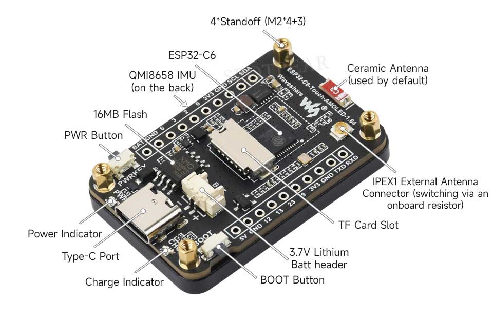
Onboard Resources
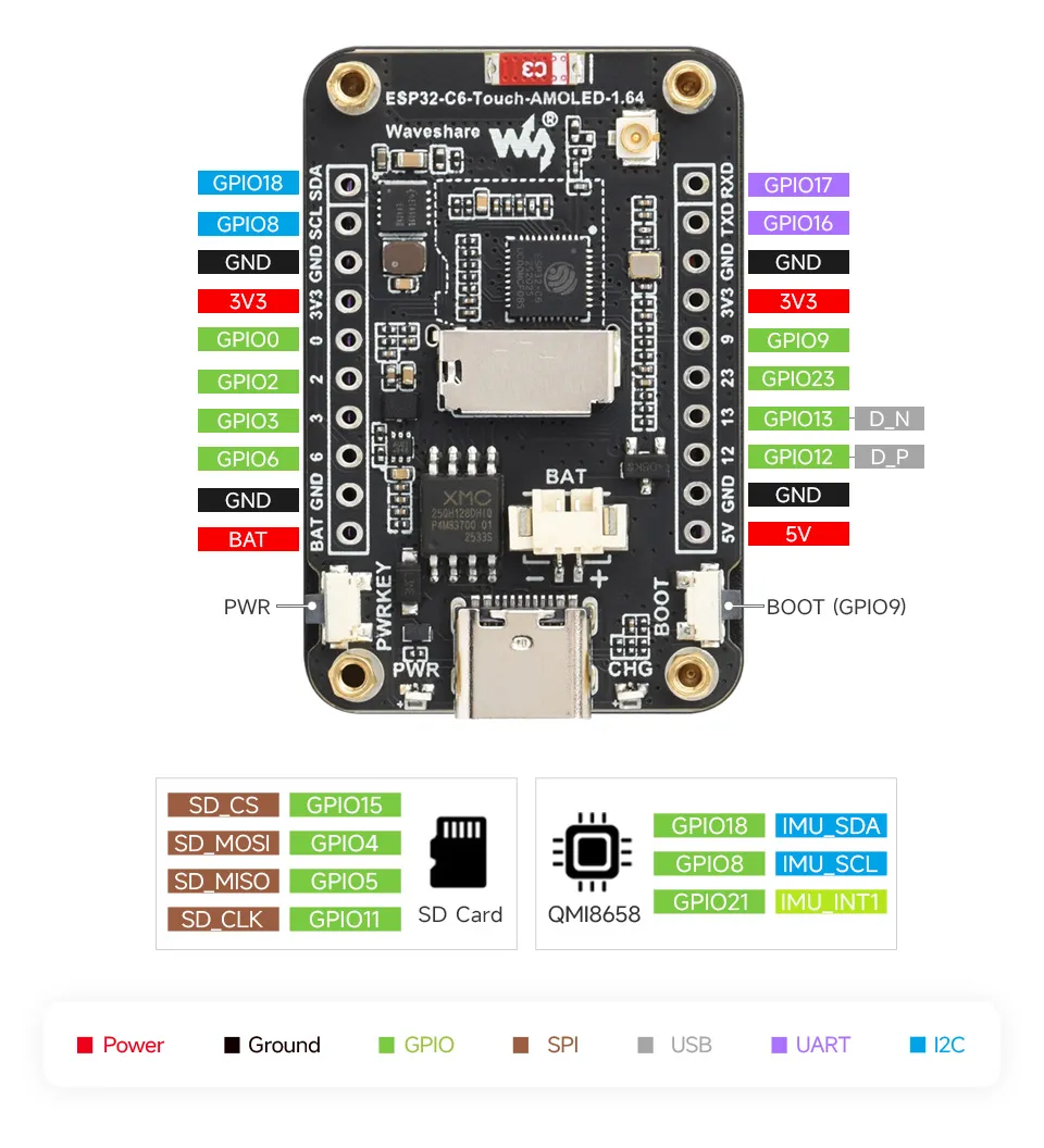
Interface Introduction
AMOLED Display Specifications
| Display Panel | AMOLED | Display Size | 1.64inch |
| Resolution | 280×456 pixels | Display Colors | 16.7M |
| Brightness | 350cd/m² | Contrast Ratio | 60000:1 |
| Communication Interface | QSPI | Driver IC | CO5300 |
| Touch IC | Supported | Driver IC | FT6146 |
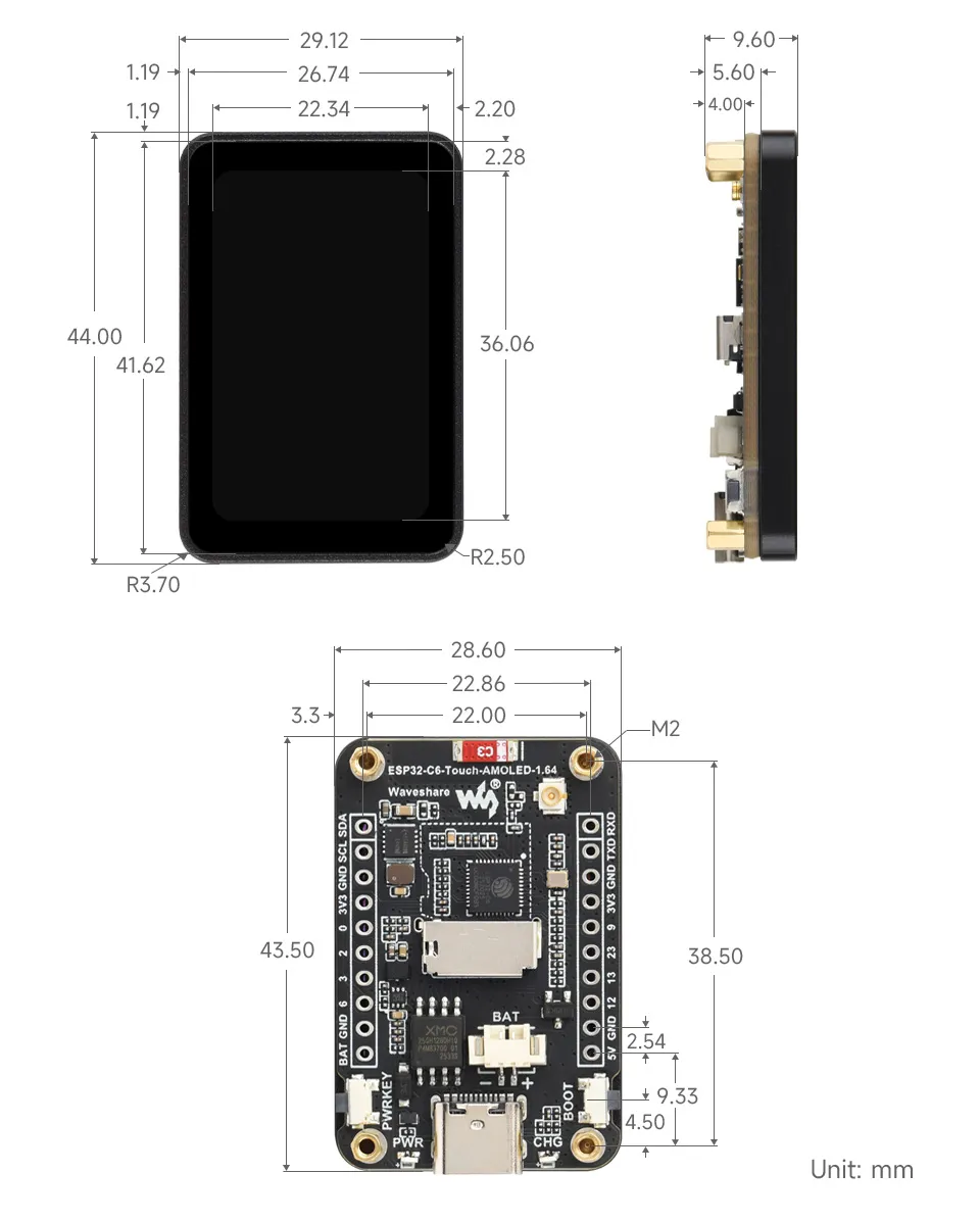
Dimensions
Working with Arduino
This chapter contains the following sections. Please read as needed:
Arduino Getting Started
New to Arduino ESP32 development and looking for a quick start? We have prepared a comprehensive Getting Started Tutorial for you.
- Section 0: Getting to Know ESP32
- Section 1: Installing and Configuring Arduino IDE
- Section 2: Arduino Basics
- Section 3: Digital Output/Input
- Section 4: Analog Input
- Section 5: Pulse Width Modulation (PWM)
- Section 6: Serial Communication (UART)
- Section 7: I2C Communication
- Section 8: SPI Communication
- Section 9: Wi-Fi Basics
- Section 10: Web Server
- Section 11: Bluetooth
- Section 12: LVGL GUI Development
- Section 13: Comprehensive Project
Note: This tutorial uses the ESP32-S3-Zero as a reference example, and all hardware code is based on its pinout. Before you start, we recommend checking the pinout of your development board to ensure the pin configuration is correct.
Setting Up Development Environment
1. Installing and Configuring Arduino IDE
For the ESP32-C6-Touch-AMOLED-1.64 development board, Arduino IDE requires arduino-esp32 version v3.2.0 or later.
Please refer to the tutorial Installing and Configuring Arduino IDE to download and install the Arduino IDE and add ESP32 support.
2. Installing Libraries
- When installing Arduino libraries, there are typically two methods: Install Online and Install Offline. If the library installation requires Install Offline, you must use the provided library file.
- For most libraries, users can easily search for and install them via the Arduino IDE's online Library Manager. However, some open-source or custom libraries are not synchronized to the Arduino Library Manager and therefore cannot be found through online search. In this case, users can only install these libraries manually via offline methods.
- The sample program package for the ESP32-C6-Touch-AMOLED-1.64 development board can be downloaded from here. The
Arduino\librariesdirectory within the package already contains all the library files required for this tutorial.
| Library/File Name | Description | Version | Installation Method |
|---|---|---|---|
| LVGL | Graphics Library | v8.4.0 | "Install Offline” |
There are strong dependencies between versions of LVGL and its driver libraries. For example, a driver written for LVGL v8 may not be compatible with LVGL v9. To ensure that the examples can be reproduced reliably, it is recommended to use the specific versions listed in the table above. Mixing different versions of libraries may lead to compilation failures or runtime errors.
3. Arduino Project Parameter Settings
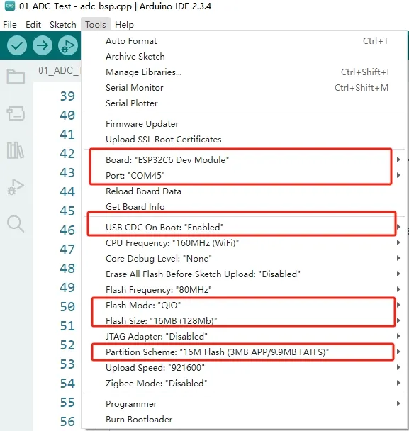
Demo
The Arduino demos are located in the Arduino/examples directory of the demo package.
| Demo | Basic Program Description | Dependency Library |
|---|---|---|
| 01_ADC_Test | Read the current system voltage value | - |
| 02_I2C_QMI8658 | Print the raw data from the IMU | - |
| 03_SD_Card | Load and display TF card information | - |
| 04_WIFI_AP | Set to AP mode, can obtain the MAC address of connected devices | - |
| 05_WIFI_STA | Set to STA mode to connect to WiFi and obtain an IP address | - |
| 06_LVGL_Test | LVGL demo | LVGL |
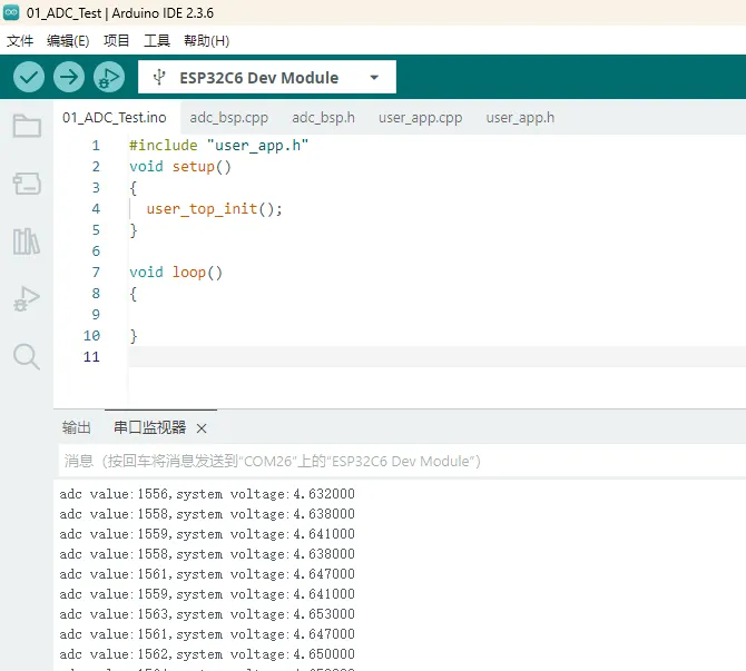
01_ADC_Test
Demo Description
- The analog voltage connected via GPIO is converted to a digital value by the ADC. The actual system voltage is then calculated and printed to the terminal.
Hardware Connection
- Connect the board to the computer using a USB cable
Code Analysis
adc_bsp_init(void): Initializes ADC1, including creating an ADC one-shot trigger unit and configuring Channel 0 of ADC1.adc_get_value(float *value,int *data): Reads the value from Channel 0 of ADC1, calculates the corresponding voltage based on the reference voltage and resolution, and stores it at the location pointed to by the passed pointer. Stores 0 if the read fails.adc_example(void* parameter): After initializing ADC1, creates an ADC task. This task reads the ADC value every second and calculates the system voltage from the raw ADC reading.
Operation Result
After the program is compiled and downloaded, you can view the printed ADC values and voltage output by opening the Serial Monitor, as shown in the following image:
When connected via USB, the measured voltage is the system voltage, around 4.65V. For detailed analysis, please refer to the schematic.
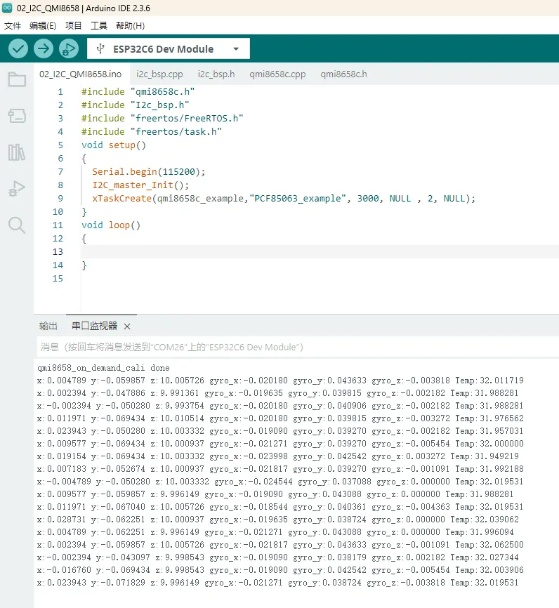
02_I2C_QMI8658
Demo Description
- Initialize the QMI8658 chip via the I2C protocol, then read the corresponding attitude information every 1 second and print it to the terminal.
Hardware Connection
- Connect the board to the computer using a USB cable
Code Analysis
qmi8658c_example(void* parameter): This function initializes the QMI8658 device. In an infinite loop, it reads and prints accelerometer, gyroscope, and temperature data every 1 second. As the board rotates faster, the gyroscope data increases accordingly. The accelerometer calculates the corresponding acceleration based on its current orientation.
Operation Result
Open the Serial Monitor to see the printed raw data from the IMU (Euler angles need to be converted by yourself), as shown in the figure below:
Data is output every 1 second. For modifications or reference, you can directly access the qmi source file.
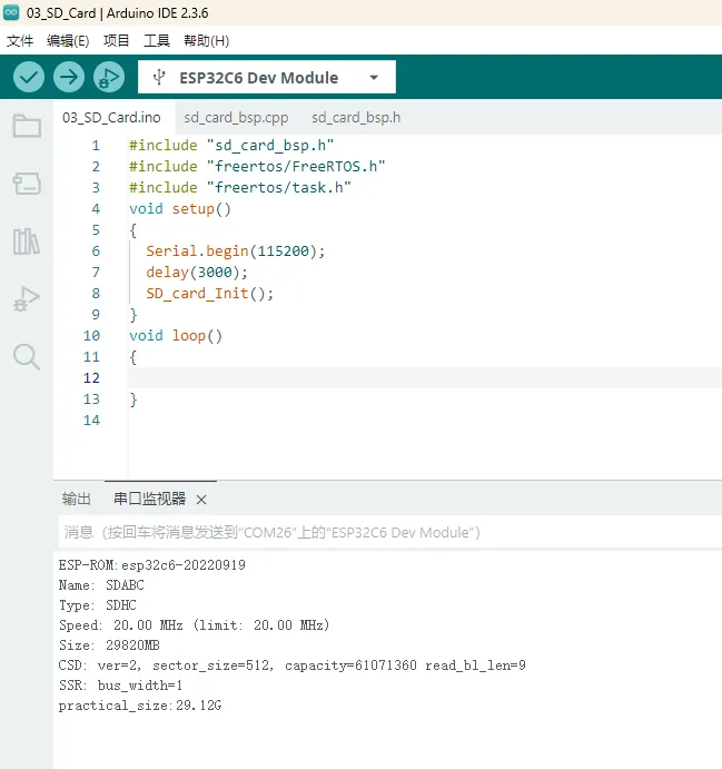
03_SD_Card
Demo Description
- Drives the TF card via SPI, and after successfully mounting the TF card, prints the TF card information to the terminal.
Hardware Connection
- The board must have a TF card inserted (capacity less than 64GB)
- Connect the board to the computer using a USB cable
Operation Result
Click to open the Serial Monitor device. You can see the output TF card information; practical_size indicates the actual capacity of the TF card, as shown below:
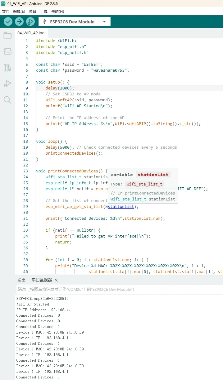
04_WIFI_AP
Demo Description
- This demo can set the development board as a hotspot, allowing phones or other devices in STA mode to connect to the development board.
Hardware Connection
- Connect the board to the computer using a USB cable
Code Analysis
- Find
ssidandpasswordin the05_WIFI_AP.inofile. Then mobile phones or other devices in STA mode can use thisssidandpasswordto connect to the development board.
Operation Result
After flashing the program, open the serial terminal. If the device is successfully connected to the hotspot, the MAC address of the device will be output, as shown in the figure:
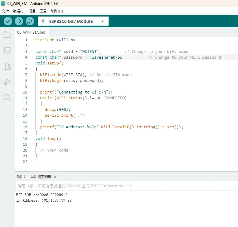
05_WIFI_STA
Demo Description
- This example sets the development board as a station, allowing it to connect to an available AP. After successful connection, it prints the obtained IP information to the terminal.
Hardware Connection
- Connect the board to the computer using a USB cable
Code Analysis
wifi_init(void): This function initializes the Wi-Fi connection of the ESP32. It sets the ESP32 to Wi-Fi station mode and attempts to connect to the specified Wi-Fi network (viassidandpassword). If successful, it prints the local IP address; if it fails to connect within a certain period (20 * 500 ms), it prints a connection failure message. The function can also enable auto-connect and auto-reconnect features.
Operation Result
The chip successfully connects to Wi-Fi in STA mode, and after clicking on the Serial Monitor, you can see the obtained IP address, as shown in the figure.
06_LVGL_Test
Demo Description
- Implements multifunctional GUI interfaces on the screen by porting LVGL.
Hardware Connection
- Connect the board to the computer using a USB cable
Code Analysis
- The display chip itself does not support hardware rotation. If rotation is required, it can be achieved through software. Find the macro definition
#define EXAMPLE_Rotate_90in thelcd_bsp.cfile and uncomment it. Software rotation performance is inferior to hardware rotation.
Operation Result
The LVGL example has relatively high requirements for RAM and ROM, so the program must be configured according to the environment setup requirements. After flashing, the device's operation effect is as follows:
User Guide
To help users quickly understand the various functions of the product, we provide a factory test example to familiarize customers with the use of each interface. Besides the ESP32-C6-Touch-AMOLED-1.64 host and the included cables, the following items are required to run the example:
Component Preparation
- ESP32-C6-Touch-AMOLED-1.64 ×1
- TF card ×1 (optional)
- 3.7V Lithium Battery ×1 (optional)
Precautions
- When using, pay attention to the PCB antenna area. Avoid having other metal or plastic parts in contact with the PCB antenna.
- The GH1.25 lithium battery connector supports only a single-cell 3.7 V lithium battery. Do not connect multiple battery packs simultaneously for charging or discharging. A single-cell capacity of 2000 mAh or less is recommended.
⚠️ USB Download Precautions (Important)
If the port is not recognized, please enter Boot mode:
- Press and hold the BOOT button
- Connect the USB cable to the computer
- Release the BOOT button
After the download is complete, restart the board to run the program.
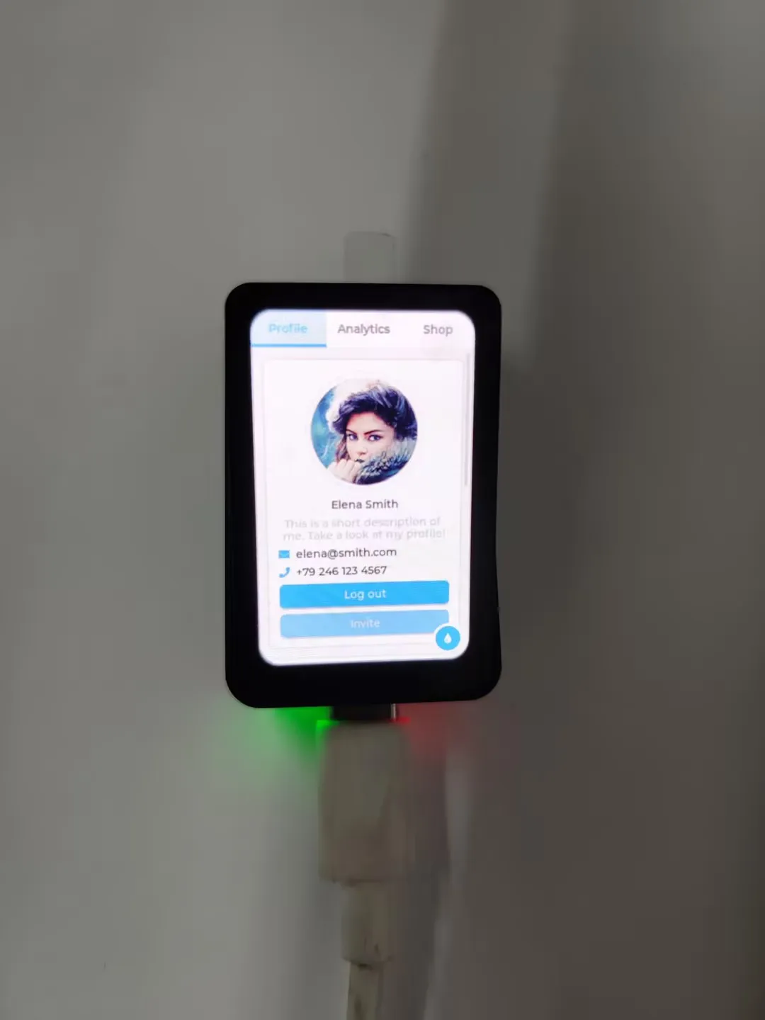
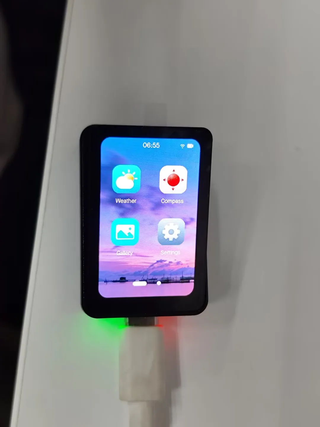
Demo Introduction
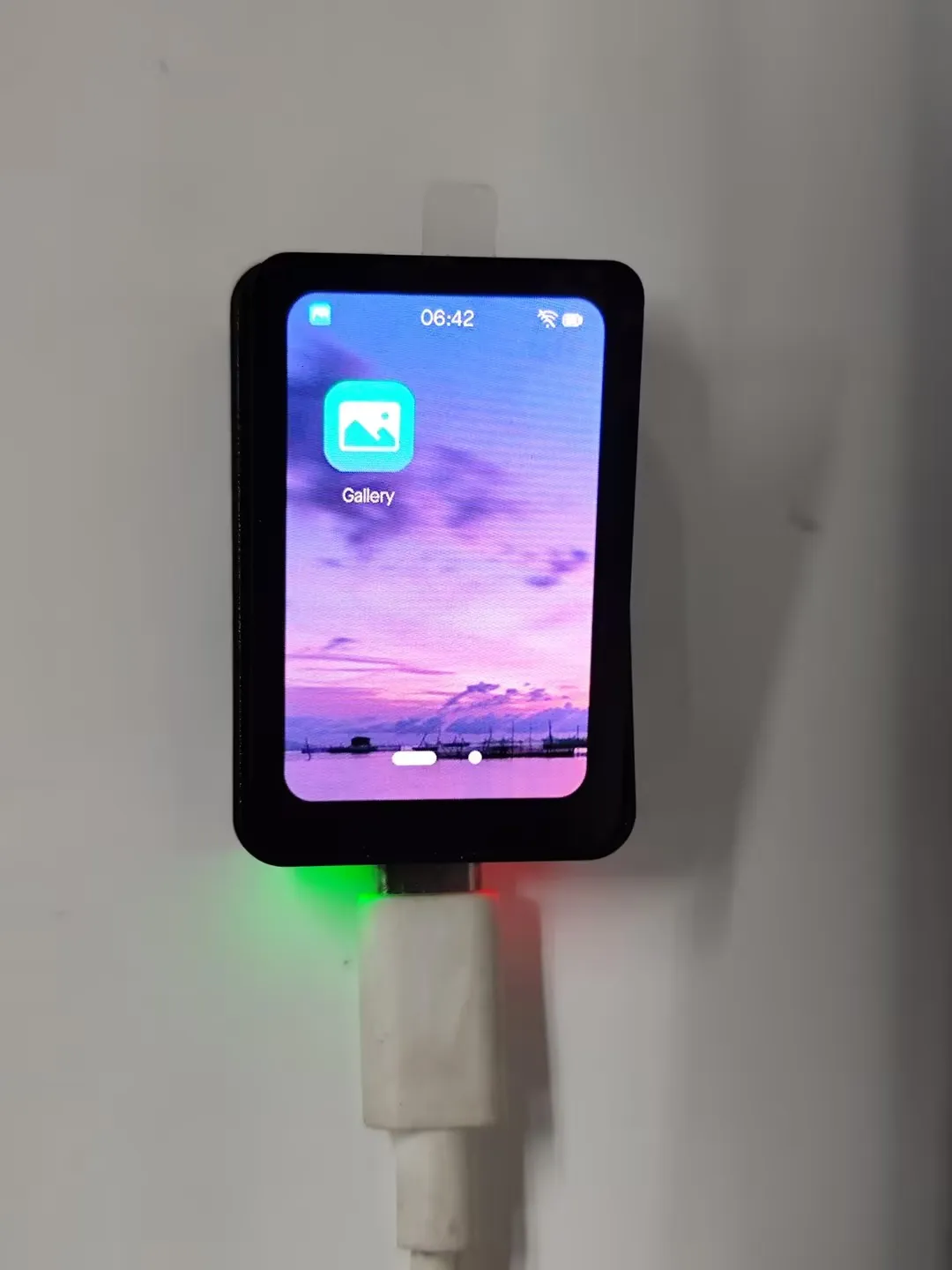
- The firmware uses the Brookesia component, showcasing various applications in an APP style, including Settings, Gallery, Weather, Gyroscope, etc.
Firmware Download
The example programs are located in the
Firmwaredirectory of the demo packageSelect the factory firmware to flash: esp32_c6_touch_amoled_1_64_factory.bin
After flashing, the screen effect is as shown:
App Example Introduction
- To exit an app, swipe up from the bottom of the screen
- Swipe up from the bottom and pause in the middle of the screen to view recently used apps. Swipe up again on an app preview to close it
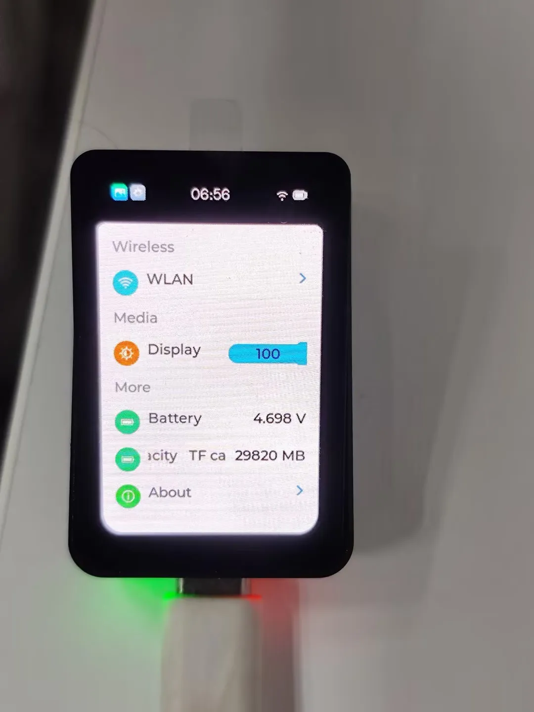
Settings App
Features Wi-Fi scanning and network configuration. Click
WIFIon the interface, thenwifi configto scan a QR code for network configurationAdjusts the backlight
Displays the battery ADC voltage
If a TF card is inserted, the TF card capacity will be displayed
Product about page, where you can view the MAC address
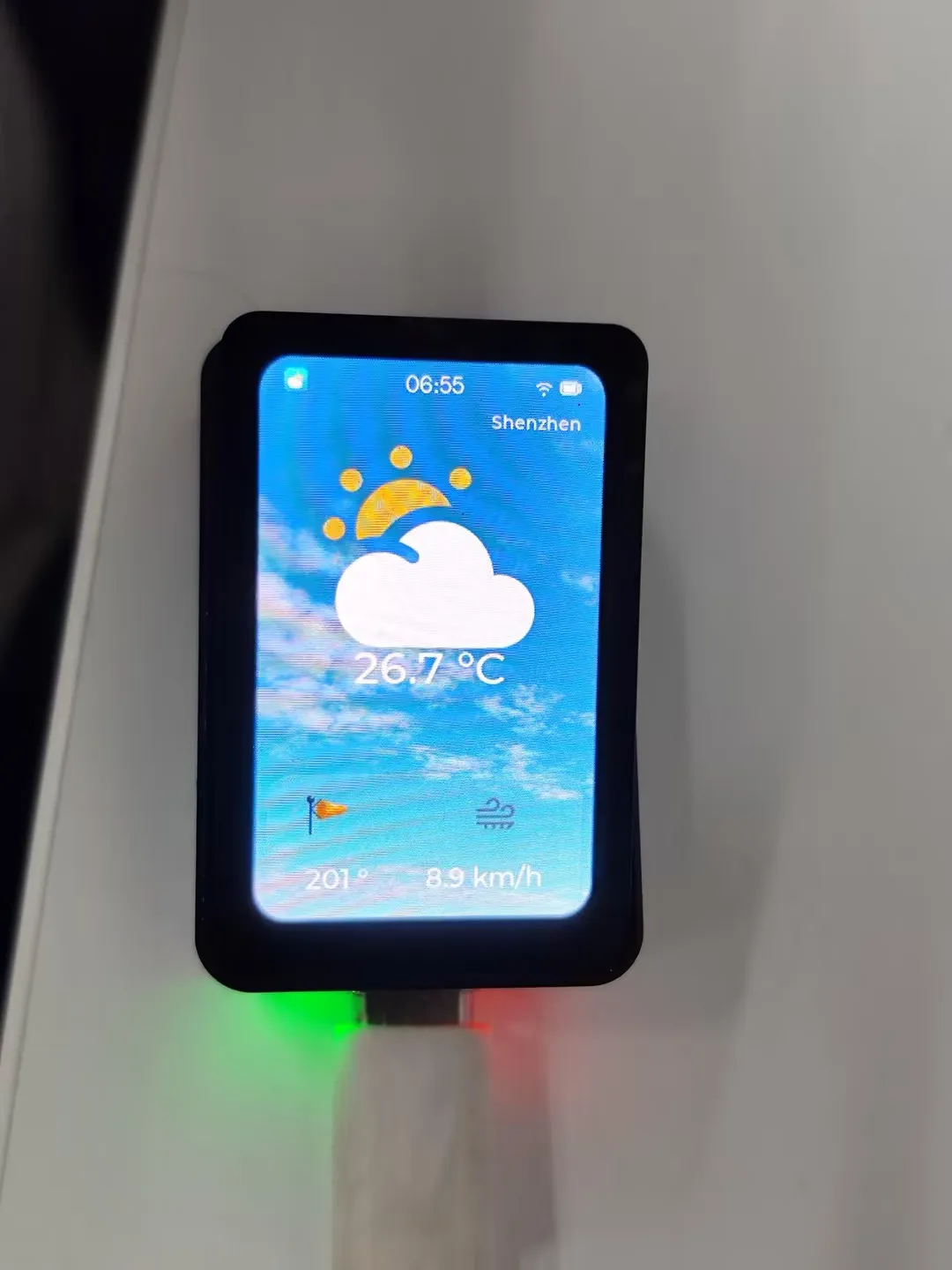
Weather APP
This example demonstrates obtaining local weather data online. An internet connection is required; otherwise, weather information cannot be retrieved.
The current program is set to fetch weather information every 5 seconds
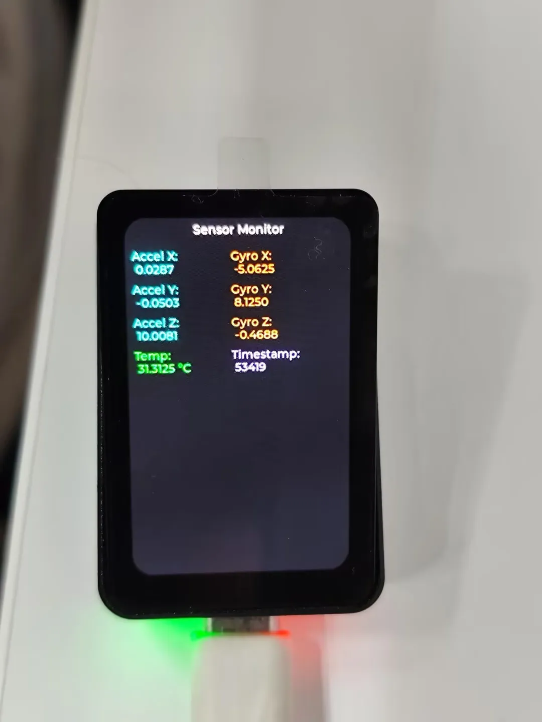
Gyroscope APP
This example demonstrates obtaining and displaying gyroscope data
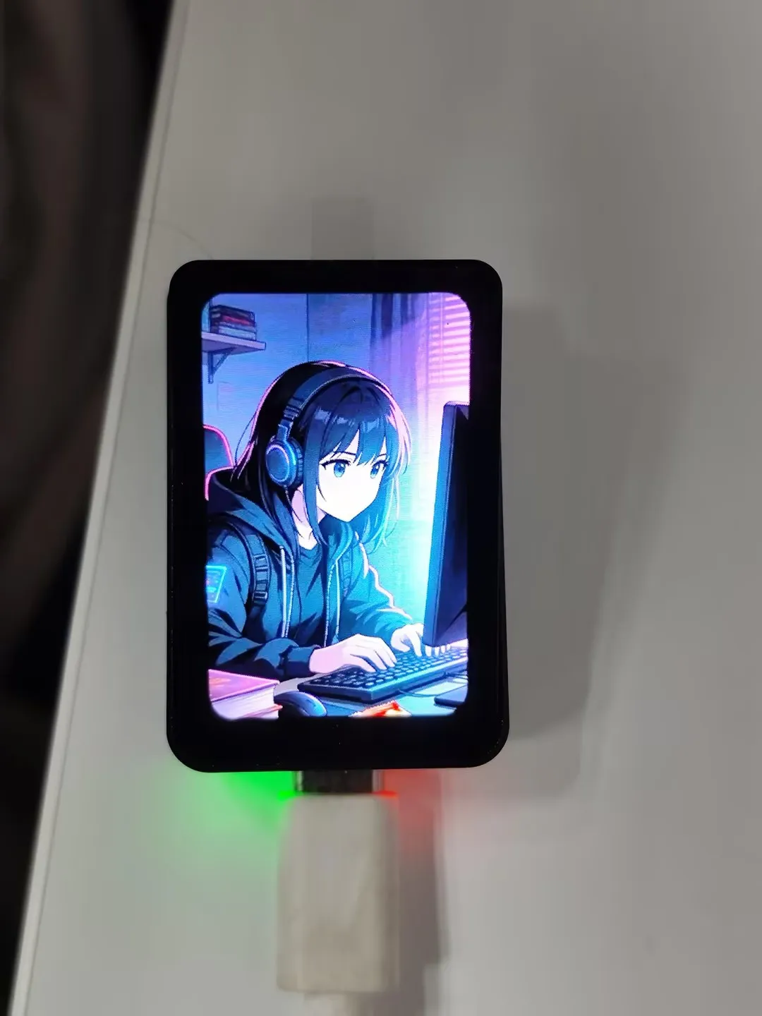
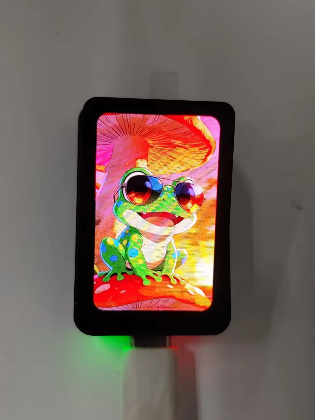
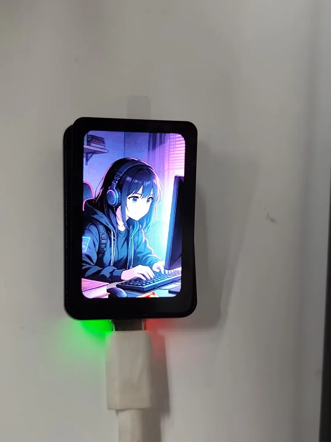
Gallery APP
This example demonstrates image display functionality
Image resources are built into the program. Swipe left or right to switch images
ESP-IDF
This chapter contains the following sections. Please read as needed:
ESP-IDF Getting Started
New to ESP32 ESP-IDF development and looking to get started quickly? We have prepared a general Getting Started Tutorial for you.
- Section 1: Environment Setup
- Section 2: Running Examples
- Section 3: Creating a Project
- Section 4: Using Components
- Section 5: Debugging
- Section 6: FreeRTOS
- Section 7: Peripherals
- Section 8: Wi-Fi Programming
- Section 9: BLE Programming
Please Note: This tutorial uses the ESP32-S3-Zero as a teaching example, and all hardware code is based on its pinout. Before you start, it is recommended that you check the pinout of your development board to ensure the pin configuration is correct.
Setting Up Development Environment
Please refer to Install ESP-IDF Development Environment.
For the ESP32-C6-Touch-AMOLED-1.64 development board, ESP-IDF version 5.5.2 or above is required.
The following guide uses Windows as an example, demonstrating development using VS Code + the ESP-IDF extension. macOS and Linux users should refer to the official documentation.
Install the ESP-IDF Development Environment
Download the installation manager from the ESP-IDF Installation Manager page. This is Espressif's latest cross-platform installer. The following steps demonstrate how to use its offline installation feature.
Click the Offline Installer tab on the page, then select Windows as the operating system and choose your desired version from the filter bar.
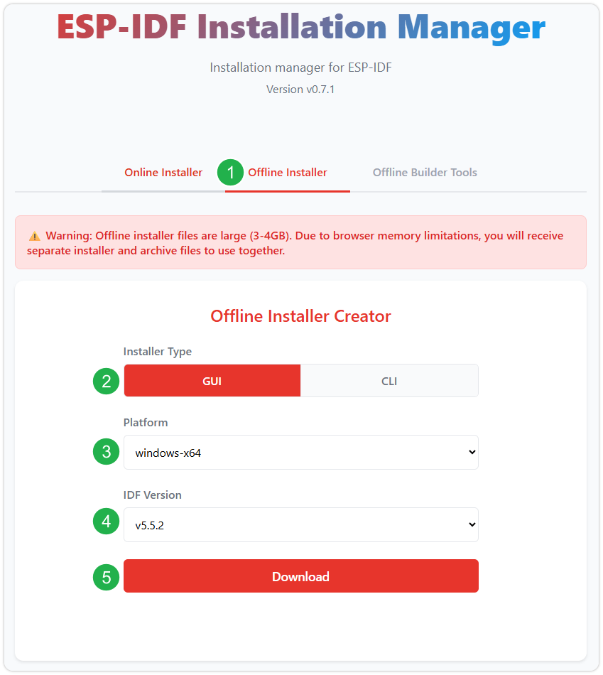
After confirming your selection, click the download button. The browser will automatically download two files: the ESP-IDF Offline Package (.zst) and the ESP-IDF Installer (.exe).
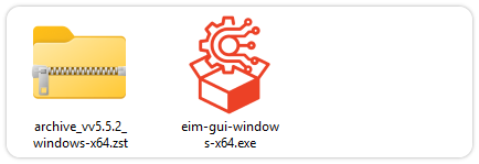
Please wait for both files to finish downloading.
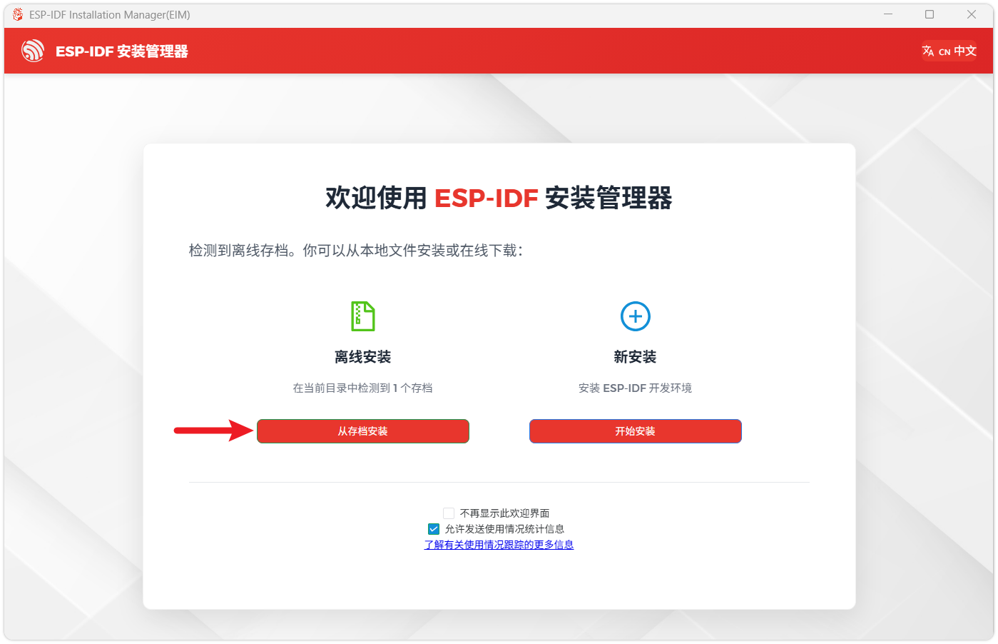
Once the download is complete, double-click to run the ESP-IDF Installer (eim-gui-windows-x64.exe).
The installer will automatically detect if the offline package exists in the same directory. Click Install from archive.
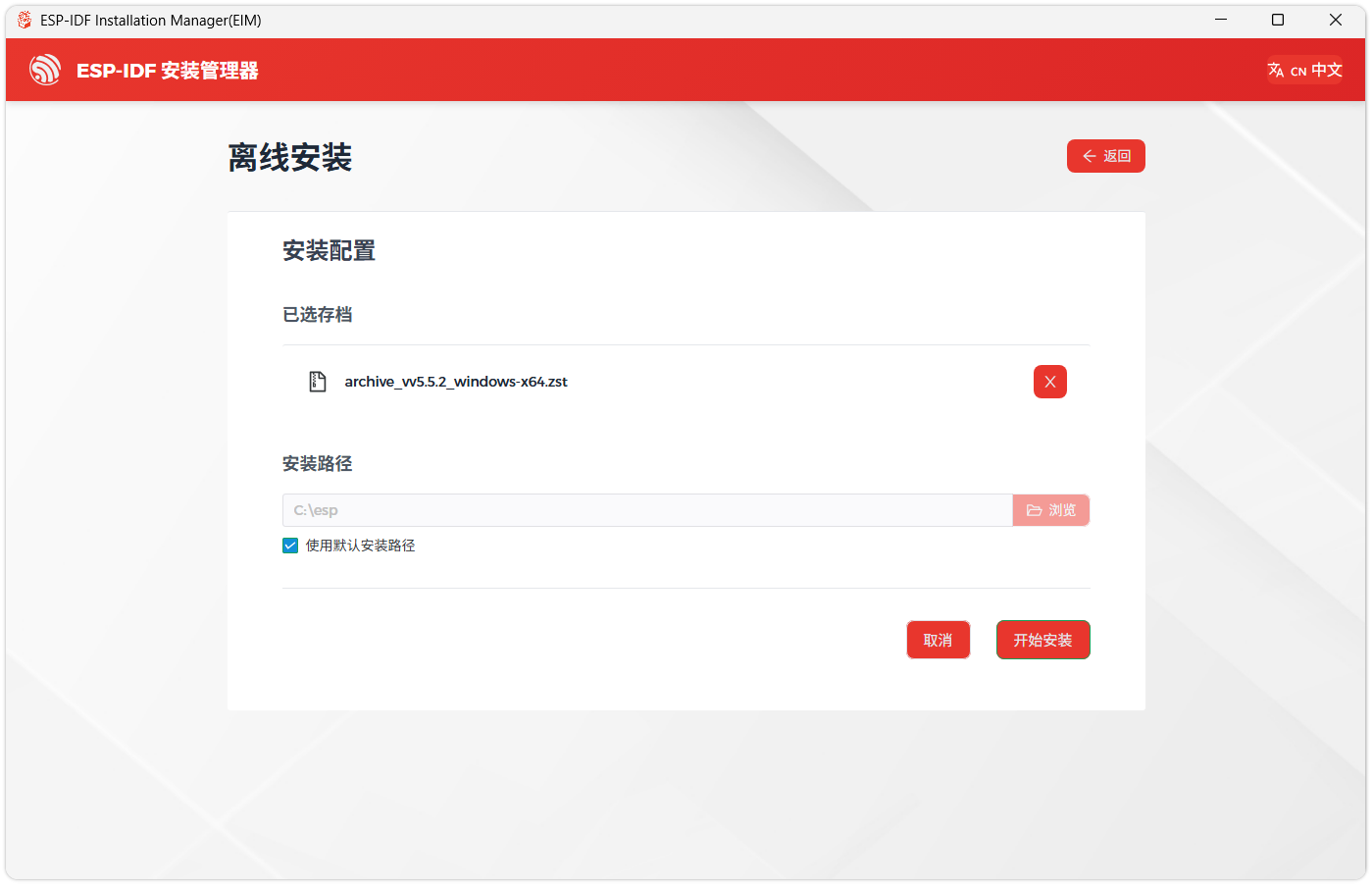
Next, select the installation path. We recommend using the default path. If you need to customize it, ensure the path does not contain Chinese characters or spaces. Click Start installation to proceed.
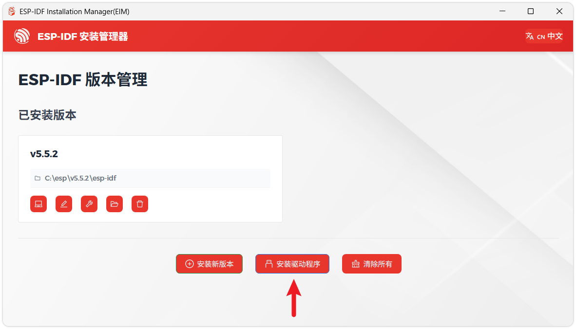
When you see the following screen, the ESP-IDF installation is successful.
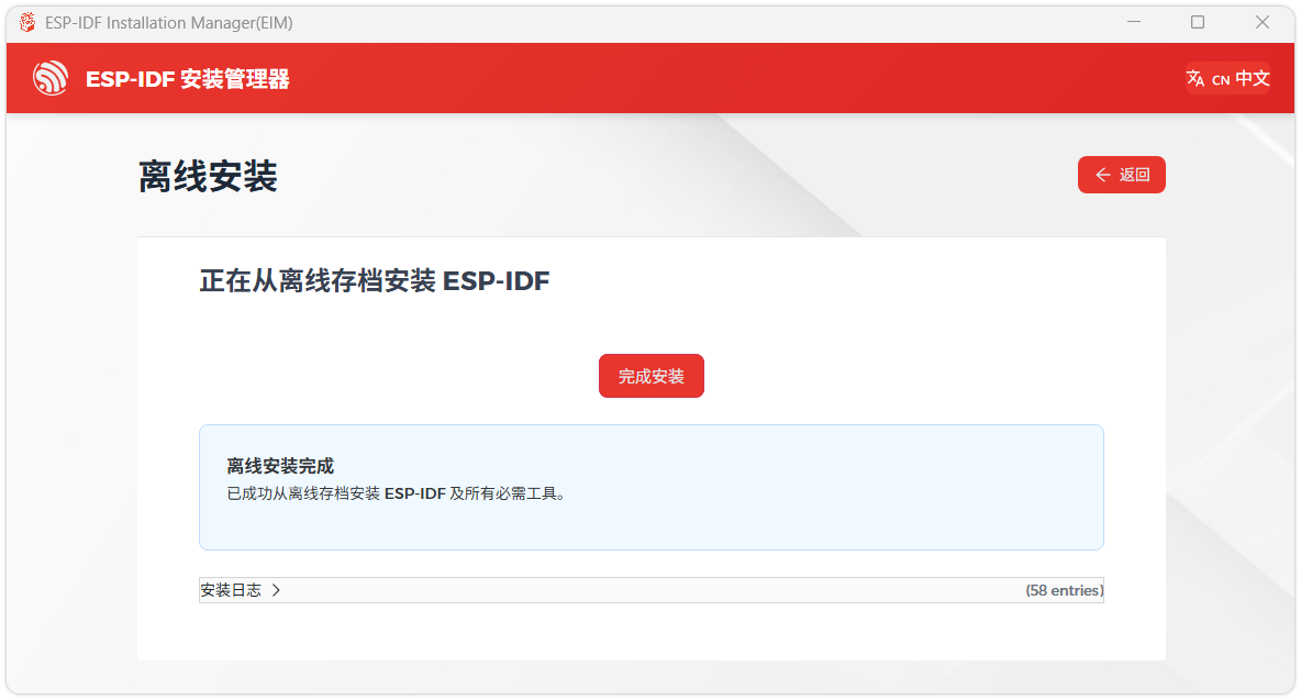
We recommend installing the drivers as well. Click Finish installation, then select Install driver.
Install Visual Studio Code and the ESP-IDF Extension
Download and install Visual Studio Code.
During installation, it is recommended to check Add "Open with Code" action to Windows Explorer file context menu to facilitate opening project folders quickly.
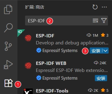
In VS Code, click the Extensions icon
 in the Activity Bar on the side (or use the shortcut Ctrl + Shift + X) to open the Extensions view.
Enter ESP-IDF in the search box, locate the ESP-IDF extension, and click Install.
For ESP-IDF extension versions ≥ 2.0, the extension will automatically detect and recognize the ESP-IDF environment installed in the previous steps, requiring no manual configuration.
Demo
| Demo | Basic Description | Dependency Library |
|---|---|---|
| 01_ADC_Test | Get the lithium battery voltage value and display it on the screen | - |
| 02_I2C_QMI8658 | Print the raw data from the IMU | - |
| 03_SD_Card | Load and display TF card information, and perform read/write tests | - |
| 04_WIFI_AP | Set to AP mode, can obtain the MAC address of connected devices | - |
| 05_WIFI_STA | Set to STA mode to connect to WiFi and obtain an IP address | - |
| 06_LVGL_Test | LVGL example | - |
| 07_brookesia_app | Brookesia picture APP example | - |
01_ADC_Test
Demo Description
- The analog voltage connected via GPIO is converted to a digital value by the ADC, then the actual system voltage is calculated and displayed on the screen.
Hardware Connection
- Connect a 3.7V lithium battery
Code Analysis
bsp_display_start(): Initialize the screen, touch, and LVGLbsp_display_backlight_on(): Turn on the backlightbat_adc_init(): Initialize ADC1, including creating an ADC single-shot trigger unit and configuring ADC1 channel 0.
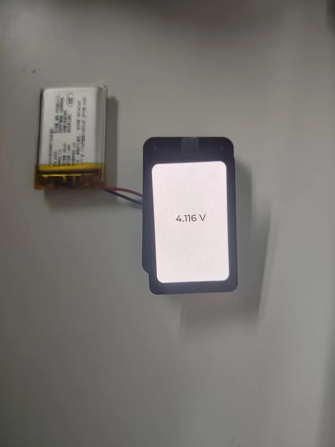
Operation Result
After compiling and downloading the program, connect the battery. The battery voltage will be displayed on the screen as shown in the figure below:
02_I2C_QMI8658
Demo Description
- Initializes the QMI8658 chip via the I2C protocol, then reads and prints the corresponding attitude information to the terminal every 1 second.
Hardware Connection
- Connect a 3.7V lithium battery
Code Analysis
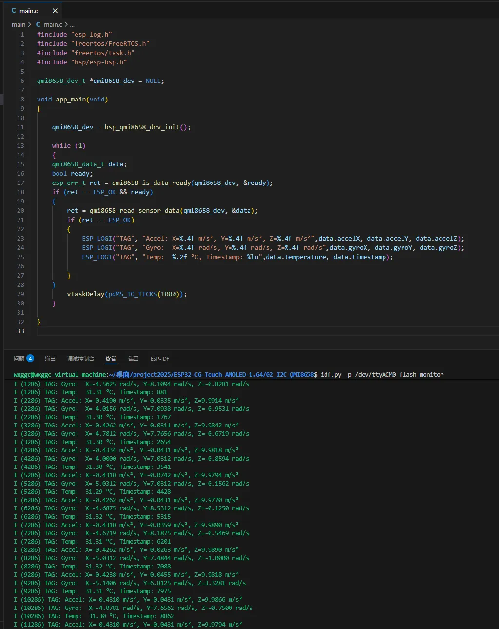
bsp_qmi8658_drv_init(): Initialize qmi8658qmi8658_is_data_ready(): Check if data is readyqmi8658_read_sensor_data(): Read gyroscope data
Operation Result
After the program is flashed, the device operation result is as follows:
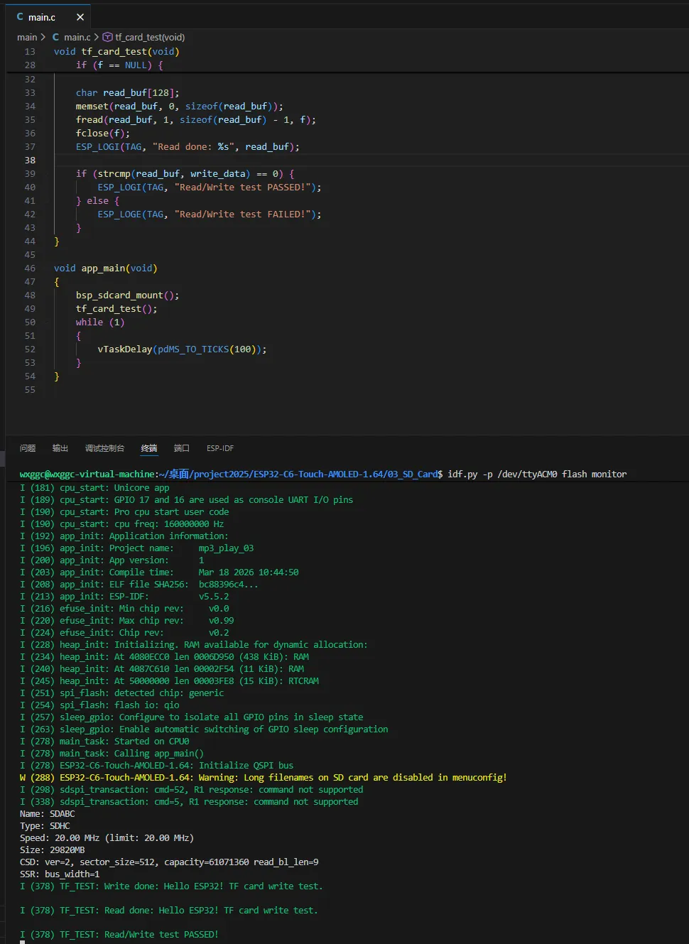
03_SD_Card
Demo Description
- Drives the TF card via SPI. After successfully mounting the TF card, prints the TF card information and read/write file test results to the terminal.
Hardware Connection
- The board must have a TF card inserted (capacity less than 64GB)
- Connect the board to the computer using a USB cable
Code Analysis
bsp_sdcard_mount(): Initialize the TF card via the SPI interfacetf_card_test(): Read/write file test
Operation Result
Click on the Serial Monitor to see the output TF card information:
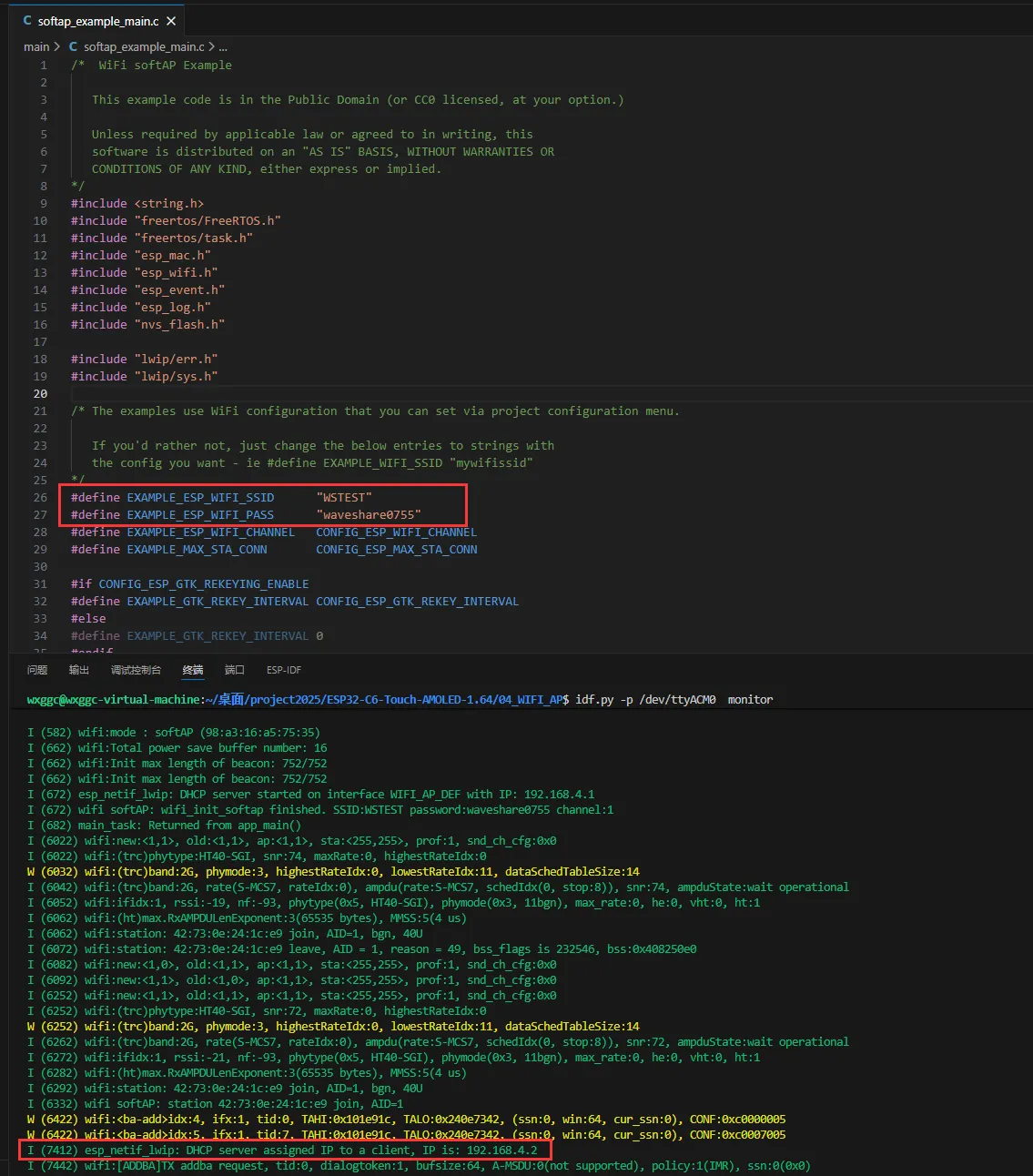
04_WIFI_AP
Demo Description
- This demo can set the development board as a hotspot, allowing phones or other devices in STA mode to connect to the development board.
Hardware Connection
- Connect the board to the computer using a USB cable
Code Analysis
- Find
SSIDandPASSWORDin thesoftap_example_main.cfile. Then mobile phones or other devices in STA mode can use thisSSIDandPASSWORDto connect to the development board.
Operation Result
Click on the Serial Monitor. If a device successfully connects to the hotspot, the IP address of that device will be output:
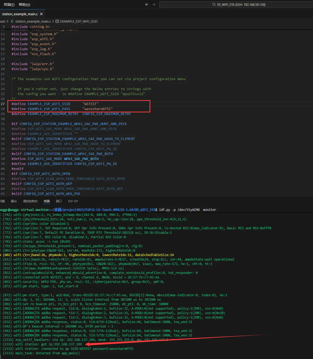
05_WIFI_STA
Demo Description
- This example configures the development board as a STA device to connect to a router, thereby accessing the system network.
Hardware Connection
- Connect the board to the computer using a USB cable
Code Analysis
- Find
SSIDandPASSWORDin thestation_example_main.cfile, and modify them to theSSIDandPasswordof an available router in the current environment.
Operation Result
After flashing the program, open the Serial Terminal. If the device successfully connects to the hotspot, the obtained IP address will be output, as shown in the figure:
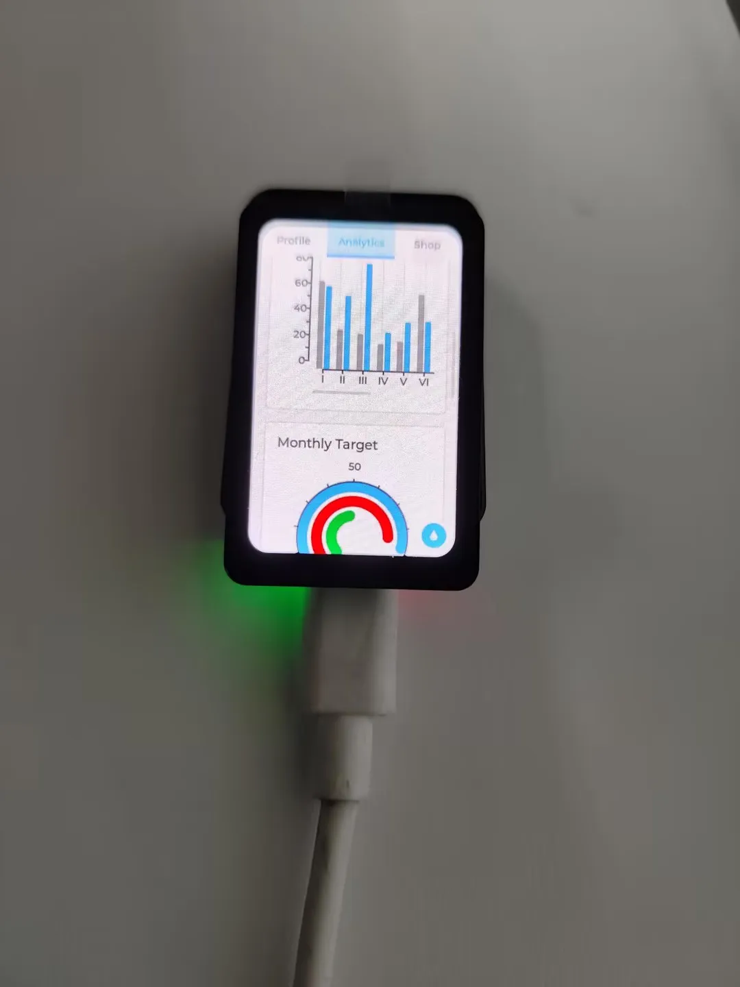
06_LVGL_Test
Demo Description
- Implements multifunctional GUI interfaces on the screen by porting LVGL.
Hardware Connection
- Connect the board to the computer using a USB cable
Code Analysis
bsp_display_start(): Initialize the screen, touch, and LVGLbsp_display_backlight_on(): Turn on the backlightlv_demo_widgets(): Load the LVGL demo program
Operation Result
After the program is flashed, the device operation result is as follows:
07_brookesia_app
Demo Description
- Implements APP-like functionality by porting
LVGLand Espressif'sbrookesiacomponent. This example only loads the picture APP.
Hardware Connection
- Connect the board to the computer using a USB cable
Code Analysis
Configure the LVGL lock for Brookesia
LvLock::registerCallbacks([](int timeout_ms) {
      esp_err_t ret = bsp_display_lock(timeout_ms);
      ESP_UTILS_CHECK_FALSE_RETURN(ret == ESP_OK, false, "Lock failed (timeout_ms: %d)", timeout_ms);

      return true;
  }, []() {
      bsp_display_unlock();
      return true;
  });
Install the APP
auto app4 = esp_brookesia::apps::Photos::requestInstance();
ESP_UTILS_CHECK_FALSE_EXIT(phone->installApp(app4),"start Drawpanel failed");
Operation Result
- After flashing the program, click the photo album icon. Swipe left or right to switch pictures. The device operation effect is as follows:
Resources
1. Hardware Resources
Development Board Design Files
2. Technical Manuals
Official ESP32-C6 Chip Manuals
Datasheets
Debugging Tools
- Serial Debugging: Serial and Network Debug Assistant Assistant
- Flash Download: Flash Debug Tool
- Bluetooth Debugging: Bluetooth Debug Assistant
3. Demo
Support
Monday-Friday (9:30-6:30) Saturday (9:30-5:30)
Email: services01@spotpear.com
[Tutorial Navigation]
- Product Overview
- Features
- Onboard Resources
- Interface Introduction
- Dimensions
- Working with Arduino
- Arduino Getting Started
- Setting Up Development Environment
- 1. Installing and Configuring Arduino IDE
- 2. Installing Libraries
- 3. Arduino Project Parameter Settings
- Demo
- User Guide
- ESP-IDF
- Resources
- Support