


- sales/support
Google Chat:---
- sales
+86-0755-88291180
- sales01
sales@spotpear.com
- sales02
dragon_manager@163.com
- support
tech-support@spotpear.com
- CEO-Complaints
zhoujie@spotpear.com
- Only Tech-Support
WhatsApp:13246739196
- Purchase/Shipping/Refund
WhatsApp:13424403025
- HOME
- >
- ARTICLES
- >
- Common Moudle
- >
- ESP
ESP32-S3-Touch-AMOLED-1.43C User Guide
Features
- Powered by the ESP32-S3-PICO-1-N8R8 high-performance Xtensa 32-bit LX7 dual-core processor, with a main frequency of up to 240 MHz
- Supports 2.4GHz Wi-Fi (802.11 b/g/n) and Bluetooth 5 (LE) with an onboard antenna
- Built-in 512KB SRAM and 384KB ROM, stacked 8MB Flash and 8MB PSRAM
- Features a Type-C interface, enhancing user convenience and device compatibility
- Onboard 1.43inch capacitive touch high-definition AMOLED display, 466 × 466 resolution, 16.7M colors, enabling clear display of color images
- AMOLED screen offers higher contrast, wider viewing angles, rich colors, and better visual effects. Also features slim design, low power consumption, fast response, and high flexibility
- Built-in CO5300 driver chip and CST820 capacitive touch controller chip, communicating via QSPI and I2C interfaces respectively, minimizing the use of I/O pins
- Equipped with a dual-microphone array for audio algorithms such as noise reduction and echo cancellation, suitable for accurate speech recognition and near-field/far-field wake-up applications
- Onboard BOOT button for custom functions, convenient for custom function development
- Onboard 3.7V MX1.25 lithium battery charge/discharge interface
- Exposes 1-ch I2C, 1-ch USB and 1-ch UART pads for external devices connection and debugging, enabling flexible peripheral configuration
Onboard Resources
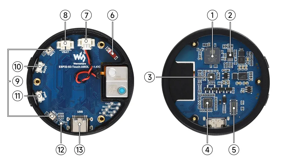
- ESP32-S3-PICO-1-N8R8 Wi-Fi and Bluetooth SoC, 240MHz operating frequency, stacked 8MB PSRAM and 8MB Flash
- Speaker Amplifier Chip Professional audio power amplifier chip providing clear and full audio output, ensuring a high-quality external playback experience
- ES8311 Low-power audio codec chip
- ES7210 Echo Cancellation Chip Used for echo cancellation to improve audio capture accuracy
- Screen Interface Exclusively for connecting the screen
- Onboard Chip Antenna Supports 2.4GHz Wi-Fi (802.11 b/g/n) and Bluetooth 5 (LE)
- MX1.25 Speaker Interface Audio output signal, supports external speaker
- MX1.25 Lithium Battery Header MX1.25 2PIN connector for connecting a 3.7V lithium battery, supports charging and discharging
- Dual Microphone Array Design Dual microphone array, supporting richer voice interaction functions
- BOOT Button Hold the BOOT button, then press PWR button to power on and enter download mode
- PWR Button Powers on automatically when connected; short press to power on, long press to power off
- Programmable LED Connected to GPIO5, user-definable function
- Type-C Port ESP32-S3 USB Type-C interface for program upload and serial log output
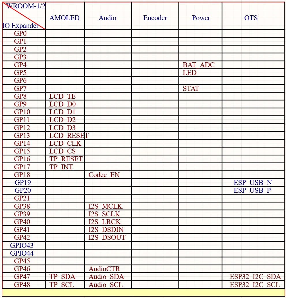
Interface Introduction
AMOLED Display Specifications
| Parameter | Value | Parameter | Value |
|---|---|---|---|
| Display Panel | AMOLED | Display Size | 1.43 inches |
| Display Resolution | 466 × 466 pixels | Display Colors | 16.7M |
| Display Brightness | 600 cd/m² | Contrast Ratio | 10000:1 |
| Communication Interface | QSPI | Driver IC | CO5300 |
| Touch Support | Yes | Touch Controller IC | CST820 |
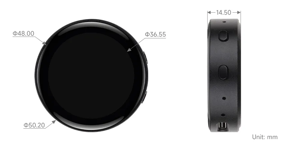
Dimensions
Working with Arduino
This chapter contains the following sections. Please read as needed:
Arduino Getting Started
New to Arduino ESP32 development and looking for a quick start? We have prepared a comprehensive Getting Started Tutorial for you.
- Section 0: Getting to Know ESP32
- Section 1: Installing and Configuring Arduino IDE
- Section 2: Arduino Basics
- Section 3: Digital Output/Input
- Section 4: Analog Input
- Section 5: Pulse Width Modulation (PWM)
- Section 6: Serial Communication (UART)
- Section 7: I2C Communication
- Section 8: SPI Communication
- Section 9: Wi-Fi Basics
- Section 10: Web Server
- Section 11: Bluetooth
- Section 12: LVGL GUI Development
- Section 13: Comprehensive Project
Note: This tutorial uses the ESP32-S3-Zero as a reference example, and all hardware code is based on its pinout. Before you start, we recommend checking the pinout of your development board to ensure the pin configuration is correct.
Setting Up Development Environment
1. Installing and Configuring Arduino IDE
For the ESP32-S3-Touch-AMOLED-1.43C development board, Arduino IDE requires arduino-esp32 version v3.3.0 or later.
Please refer to the tutorial Installing and Configuring Arduino IDE to download and install the Arduino IDE and add ESP32 support.
2. Installing Libraries
- When installing Arduino libraries, there are typically two methods: Install Online and Install Offline. If the library installation requires Install Offline, you must use the provided library file.
- For most libraries, users can easily search for and install them via the Arduino IDE's online Library Manager. However, some open-source or custom libraries are not synchronized to the Arduino Library Manager and therefore cannot be found through online search. In this case, users can only install these libraries manually via offline methods.
- The sample program package for the ESP32-S3-Touch-AMOLED-1.43C development board can be downloaded from here. The
Arduino\librariesdirectory within the package already contains all the library files required for this tutorial.
| Library/File Name | Description | Version | Installation Method |
|---|---|---|---|
| LVGL | Graphics Library | v8.3.11/v9.5.0 | "Install Offline" |
There are strong dependencies between versions of LVGL and its driver libraries. For example, a driver written for LVGL v8 may not be compatible with LVGL v9. To ensure that the examples can be reproduced reliably, it is recommended to use the specific versions listed in the table above. Mixing different versions of libraries may lead to compilation failures or runtime errors.
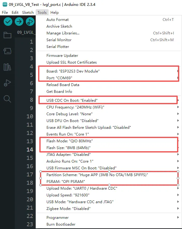
3. Arduino Project Parameter Settings
Demo
The Arduino demos are located in the Arduino/examples directory of the demo package.
| Demo | Basic Program Description | Dependency Library |
|---|---|---|
| 01_ADC_Test | Get the voltage value of the lithium battery | - |
| 02_WIFI_AP | Set to AP mode to obtain the IP address of the access device | - |
| 03_WIFI_STA | Set to STA mode to connect to Wi-Fi and obtain an IP address | - |
| 04_Audio_Test | Play the sound recorded by the microphone through the speaker | LVGL V9.5.0 |
| 05_LVGL_V8_Test | LVGLV8 demo | LVGL V8.3.11 |
| 06_LVGL_V9_Test | LVGLV9 demo | LVGL V9.5.0 |
01_ADC_Test
Demo Description
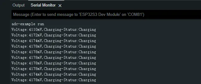
- The analog voltage connected through the GPIO is converted to digital by the ADC, and then the actual lithium battery voltage is calculated and printed to the terminal.
Hardware Connection
- Connect the board to the computer using a USB cable
Code Analysis
printf("adc-example run\n"); // Terminal output information
bsp_batt_init();             // Initialize ADC channel
bsp_batt_get_voltage();      // Get battery voltage
bsp_batt_get_status();       // Get battery charging status
Operation Result
After the program is compiled and uploaded, open the serial monitor to see the printed output of the lithium battery voltage and charging information, as shown in the following figure:
02_WIFI_AP
Demo Description
- This demo can set the development board as a hotspot, allowing phones or other devices in STA mode to connect to the development board.
Hardware Connection
- Connect the board to the computer using a USB cable
Code Analysis
In the
02_WIFI_AP.inofile, locatessidandpassword. Phones or other STA mode devices can then connect to the board using this SSID and password.const char *ssid = "ESP32_AP";const char *password = "12345678";
Operation Result
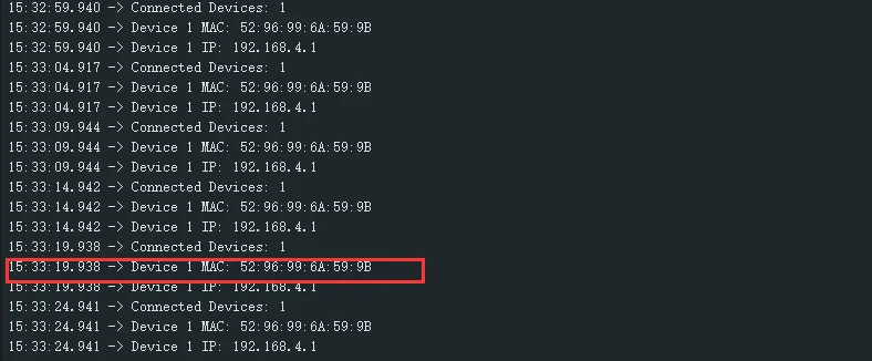
After flashing the program, open the Serial Terminal. If a device successfully connects to the hotspot, the MAC address of that device will be output, as shown:
03_WIFI_STA
Demo Description
- This example configures the development board as a STA device to connect to a router, thereby accessing the system network.
Hardware Connection
- Connect the board to the computer using a USB cable
Code Analysis
In the
03_WIFI_STA.inofile, locatessidandpassword, and modify them to match the SSID and Password of an available router in the current environment.const char *ssid = "you_ssid";const char *password = "you_password";
Operation Result
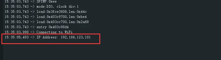
After flashing the program, open the Serial Terminal. If the device successfully connects to the hotspot, the obtained IP address will be output, as shown in the figure:
04_Audio_Test
Demo Description
- Demonstrate how to acquire microphone data, play music, and other functions.
Hardware Connection
- Connect the board to the computer using a USB cable
Code Analysis
bsp_broolesia_display_init();                              // Screen initialization
speaker = bsp_audio_codec_speaker_init();                  // Obtain playback handle
microphone = bsp_audio_codec_microphone_init();            // Obtain recording handle
boot_button_ = new Button(BUTTON_0_GPIO_PIN);Instantiate button
InitializeButtons();                                       // Button callback initialization
ESP_ERROR_CHECK(esp_codec_dev_open(speaker, &fs));         // Open playback
ESP_ERROR_CHECK(esp_codec_dev_open(microphone, &fs));      // Open recording
ESP_ERROR_CHECK(esp_codec_dev_set_out_vol(speaker, 100));  // Set playback volume
ESP_ERROR_CHECK(esp_codec_dev_set_in_gain(microphone,35)); // Set recording gain
Operation Result
After the program is flashed, the screen displays as shown:
TIP- Press the BOOT button once to record for 3 seconds; after recording ends, the recording is played back automatically.
- Double-click the BOOT button to play a piece of music; press and hold the BOOT button to interrupt playback.

05_LVGL_V8_Test
Demo Description
- Implements various multifunctional GUI interfaces on the screen by porting LVGL V8.
Hardware Connection
- Connect the board to the computer using a USB cable
Code Analysis
#define BACKLIGHT_EN 1                // Macro definition, enable backlight test, enabled by default
bsp_broolesia_display_init();         // Initialize screen and LVGL
if(bsp_display_lock(-1) == ESP_OK) {  // Wait for lock
  lv_demo_widgets();                  // LVGL default UI
  bsp_display_unlock();               // Release lock
}
Operation Result
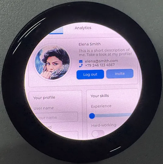
After the program is flashed, the device operation result is as follows:

06_LVGL_V9_Test
Demo Description
- Implements various multifunctional GUI interfaces on the screen by porting LVGL V9.
Hardware Connection
- Connect the board to the computer using a USB cable
Code Analysis
#define BACKLIGHT_EN 1               // Macro definition, enable backlight test, enabled by default
bsp_broolesia_display_init();        // Initialize screen and LVGL
if(bsp_display_lock(-1) == ESP_OK) { // Wait for lock
  lv_demo_widgets();                 // LVGL default UI
  bsp_display_unlock();              // Release lock
}
Operation Result
After the program is flashed, the device operation result is as follows:
ESP-IDF
This chapter contains the following sections. Please read as needed:
ESP-IDF Getting Started
New to ESP32 ESP-IDF development and looking to get started quickly? We have prepared a general Getting Started Tutorial for you.
- Section 1: Environment Setup
- Section 2: Running Examples
- Section 3: Creating a Project
- Section 4: Using Components
- Section 5: Debugging
- Section 6: FreeRTOS
- Section 7: Peripherals
- Section 8: Wi-Fi Programming
- Section 9: BLE Programming
Please Note: This tutorial uses the ESP32-S3-Zero as a teaching example, and all hardware code is based on its pinout. Before you start, it is recommended that you check the pinout of your development board to ensure the pin configuration is correct.
Setting Up Development Environment
The following guide uses Windows as an example, demonstrating development using VS Code + the ESP-IDF extension. macOS and Linux users should refer to the official documentation.
Install the ESP-IDF Development Environment
Download the installation manager from the ESP-IDF Installation Manager page. This is Espressif's latest cross-platform installer. The following steps demonstrate how to use its offline installation feature.
Click the Offline Installer tab on the page, then select Windows as the operating system and choose your desired version from the filter bar.
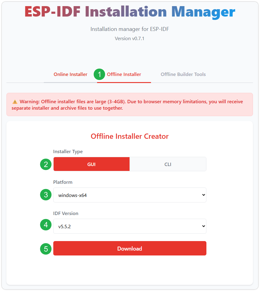
After confirming your selection, click the download button. The browser will automatically download two files: the ESP-IDF Offline Package (.zst) and the ESP-IDF Installer (.exe).
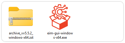
Please wait for both files to finish downloading.
Once the download is complete, double-click to run the ESP-IDF Installer (eim-gui-windows-x64.exe).
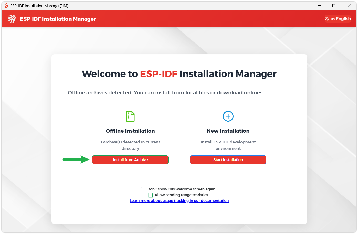
The installer will automatically detect if the offline package exists in the same directory. Click Install from archive.
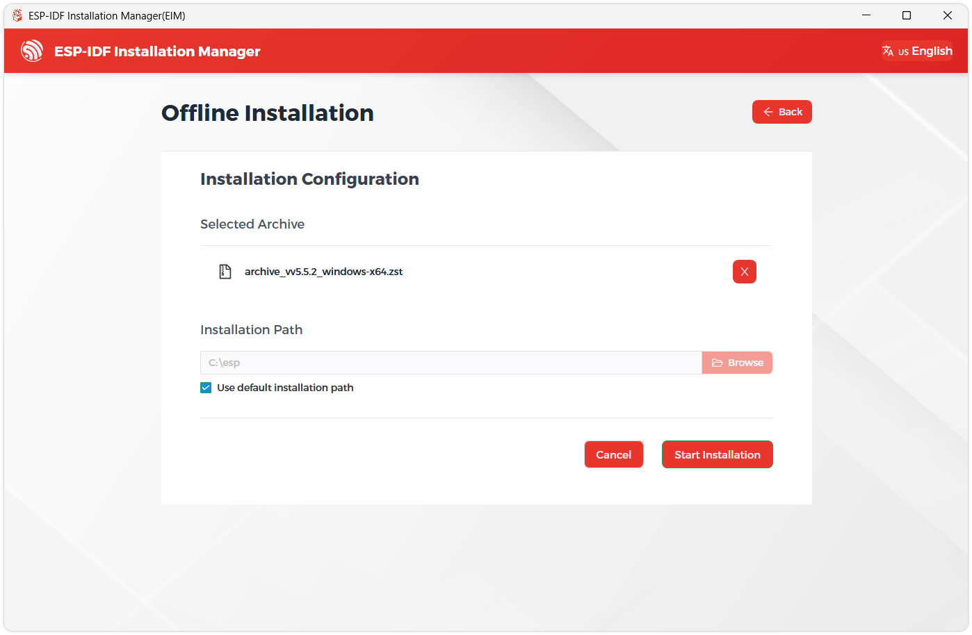
Next, select the installation path. We recommend using the default path. If you need to customize it, ensure the path does not contain Chinese characters or spaces. Click Start installation to proceed.
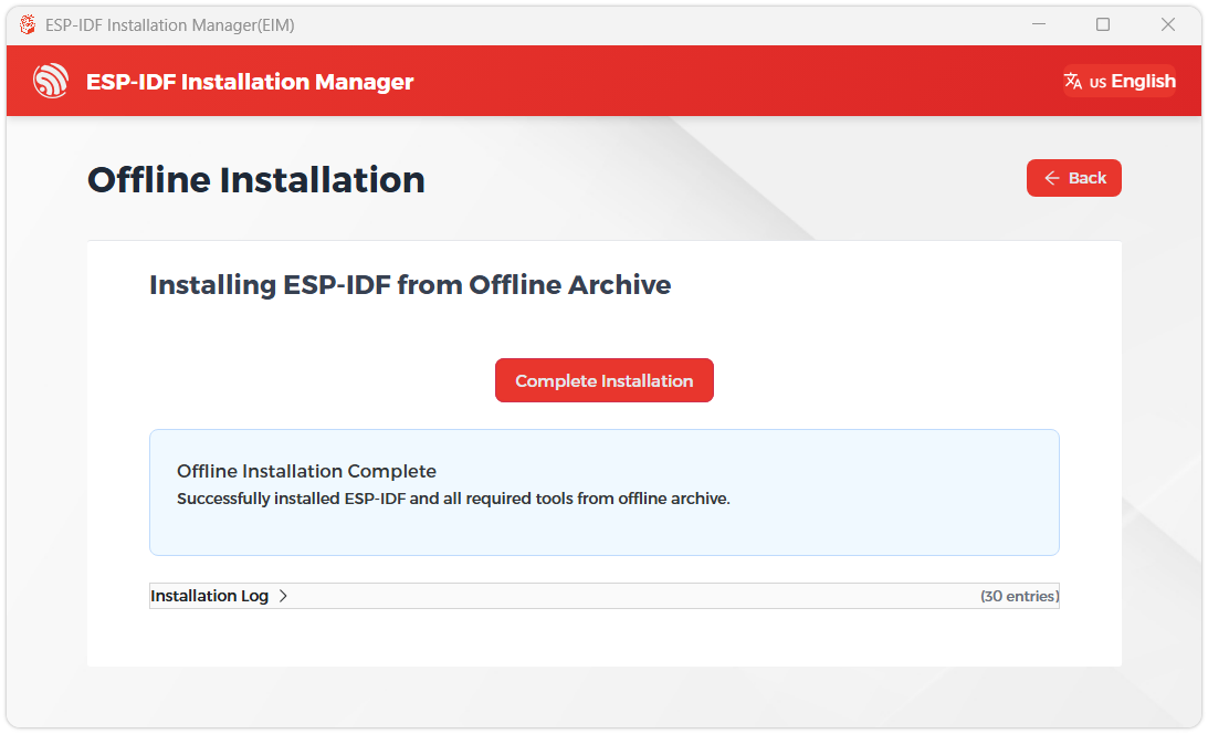
When you see the following screen, the ESP-IDF installation is successful.
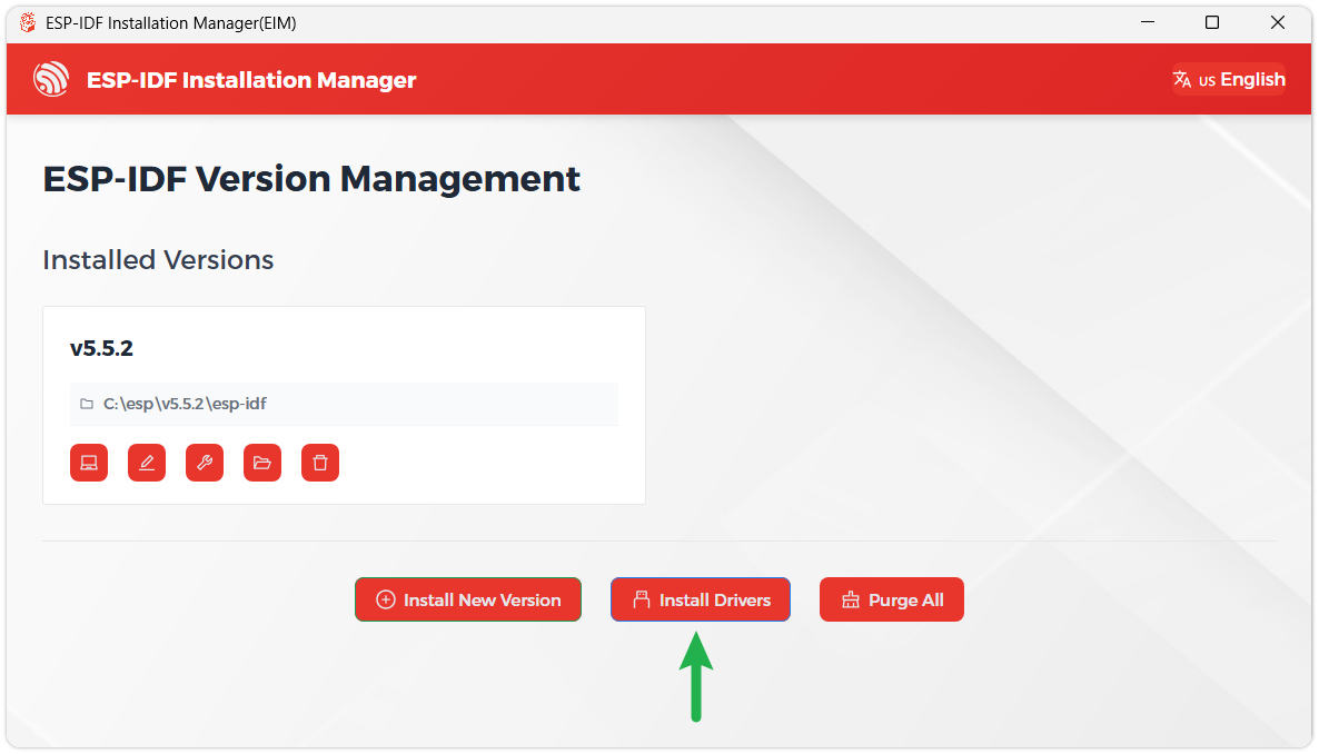
We recommend installing the drivers as well. Click Finish installation, then select Install driver.
Install Visual Studio Code and the ESP-IDF Extension
Download and install Visual Studio Code.
During installation, it is recommended to check Add "Open with Code" action to Windows Explorer file context menu to facilitate opening project folders quickly.
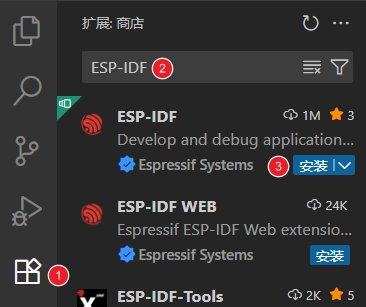
In VS Code, click the Extensions icon
 in the Activity Bar on the side (or use the shortcut Ctrl + Shift + X) to open the Extensions view.
Enter ESP-IDF in the search box, locate the ESP-IDF extension, and click Install.
For ESP-IDF extension versions ≥ 2.0, the extension will automatically detect and recognize the ESP-IDF environment installed in the previous steps, requiring no manual configuration.
Demo
The ESP-IDF demos are located in the ESP-IDF directory of the demo package.
| Demo | Basic Program Description | Dependency Library |
|---|---|---|
| 01_ADC_Test | Get the voltage value of the lithium battery | - |
| 02_WIFI_AP | Set to AP mode to obtain the IP address of the access device | - |
| 03_WIFI_STA | Set to STA mode to connect to Wi-Fi and obtain an IP address | - |
| 04_Audio_Test | Play the sound recorded by the microphone through the speaker | LVGL V9.5.0 |
| 05_LVGL_V8_Test | LVGLV8 demo | LVGL V8.3.11 |
| 06_LVGL_V9_Test | LVGLV9 demo | LVGL V9.5.0 |
| 07_FactoryProgram | Comprehensive demo | LVGL V9.5.0 |
01_ADC_Test
Demo Description
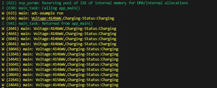
- The analog voltage connected through the GPIO is converted to digital by the ADC, and then the actual lithium battery voltage is calculated and printed to the terminal.
Hardware Connection
- Connect the board to the computer using a USB cable
Code Analysis
printf("adc-example run\n");             // Terminal output information
bsp_batt_init();                         // Initialize ADC channel
xTaskCreate(Batt_LoopTask, "Batt_LoopTask", 4 * 1024, NULL, 3, NULL); // Create a task to obtain voltage and battery charging information
Operation Result
After the program is compiled and uploaded, open the serial monitor to see the printed output of the lithium battery voltage and charging information, as shown in the following figure:
02_WIFI_AP
Demo Description
- This demo can set the development board as a hotspot, allowing phones or other devices in STA mode to connect to the development board.
Hardware Connection
- Connect the board to the computer using a USB cable
Code Analysis
In the file
softap_example_main.c, findSSIDandPASSWORD, and then your phone or other device in STA mode can use the SSID and PASSWORD to connect to the development board.#define EXAMPLE_ESP_WIFI_SSID "waveshare_esp32"#define EXAMPLE_ESP_WIFI_PASSWORD "wav123456"
Operation Result
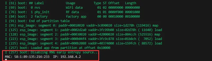
After flashing the program, open the Serial Terminal. If a device successfully connects to the hotspot, it will output the device's MAC address and IP address, as shown in the figure:
03_WIFI_STA
Demo Description
- This example configures the development board as a STA device to connect to a router, thereby accessing the system network.
Hardware Connection
- Connect the board to the computer using a USB cable
Code Analysis
In the file
esp_wifi_bsp.c, findssidandpassword, then modify them to the SSID and Password of an available router in your current environment.wifi_config_t wifi_config = {.sta = {.ssid = "PDCN",.password = "1234567890",},};
Operation Result
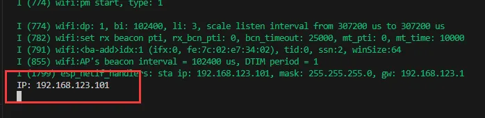
After flashing the program, open the Serial Terminal. If the device successfully connects to the hotspot, the obtained IP address will be output, as shown in the figure:
04_Audio_Test
Demo Description
- Demonstrate how to acquire microphone data, play music, and other functions.
Hardware Connection
- Connect the board to the computer using a USB cable
Code Analysis
bsp_broolesia_display_init();                             // Screen initialization
speaker = bsp_audio_codec_speaker_init();                 // Obtain playback handle
microphone = bsp_audio_codec_microphone_init();           // Obtain recording handle
boot_button_ = new Button(BUTTON_0_GPIO_PIN);Instantiate button
InitializeButtons();                                      // Button callback initialization
ESP_ERROR_CHECK(esp_codec_dev_open(speaker, &fs));        // Open playback
ESP_ERROR_CHECK(esp_codec_dev_open(microphone, &fs));     // Open recording
ESP_ERROR_CHECK(esp_codec_dev_set_out_vol(speaker, 100)); // Set playback volume
ESP_ERROR_CHECK(esp_codec_dev_set_in_gain(microphone,35));// Set recording gain
Operation Result
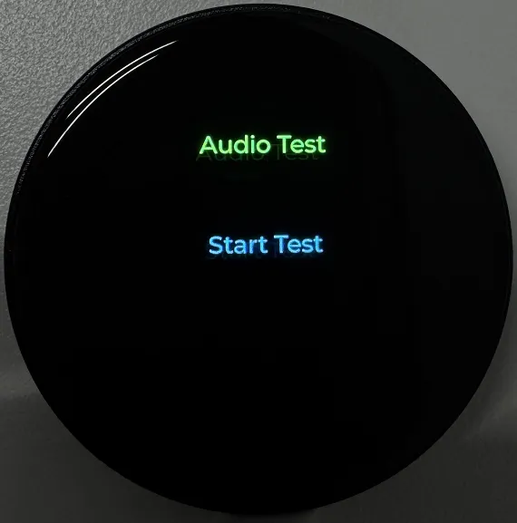
After the program is flashed, the screen displays as shown:
TIP- Press the BOOT button once to record for 3 seconds; after recording ends, the recording is played back automatically.
- Double-click the BOOT button to play a piece of music; press and hold the BOOT button to interrupt playback.
05_LVGL_V8_Test
Demo Description
- Implements various multifunctional GUI interfaces on the screen by porting LVGL V8.
Hardware Connection
- Connect the board to the computer using a USB cable
Code Analysis
#define BACKLIGHT_EN 1               // Macro definition, enable backlight test, enabled by default
bsp_broolesia_display_init();        // Initialize screen and LVGL
if(bsp_display_lock(-1) == ESP_OK) { // Wait for lock
  lv_demo_widgets();                 // LVGL default UI
  bsp_display_unlock();              // Release lock
}
Operation Result
After the program is flashed, the device operation result is as follows:

06_LVGL_V9_Test
Demo Description
- Implements various multifunctional GUI interfaces on the screen by porting LVGL V9.
Hardware Connection
- Connect the board to the computer using a USB cable
Code Analysis
#define BACKLIGHT_EN 1               // Macro definition, enable backlight test, enabled by default
bsp_broolesia_display_init();        // Initialize screen and LVGL
if(bsp_display_lock(-1) == ESP_OK) { // Wait for lock
  lv_demo_widgets();                 // LVGL default UI
  bsp_display_unlock();              // Release lock
}
Operation Result
After the program is flashed, the device operation result is as follows:
07_FactoryProgram
Demo Description
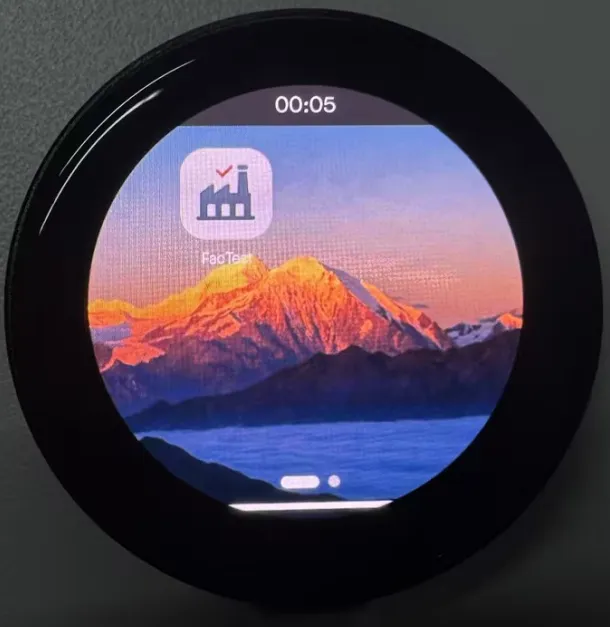
- Factory firmware. Users can flash the provided factory firmware to quickly get to know the development board.
Hardware Connection
- Connect the board to the computer using a USB cable
Operation Result
After flashing the factory firmware and restarting, the display on the development board will appear as shown below:
Resources
1. Hardware Resources
Development Board Design Files
2. Technical Manuals
ESP32-S3 Chip Official Manuals
Datasheets
3. Demo
Support
Monday-Friday (9:30-6:30) Saturday (9:30-5:30)
Email: services01@spotpear.com
[Tutorial Navigation]
- Features
- Onboard Resources
- Interface Introduction
- AMOLED Display Specifications
- Dimensions
- Working with Arduino
- Arduino Getting Started
- Setting Up Development Environment
- 1. Installing and Configuring Arduino IDE
- 2. Installing Libraries
- 3. Arduino Project Parameter Settings
- Demo
- ESP-IDF
- Resources
- Support