




- sales/support
Google Chat:---
- sales
+86-0755-88291180
- sales01
sales@spotpear.com
- sales02
dragon_manager@163.com
- support
tech-support@spotpear.com
- CEO-Complaints
zhoujie@spotpear.com
- Only Tech-Support
WhatsApp:13246739196
- Purchase/Shipping/Refund
WhatsApp:13424403025
- HOME
- >
- ARTICLES
- >
- Common Moudle
- >
- ESP
ESP32-P4-WIFI6-DB User Guide
Features
- Processor
- Equipped with a RISC-V 32-bit dual-core processor (HP system), with DSP and instruction set extensions and a floating-point unit (FPU), running at up to 360 MHz
- Equipped with a RISC-V 32-bit single-core processor (LP system), running at up to 40 MHz
- Equipped with an ESP32-C5 Wi-Fi / Bluetooth co-processor, expanding dual-band Wi-Fi 6 and Bluetooth 5 (LE) functionality via SDIO
- Memory
- 128 KB high-performance (HP) system read-only memory (ROM)
- 16 KB low-power (LP) system read-only memory (ROM)
- 768 KB high-performance (HP) L2 memory (L2MEM)
- 32 KB low-power (LP) SRAM
- 8 KB system tightly coupled memory (TCM)
- 32 MB PSRAM packaged in the chip, and 32 MB onboard Nor Flash
- Peripheral Interfaces
- 2 × 20 pin headers onboard, exposing 27 remaining programmable GPIOs
- Onboard speaker connector and microphone; audio capture and playback can be implemented using the codec chip and amplifier chip
- Onboard MIPI-CSI HD camera interface, supporting Full HD 1080P image capture and encoding; integrated image signal processor (ISP) and H.264 video encoder, supporting H.264 and JPEG video encoding (1080P @30fps), suitable for computer vision, machine vision, and other fields
- Onboard MIPI-DSI HD display interface, integrated pixel processing accelerator (PPA) and 2D graphics acceleration controller (2D DMA), supporting JPEG image decoding (1080P @30fps), suitable for smart home control panels, industrial control panels, vending machines, and other scenarios
Onboard Resources
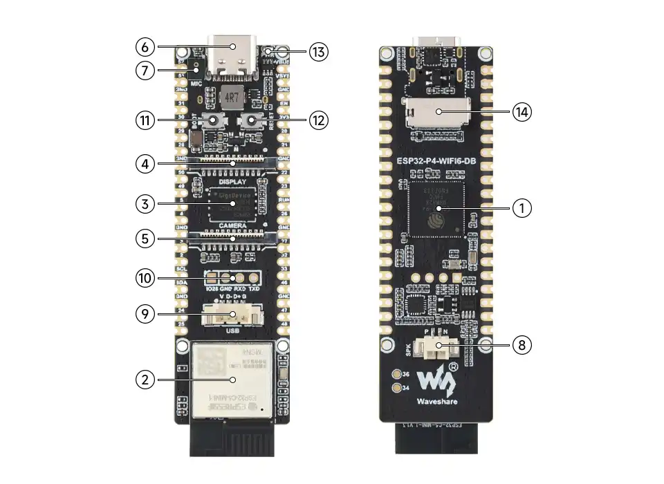
- ESP32-P4NRW32X: ESP32-P4 with 32 MB PSRAM packaged in the chip.
- ESP32-C5 Module: Communicates with the ESP32-P4 via an SDIO interface, providing 2.4 GHz / 5 GHz dual-band Wi-Fi 6 and Bluetooth 5 (LE).
- 32 MB Nor Flash.
- Display Interface: MIPI-DSI, 2‑lane. Compatible with
5/7/8/10.1-inch DSI screens. - Camera Interface: MIPI-CSI, 2‑lane. Compatible with cameras such as the
OV5647. - Type-C Port: For power supply, program flashing, and serial debugging.
- Microphone: Onboard audio capture.
- Speaker Connector: MX1.25 2P connector, supports 8 Ω 2 W speakers.
- 4PIN USB Interface: USB OTG 2.0 High-Speed interface.
- Wireless Module UART Pads: Exposes the serial port of the wireless co-processor.
- BOOT Button: Press during power‑on or reset to enter download mode.
- RESET Button: Resets the board.
- PWR: Power indicator.
- TF Card Slot: SDIO 3.0 interface protocol.
Peripheral Quick Reference
| Module | Device / Function | Interface | Address / Parameters | GPIO / Signals |
|---|---|---|---|---|
| LCD | MIPI-DSI display | MIPI-DSI | 2‑lane; supports 5 / 7 / 8 / 10.1‑inch panel configurations | LCD reset not connected; backlight controlled via shared I2C |
| Touch | GT911 capacitive touch | I2C | 7‑bit address 0x5D / 0x14 | SDA=GPIO7, SCL=GPIO8; RST / INT not connected |
| LCD Backlight | Backlight controller | I2C | 7‑bit address 0x45; brightness register 0x96 | SDA=GPIO7, SCL=GPIO8 |
| Camera | MIPI-CSI camera interface | MIPI-CSI + SCCB | 2‑lane; camera model and address depend on module documentation | SCCB shared on GPIO7 / GPIO8; XCLK / RESET not connected |
| Audio | ES8311 Codec | I2C + I2S | 7‑bit I2C address 0x18; 8‑bit write address 0x30; single analog microphone | I2C: SDA=GPIO7, SCL=GPIO8; MCLK=GPIO13, SCLK=GPIO12, WS=GPIO10, DOUT=GPIO9, DIN=GPIO11 |
| Amplifier Control | Onboard speaker amp enable | GPIO | High level to enable | GPIO53 |
| TF Card | SDMMC 4‑bit | SDMMC | 4‑bit mode | CLK=GPIO43, CMD=GPIO44, D0=GPIO39, D1=GPIO40, D2=GPIO41, D3=GPIO42; power control=GPIO45 |
| ESP32-C5 | ESP-Hosted communication | SDIO | Wi‑Fi 6 / Bluetooth 5 (LE) co‑processor | CLK=GPIO18, CMD=GPIO19, D0=GPIO14, D1=GPIO15, D2=GPIO16, D3=GPIO17, RESET=GPIO54 |
Pin Definitions
When using the GPIO headers on the ESP32-P4-WIFI6-DB, note the multiplexed functions marked on the pin diagram. Some GPIOs are already connected to onboard peripherals; before using them as general‑purpose I/O, confirm that the corresponding peripheral is not enabled.
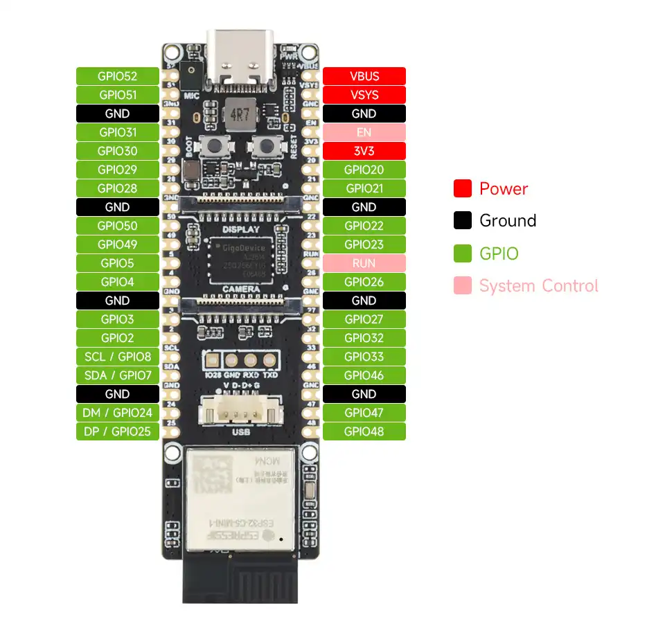
GPIO Allocation
The table below lists the GPIOs already occupied by onboard circuits and those brought out to expansion headers.
| GPIO | Signal Name | Connected To | Remarks |
|---|---|---|---|
| GPIO0 | GPIO0 | XTAL_32K_N | XTAL_32K |
| GPIO1 | GPIO1 | XTAL_32K_P | XTAL_32K |
| GPIO2 | GPIO2 | Reserved pad / pin header | Expansion header GPIO2 |
| GPIO3 | GPIO3 | Reserved pad / pin header | Expansion header GPIO3 |
| GPIO4 | GPIO4 | Reserved pad / pin header | Expansion header GPIO4 |
| GPIO5 | GPIO5 | Reserved pad / pin header | Expansion header GPIO5 |
| GPIO6 | GPIO6 | ESP32-C5 module | |
| GPIO7 | I2C SDA | ES8311, GT911, LCD backlight, camera SCCB, expansion header | Shared I2C SDA |
| GPIO8 | I2C SCL | ES8311, GT911, LCD backlight, camera SCCB, expansion header | Shared I2C SCL |
| GPIO9 | I2S DOUT | ES8311 DSDIN | Audio playback data |
| GPIO10 | I2S WS | ES8311 LRCK | Audio frame sync |
| GPIO11 | I2S DIN | ES8311 ASDOUT | Audio capture data |
| GPIO12 | I2S SCLK | ES8311 SCLK | Audio bit clock |
| GPIO13 | I2S MCLK | ES8311 MCLK | Audio master clock |
| GPIO14 | GPIO14 | ESP32-C5 module | C5 SDIO D0 |
| GPIO15 | GPIO15 | ESP32-C5 module | C5 SDIO D1 |
| GPIO16 | GPIO16 | ESP32-C5 module | C5 SDIO D2 |
| GPIO17 | GPIO17 | ESP32-C5 module | C5 SDIO D3 |
| GPIO18 | GPIO18 | ESP32-C5 module | C5 SDIO CLK |
| GPIO19 | GPIO19 | ESP32-C5 module | C5 SDIO CMD |
| GPIO20 | GPIO20 | Reserved pad / pin header | Expansion header GPIO20 |
| GPIO21 | GPIO21 | Reserved pad / pin header | Expansion header GPIO21 |
| GPIO22 | GPIO22 | Reserved pad / pin header | Expansion header GPIO22 |
| GPIO23 | GPIO23 | Reserved pad / pin header | Expansion header GPIO23 |
| GPIO24 | GPIO24 | Reserved pad / pin header | GPIO24 / USB1P1_N0 |
| GPIO25 | GPIO25 | Reserved pad / pin header | GPIO25 / USB1P1_P0 |
| GPIO26 | GPIO26 | Reserved pad / pin header | GPIO26 / USB1P1_N1 |
| GPIO27 | GPIO27 | Reserved pad / pin header | GPIO27 / USB1P1_P1 |
| GPIO28 | GPIO28 | Reserved pad / pin header | Expansion header GPIO28 |
| GPIO29 | GPIO29 | Reserved pad / pin header | Expansion header GPIO29 |
| GPIO30 | GPIO30 | Reserved pad / pin header | Expansion header GPIO30 |
| GPIO31 | GPIO31 | Reserved pad / pin header | Expansion header GPIO31 |
| GPIO32 | GPIO32 | Reserved pad / pin header | Expansion header GPIO32 |
| GPIO33 | GPIO33 | Reserved pad / pin header | Expansion header GPIO33 |
| GPIO34 | GPIO34 | Solder pad | Strapping pin |
| GPIO35 | GPIO35 | BOOT key | Strapping pin |
| GPIO36 | GPIO36 | Solder pad | Strapping pin; external 3.3 V pull-up |
| GPIO37 | UART0_TXD | CH343P | UART0 TX; not recommended for general-purpose use |
| GPIO38 | UART0_RXD | CH343P | UART0 RX; not recommended for general-purpose use |
| GPIO39 | SD_D0 | TF card | SDMMC 4-bit data line |
| GPIO40 | SD_D1 | TF card | SDMMC 4-bit data line |
| GPIO41 | SD_D2 | TF card | SDMMC 4-bit data line |
| GPIO42 | SD_D3 | TF card | SDMMC 4-bit data line |
| GPIO43 | SD_CLK | TF card | SDMMC clock line |
| GPIO44 | SD_CMD | TF card | SDMMC command line |
| GPIO45 | SD_VDD_EN | TF card power control | Low to enable |
| GPIO46 | GPIO46 | Reserved pad / pin header | Expansion header GPIO46 |
| GPIO47 | GPIO47 | Reserved pad / pin header | Expansion header GPIO47 |
| GPIO48 | GPIO48 | Reserved pad / pin header | Expansion header GPIO48 |
| GPIO49 | GPIO49 | Reserved pad / pin header | Expansion header GPIO49 |
| GPIO50 | GPIO50 | Reserved pad / pin header | Expansion header GPIO50 |
| GPIO51 | GPIO51 | Reserved pad / pin header | Expansion header GPIO51 |
| GPIO52 | GPIO52 | Reserved pad / pin header | Expansion header GPIO52 |
| GPIO53 | PA_CTRL | NS4150B CTRL | Amplifier enable, active high |
| GPIO54 | C5_CHIP_PU | ESP32-C5 enable | High to enable, low to reset |
LCD and Touch Pins
| Signal | GPIO / Signal | Description |
|---|---|---|
MIPI-DSI | MIPI interface | 2‑lane display interface |
LCD_RST | Not connected | No dedicated GPIO for LCD reset |
LCD_BL | I2C 0x45 | Backlight controlled via register 0x96 |
TP_SCL | GPIO8 | GT911 touch I2C SCL, shared bus |
TP_SDA | GPIO7 | GT911 touch I2C SDA, shared bus |
TP_RST | Not connected | GT911 reset signal not connected |
TP_INT | Not connected | GT911 interrupt signal not connected; uses polling mode |
Audio and TF Card
| Signal / Peripheral | GPIO / Signal | Description |
|---|---|---|
I2S_MCLK | GPIO13 | ES8311 master clock |
I2S_SCLK | GPIO12 | ES8311 bit clock |
I2S_WS | GPIO10 | ES8311 frame sync |
I2S_DOUT | GPIO9 | ESP32-P4 output to ES8311 |
I2S_DIN | GPIO11 | ES8311 output to ESP32-P4 |
| Amplifier enable | GPIO53 | Active high |
SD_D0 / SD_D1 | GPIO39 / GPIO40 | SDMMC data lines |
SD_D2 / SD_D3 | GPIO41 / GPIO42 | SDMMC data lines |
SD_CLK / SD_CMD | GPIO43 / GPIO44 | SDMMC clock and command lines |
SD_VDD_EN | GPIO45 | TF card power control, low to enable |
I2C Device Summary
| Device | Model / Function | I2C Address | I2C Pins | Notes |
|---|---|---|---|---|
| Audio Codec | ES8311 | 7‑bit 0x18; 8‑bit write address 0x30 | GPIO7 / GPIO8 | Onboard audio capture and playback |
| Touch | GT911 | 0x5D / 0x14 | GPIO7 / GPIO8 | Both addresses are tried; RST / INT not connected |
| LCD Backlight | Backlight controller | 0x45 | GPIO7 / GPIO8 | Brightness register is 0x96 |
| Camera SCCB | External camera module | Depends on module | GPIO7 / GPIO8 | Shares bus with onboard I2C devices |
Precautions
- GPIO7 / GPIO8 are the onboard shared I2C bus. When connecting external I2C devices, confirm that the addresses do not conflict.
- GPIO45 is used for TF card power control, GPIO53 for the audio amplifier, and GPIO54 for ESP32-C5 communication reset; it is not recommended to use these as general‑purpose GPIO while the corresponding peripherals are active.
- The LCD reset, GT911 reset, and interrupt signals are not connected; the corresponding control is handled through software in the display or touch drivers.
Dimensions
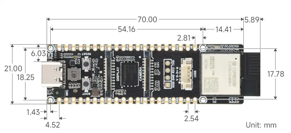
Working with Arduino
This chapter includes the following sections, please read as needed:
- Arduino Getting Started
- Setting Up the Arduino Development Environment
- Arduino Examples
- Board Resources and Shared Interfaces
The Arduino examples for the ESP32-P4-WIFI6-DB are based on Arduino-ESP32 3.3.11. The onboard ESP32-P4 is the compile target for Arduino projects. The ESP32-C5 wireless co-processor connects to the ESP32-P4 via ESP-Hosted/SDIO and is not a compile target for Arduino projects.
Before running the display, camera, audio, or TF card examples, connect the corresponding onboard or external hardware first, and install the required libraries and configuration files as described in the example prerequisites.
Arduino Getting Started
New to Arduino ESP32 development and looking for a quick start? We have prepared a comprehensive Getting Started Tutorial for you.
- Section 0: Getting to Know ESP32
- Section 1: Installing and Configuring Arduino IDE
- Section 2: Arduino Basics
- Section 3: Digital Output/Input
- Section 4: Analog Input
- Section 5: Pulse Width Modulation (PWM)
- Section 6: Serial Communication (UART)
- Section 7: I2C Communication
- Section 8: SPI Communication
- Section 9: Wi-Fi Basics
- Section 10: Web Server
- Section 11: Bluetooth
- Section 12: LVGL GUI Development
- Section 13: Comprehensive Project
Note: This tutorial uses the ESP32-S3-Zero as a reference example, and all hardware code is based on its pinout. Before you start, we recommend checking the pinout of your development board to ensure the pin configuration is correct.
Setting Up the Arduino Development Environment
1. Install Arduino IDE
Please refer to the Install and Configure Arduino IDE Tutorial to install the Arduino IDE and add ESP32 board support.
2. Install Arduino-ESP32 and Board Definitions
- Install Arduino-ESP32
3.3.11. The example code and board definitions are organized around this version. Do not mix the board files in this directory with other versions. - Copy
examples/Arduino/esp32/variants/waveshare_esp32_p4_wifi6_dbfrom the example package to thevariantsdirectory in your Arduino-ESP32 installation. examples/Arduino/esp32/boards.txtis a completeboards.txtsnapshot based on Arduino-ESP323.3.11. If your Arduino-ESP32 installation has no other local board modifications, you can back up the original file and replace it. If you have already added other boards, merge only the entries beginning withwaveshare_esp32_p4_wifi6_db..- Restart Arduino IDE and select
Waveshare ESP32-P4-WIFI6-DBfrom the board list.
The Arduino examples are located in the examples/Arduino directory of the ESP32-P4-WIFI6-DB example repository.
3. Arduino IDE Tool Options
After connecting the board, select the board and port from the "Tools" menu in Arduino IDE. The default parameters in the board definition are as follows:
| Option | Setting |
|---|---|
| Board | Waveshare ESP32-P4-WIFI6-DB |
| Compile Target | esp32p4 |
| Flash Size | 32MB |
| Partition Scheme | 32M Flash (13MB APP/6.75MB SPIFFS) |
| PSRAM | The board entry automatically defines BOARD_HAS_PSRAM |
| Upload Mode | UART0 |
| Serial Monitor Baud Rate | 115200 |
The development board uses the onboard CH343P USB-to-serial chip for program flashing and serial log output. Keep the upload mode at the default UART0. When changing the partition scheme or upload speed, confirm the corresponding example's memory requirements and actual connection. The serial output for all examples uses 115200.
Arduino Examples
The example directory is examples/Arduino and currently includes the following examples:
| Example Directory | Function | Main Dependencies or Hardware |
|---|---|---|
board_check | Outputs chip, Flash, PSRAM, and heap memory information | No external peripherals required |
gpio | Interactive GPIO testing via serial commands | Arduino-ESP32 Console |
i2c | Scans for 7‑bit addresses on the I2C1 bus | Wire1, I2C1 |
i2s | Audio loopback from a single microphone to a single speaker using ES8311 | ES8311, onboard mic and speaker |
sdmmc | Tests TF file read/write in 4‑bit mode | Onboard TF card |
mipi_dsi | Displays MIPI-DSI color bars and tests backlight | LCD panel, backlight controller |
mipi_csi | Displays OV5647 camera feed on the MIPI-DSI LCD | OV5647, LCD, ESP_Video |
board_check: Board Information Check
Open board_check/board_check.ino, compile and upload, then set the serial monitor to 115200. The example will output:
- Chip model and chip revision;
- CPU core count and frequency;
- Flash size;
- PSRAM size;
- Remaining heap memory.
This example does not access the LCD, camera, audio, SDMMC, or ESP-Hosted, making it suitable for first confirming that the Arduino board definition is working correctly.
gpio: GPIO Console
Open gpio/gpio.ino and upload it. Set the serial monitor line ending to Newline. Enter help to see the command list.
gpio read <pin>
gpio write <pin> <0|1>
gpio mode <pin> <in|out|in_pu|in_pd>
For example:
gpio mode 2 out
gpio write 2 0
gpio write 2 1
gpio mode 4 in_pu
gpio read 4
This board variant does not define an onboard LED_BUILTIN. When testing GPIO, avoid using pins that are already occupied by the MIPI display, touch controller, camera, SDMMC, ESP-Hosted/SDIO, or audio codec.
i2c: I2C Address Scan
Open i2c/i2c.ino and upload it. The example uses Arduino Wire1 to scan the I2C1 bus. The default parameters are:
| Item | Parameter |
|---|---|
| SDA | GPIO7 |
| SCL | GPIO8 |
| Frequency | 400 kHz |
| Address Format | 7‑bit I2C address |
This bus is shared by devices such as the ES8311, LCD backlight controller, GT911, and camera SCCB. Do not run other examples that initialize I2C1 at the same time as this scan. If no device responds, the program will not list it as a device; this does not indicate an issue with the scanning program.
i2s: ES8311 Audio Loopback
Open i2s/i2s.ino and upload it. This runs a mono audio loopback using the onboard microphone and speaker. The example runs at 48 kHz, 16-bit, I2S standard mono mode using the left-channel slot.
| Signal | GPIO |
|---|---|
| MCLK | GPIO13 |
| BCLK | GPIO12 |
| LRCK | GPIO10 |
| DOUT | GPIO9 |
| DIN | GPIO11 |
| Amplifier Enable | GPIO53, high to enable |
The ES8311 Arduino Wire1 control address is the 7‑bit address 0x18. If the serial output does not show ES8311 ready, or if there is no sound in the loopback, check the I2C address, MCLK, amplifier enable, and the microphone and speaker connections. Acoustic feedback (howling) may occur if the microphone and speaker are too close together.
sdmmc: TF File Read/Write
Insert a TF card, then open sdmmc/sdmmc.ino and upload it. The example mounts the card using the 4-bit SDMMC interface, reads the capacity, and performs write and read tests on the /arduino_test.txt file in the root directory.
| Signal | GPIO |
|---|---|
| CLK | GPIO43 |
| CMD | GPIO44 |
| D0-D3 | GPIO39, GPIO40, GPIO41, GPIO42 |
| Card Power Control | GPIO45, low to enable |
If mounting fails, check that the TF card is inserted, the format is recognized, and the SDMMC pins are not occupied by other examples.
mipi_dsi: MIPI-DSI LCD
mipi_dsi uses a project-local LCD driver to initialize the MIPI-DSI panel, cyclically displays horizontal and vertical color bars, and verifies the LCD backlight through the I2C backlight controller.
Before running, install or confirm the following libraries and versions:
| Library | Version |
|---|---|
ESP32_Display_Panel | 1.0.4 |
ESP32_IO_Expander | 1.1.1 |
esp-lib-utils | 0.2.3 |
In mipi_dsi/esp_panel_drivers_conf.h, select only one local LCD driver:
ESP_PANEL_DRIVERS_LCD_ENABLE_JD9365_LOCALESP_PANEL_DRIVERS_LCD_ENABLE_HX8394_LOCALESP_PANEL_DRIVERS_LCD_ENABLE_ILI9881C_LOCAL
The current default configuration is for the 10.1inch JD9365, with 800 × 1280 resolution, RGB565, and dual DSI lanes. When using a different LCD panel, you must select the controller and configuration that match the actual panel.
mipi_csi: Camera Display
mipi_csi initializes the OV5647 MIPI-CSI camera and the MIPI-DSI LCD, and displays the camera's live feed on the LCD. The LCD interface supports JD9365, HX8394, and ILI9881C. mipi_csi/lcd_panel.h currently defaults to the 10.1inch JD9365 configuration.
Before running, ensure the following prerequisites are met:
- Use Arduino-ESP32
3.3.11and its corresponding ESP32-P4 precompiled libraries. - Confirm that
ESP_Videohas the MIPI-CSI video device enabled:CONFIG_ESP_VIDEO_ENABLE_MIPI_CSI_VIDEO_DEVICE=y. - In
lcd_panel.h, setLCD_PANEL_TYPEto match the actual connected LCD panel type. - Connect the OV5647 camera and the actual LCD panel, and verify that camera power, MIPI cables, and the shared I2C/SCCB connections are correct.
mipi_csi, mipi_dsi, i2s, and i2c do not all initialize I2C1 in the same way: i2s and i2c use Arduino Wire1, mipi_dsi uses the legacy I2C API, and mipi_csi uses the newer i2c_master API. Do not run these examples simultaneously in the same Arduino project, or re-initialize the same bus repeatedly.
Board Resources and Shared Interfaces
Pin Aliases
The Arduino board variant provides the following common pin aliases:
| Interface | Pin |
|---|---|
SDA / SDA1 | GPIO7 |
SCL / SCL1 | GPIO8 |
SS | GPIO26 |
MOSI | GPIO32 |
MISO | GPIO33 |
SCK | GPIO36 |
UART TX / RX | GPIO37 / GPIO38 |
GPIO7 and GPIO8 are the onboard I2C1 shared bus. The LCD backlight, GT911, ES8311, and camera SCCB all use the relevant board-level bus resources. Before changing pins, check both the actual hardware connections and the initialization code in the corresponding examples.
I2C and Onboard Peripherals
The board uses GPIO7 (SDA) and GPIO8 (SCL) to connect multiple I2C devices, with a default frequency of 400 kHz. Different examples use different I2C APIs:
i2candi2suse ArduinoWire1.mipi_dsiuses the legacy API fromdriver/i2c.hto control the LCD backlight.mipi_csiusesWire1to create a new‑stylei2c_masterbus, and passes the bus handle to the camera SCCB and LCD backlight.
Do not mix the initialization methods from these examples within the same program. The build results and hardware state for complex examples must be verified individually on the target board; the current configuration cannot be applied directly after changes to the Arduino-ESP32 version, LCD panel model, or hardware connections.
Working with ESP-IDF
This chapter includes the following sections:
ESP-IDF Getting Started
New to ESP32 ESP-IDF development and looking to get started quickly? We have prepared a general Getting Started Tutorial for you.
- Section 1: Environment Setup
- Section 2: Running Examples
- Section 3: Creating a Project
- Section 4: Using Components
- Section 5: Debugging
- Section 6: FreeRTOS
- Section 7: Peripherals
- Section 8: Wi-Fi Programming
- Section 9: BLE Programming
Please Note: This tutorial uses the ESP32-S3-Zero as a teaching example, and all hardware code is based on its pinout. Before you start, it is recommended that you check the pinout of your development board to ensure the pin configuration is correct.
Setting Up the ESP-IDF Development Environment
The ESP-IDF BSP and brookesia_test in the ESP32-P4-WIFI6-DB repository require ESP-IDF >=5.5, and 10_wifi_antenna_tesat requires ESP-IDF >=6.0. These are the version constraints declared in the component manifest. Dependent components may impose additional requirements. For the component and configuration requirements of specific examples, refer to the README in the corresponding example directory.
The following guide uses Windows as an example, demonstrating development using VS Code + the ESP-IDF extension. macOS and Linux users should refer to the official documentation.
The screenshots in this section use ESP-IDF V5.5.2 as an example. When installing, please select the ESP-IDF version that matches your board's example.
Install the ESP-IDF Development Environment
Download the installation manager from the ESP-IDF Installation Manager page. This is Espressif's latest cross-platform installer. The following steps demonstrate how to use its offline installation feature.
Click the Offline Installer tab on the page, then select Windows as the operating system and the ESP-IDF version you need (the version shown in the screenshot is for reference only — choose the version that fits your actual needs).
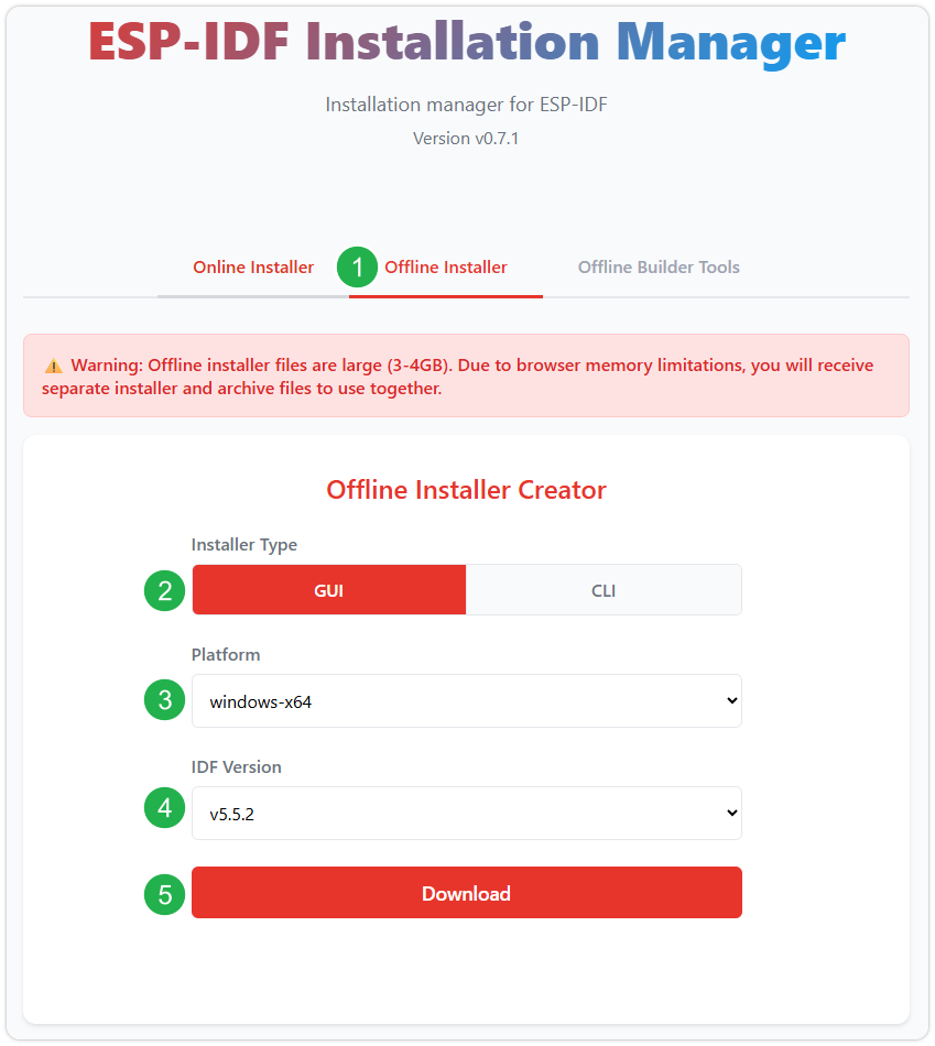
After confirming your selection, click the download button. The browser will automatically download two files: the ESP-IDF Offline Package (.zst) and the ESP-IDF Installer (.exe).
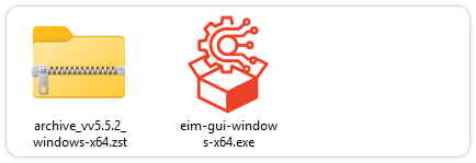
Please wait for both files to finish downloading.
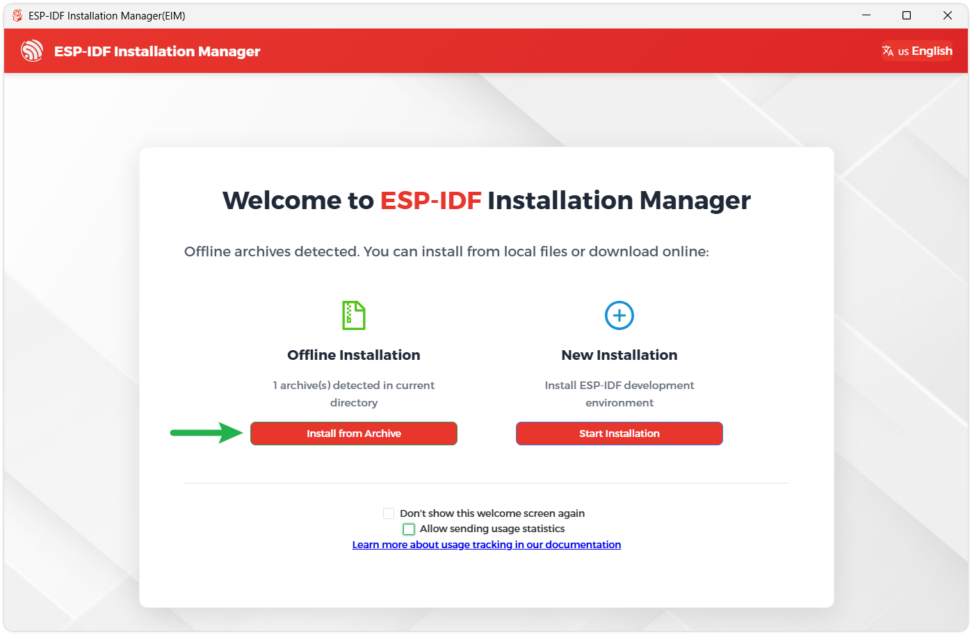
Once the download is complete, double-click to run the ESP-IDF Installer (eim-gui-windows-x64.exe).
The installer will automatically detect if the offline package exists in the same directory. Click Install from archive.
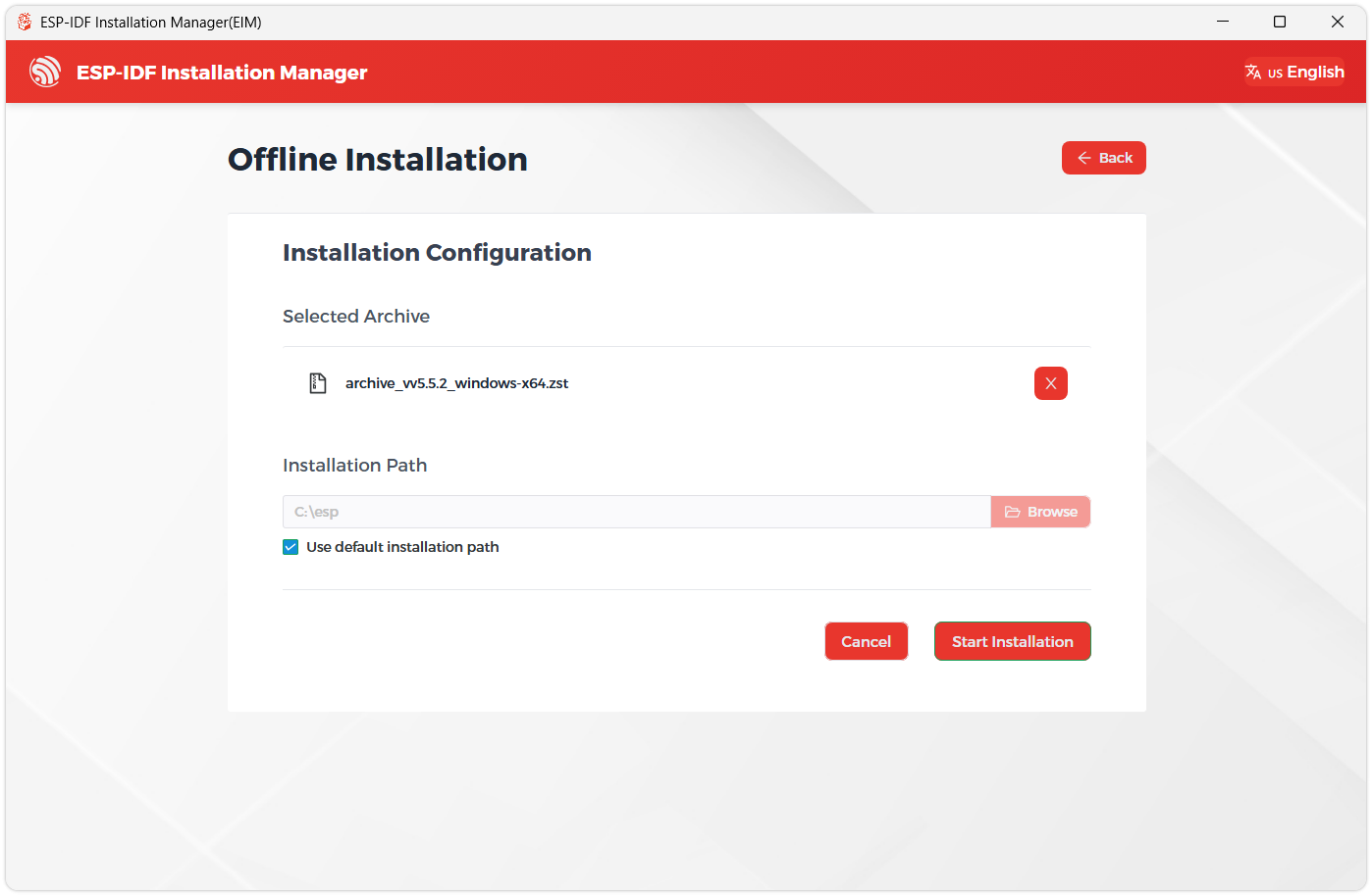
Next, select the installation path. We recommend using the default path. If you need to customize it, ensure the path does not contain Chinese characters or spaces. Click Start installation to proceed.
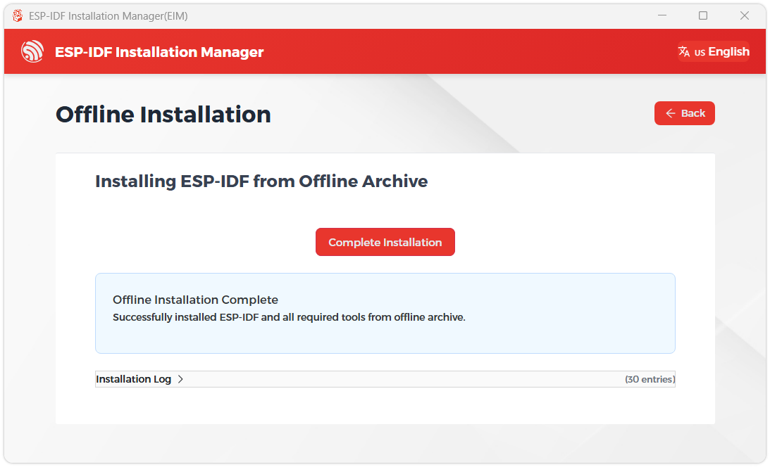
When you see the following screen, the ESP-IDF installation is successful.
We recommend installing the drivers as well. Click Finish installation, then select Install driver.
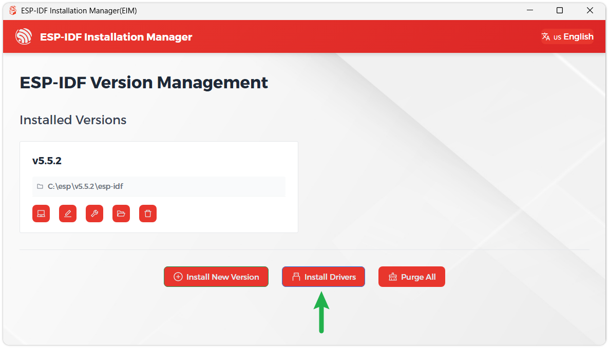
Install Visual Studio Code and the ESP-IDF Extension
Download and install Visual Studio Code.
During installation, it is recommended to check Add "Open with Code" action to Windows Explorer file context menu to facilitate opening project folders quickly.
In VS Code, click the Extensions icon
 in the Activity Bar on the side (or use the shortcut Ctrl + Shift + X) to open the Extensions view.
Enter ESP-IDF in the search box, locate the ESP-IDF extension, and click Install.
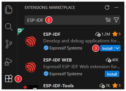
For ESP-IDF extension versions ≥ 2.0, the extension will automatically detect and recognize the ESP-IDF environment installed in the previous steps, requiring no manual configuration.
ESP32-P4-WIFI6-DB Example
The ESP-IDF BSP and example programs for the ESP32-P4-WIFI6-DB are maintained in the ESP32-P4-WIFI6-DB Example. You can obtain the board‑level code and example programs from this repository.
The relevant directories in the repository are:
firmware/esp32_p4_wifi6_db/: ESP-IDF BSP, header files, Kconfig, and component manifest.examples/esp_idf/: Peripheral examples and Brookesia applications.firmware/factory-firmware/: ESP32-P4 firmware for 5, 7, 8, and 10.1inch panels, as well as ESP32-C5 slave firmware.- ESP32-P4-WIFI6-DB Schematic.
The target chip for the example projects is esp32p4.
Quick Run
The following commands use the 00_board_check example. Switch the terminal's current directory to the example directory and run them, replacing COMx with the actual serial port of the ESP32-P4:
cd examples/esp_idf/00_board_check
idf.py set-target esp32p4
idf.py build
idf.py -p COMx flash monitor
Display, camera, and Wi-Fi related examples also require selecting the actually connected LCD panel and entering Wi-Fi credentials via idf.py menuconfig before building. The component manager resolves dependencies during the configuration phase.
LCD Panel Selection
The BSP selects the LCD panel via the following options:
| BSP Option | Panel Controller | Resolution |
|---|---|---|
CONFIG_BSP_LCD_TYPE_720_1280_5_INCH_A | HX8394, 5inch | 720 × 1280 |
CONFIG_BSP_LCD_TYPE_720_1280_7_INCH_A | ILI9881C, 7inch | 720 × 1280 |
CONFIG_BSP_LCD_TYPE_800_1280_8_INCH_A | JD9365, 8inch | 800 × 1280 |
CONFIG_BSP_LCD_TYPE_800_1280_10_1_INCH_A | JD9365, 10.1inch | 800 × 1280 |
The BSP Kconfig defaults to the 10.1inch JD9365, and the default configuration of brookesia_test selects the 8inch JD9365. Before building, select the panel that is actually connected. The default configuration does not override an existing sdkconfig; to confirm the options actually in effect, check the project configuration and the generated build/config/sdkconfig.h.
Recommended Validation Order
It is recommended to run the examples in the following order: first confirm the board‑level peripherals, then verify the display, networking, and other functions:
00_board_check: Board‑level peripheral check.02_i2c_console_test: I2C bus check.03_sdmmc_test: SDMMC check.04_mipi_dsi_test: Display test.06_wifi_test: Wi-Fi Station test.
ESP-IDF Example Index
| Example Directory | Example Content |
|---|---|
00_board_check | Outputs chip, Flash, PSRAM, heap memory information, and periodic heartbeat |
01_gpio_input_test | Displays GPIO input status on the LCD |
02_i2c_console_test | Interactive I2C scan and register read/write console |
03_sdmmc_test | TF file write, read, and rename test |
04_mipi_dsi_test | LCD output test, currently displaying a solid white screen |
05_mipi_csi_test | Uses PPA processing and previews the camera feed on the LCD |
06_wifi_test | Wi-Fi Station networking and gateway ping |
07_i2s_codec | ES8311 built-in audio playback or microphone loopback |
08_usb_host_msc | USB mass storage file operations and sequential read/write speed test |
09_bt_controller_mac_addr | Hosted Bluetooth MAC view/configuration and BLE GATT test |
10_wifi_antenna_tesat | Wi-Fi scan, STA networking, band, and RSSI logging |
brookesia_test | Comprehensive interface including calculator, drawing board, audio, camera, video, settings, Xiaozhi, and GPIO applications |
10_wifi_antenna_tesat is the current directory spelling in the repository. For wiring and operation methods, refer to the README and configuration in each example directory.
Pre‑run Checks
- The board implements wireless functionality via the ESP32-C5 wireless co-processor and ESP-Hosted/SDIO. The ESP32-C5 requires compatible ESP-Hosted slave firmware; flashing an ESP32-P4 example will not update the ESP32-C5.
- The I2C bus uses GPIO7 (SDA) and GPIO8 (SCL), connecting to the ES8311, GT911, LCD backlight controller, and camera SCCB bus.
- The ES8311 I2S signals use GPIO13, GPIO12, GPIO10, GPIO9, and GPIO11, and amplifier enable uses GPIO53.
- The TF uses 4-bit SDMMC, card power enable is GPIO45 (active low), and SDMMC IO power uses LDO channel 4.
- The LCD backlight is controlled via the
0x45device on the shared I2C bus, brightness register0x96; GT911 uses polling mode. - ESP-Hosted/SDIO uses GPIO18, GPIO19, GPIO14, GPIO15, GPIO16, GPIO17, and GPIO54.
- For component versions, configuration requirements, and hardware connection details of specific examples, please refer to the README in the corresponding example directory and the board hardware documentation. Build, flash, and run results must be confirmed separately for the selected example, ESP-IDF version, and actual panel.
ESP32-P4-WIFI6-DB Firmware Flashing and Erasing
The following steps apply to flashing the bin firmware provided for this model when the ESP32-P4-WIFI6-DB is connected to a 10.1inch panel. Before using the firmware, confirm that it matches the ESP32-P4 chip version, Flash size, board model, and panel model.
Flash address:
0x00Firmware download: ESP32-P4-WIFI6-DB-10.1-Inch-A Factory Firmware
For other panel models, select the corresponding BSP panel configuration in the ESP-IDF project and build the firmware yourself. This 10.1inch firmware cannot be used directly.
- Firmware Flashing
- Firmware Erasing
The following steps apply to the firmware provided on this page.
Download and extract Espressif's official Flash Download Tool (Download)
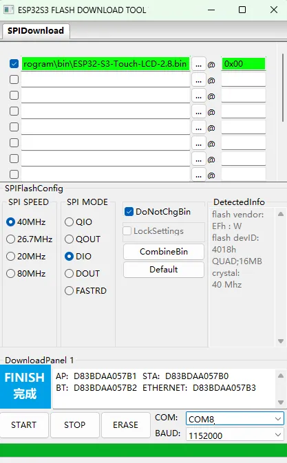
Run Flash Download Tool and select the options that match the development board's MCU and download interface. The screenshot below uses ESP32-S3 and USB as an example; use the options required by the product's hardware design.
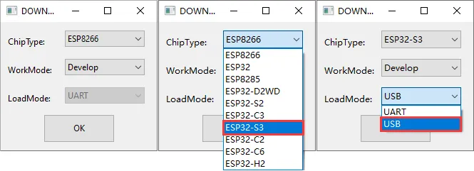
Parameter settings
- Select the COM port for the development board
- Set BAUD to the maximum value, 1152000
- Click the "..." button in the row, select the bin file provided by Waveshare, manually enter the flash address given at the top of this page in the field to its right, and select the leftmost checkbox in the row
- Click START to begin flashing
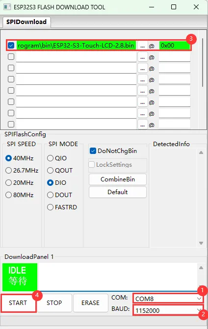
Wait for flashing to complete (this may take some time; please be patient)
Press the reset button and verify the result
Resources
1. Example
The BSP, ESP-IDF examples, and Arduino examples for the ESP32-P4-WIFI6-DB are maintained in the example repository for this model.
2. Hardware Resources
3. Technical Manuals
4. Software Tools
[Tutorial Navigation]
- Features
- Onboard Resources
- Pin Definitions
- Dimensions
- Working with Arduino
- Arduino Getting Started
- Setting Up the Arduino Development Environment
- Arduino Examples
- board_check: Board Information Check
- gpio: GPIO Console
- i2c: I2C Address Scan
- i2s: ES8311 Audio Loopback
- sdmmc: TF File Read/Write
- mipi_dsi: MIPI-DSI LCD
- mipi_csi: Camera Display
- Board Resources and Shared Interfaces
- Working with ESP-IDF
- ESP32-P4-WIFI6-DB Firmware Flashing and Erasing
- Resources