


- sales/support
Google Chat:---
- sales
+86-0755-88291180
- sales01
sales@spotpear.com
- sales02
dragon_manager@163.com
- support
tech-support@spotpear.com
- CEO-Complaints
zhoujie@spotpear.com
- Only Tech-Support
WhatsApp:13246739196
- Purchase/Shipping/Refund
WhatsApp:13424403025
- HOME
- >
- ARTICLES
- >
- Common Moudle
- >
- WIFI
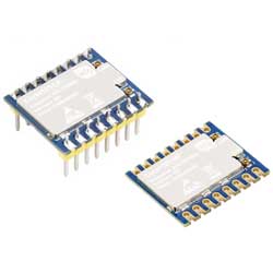
Core1121-HF User Guide
Overview
Introduction
This product is a long-range, ultra-low-power transceiver that supports ISM sub GHz (150-960MHz), global 2.4GHz band, and 1.9-2.1GHz satellite band, suitable for terrestrial and satellite communication applications. It supports LoRa®, (G)FSK, and LR-FHSS modulation methods, and can be used in LoRaWAN® standard networks or private protocols to meet the needs of LPWAN applications. The LR1121 integrates a low-power multi-band RF front-end with extremely high frequency configuration flexibility.
Features
- Adopts the third-generation ultra-low power LoRa® transceiver LR1121 from the Semtech LR11xx series
- Supports Sub-GHz (150–960 MHz), S band (1.9–2.1 GHz), and 2.4GHz ISM bands
- Builds a low-power wide-area network through LoRa or LoRaWAN protocol combined with gateway access to the cloud
- Supports LoRa, (G)FSK, and LR-FHSS modulation modes, and is compatible with the SX126x/SX127x bands, facilitating product upgrades
- SPI interface communication, supporting mainstream MCU platforms, easy to integrate and port
- Integrates AES-128 encryption engine to enhance data security
- Supports TCXO crystal oscillator to ensure frequency stability in high and low temperature conditions
- Suitable for industrial telemetry, smart home, environmental monitoring, remote data acquisition, and other IoT application scenarios
- Provide complete supporting manuals (demos and user manuals for ESP32, Raspberry Pi, STM32, Raspberry Pi Pico, etc.)
Specifications
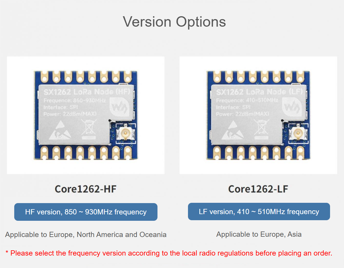
| Version | Core1121-HF | Core1121-LF |
| RF characteristics | ||
| RF chip | LR1121 | |
| Operating frequency band | 850 ~ 930MHz | 410 ~ 510MHz |
| 1900~2100 MHz, 2400~2500MHz | ||
| Signal modulation | LoRa, (G)FSK, LR-FHSS | |
| Communication rate | LoRa: 0.091 ~ 62.5Kbps | |
| (G)FSK: 0.6 ~ 300Kbps | ||
| Transmission power | -9~22dBm@Sub-GHz band, -18~13dBm@ISM band | |
| Reception sensitivity | -127dBm@Sub-GHz band, SF=7, CR4_5, BWL=125KHz | |
| -111dBm@ISM band, SF=7, CR4_5, BWL=800KHz | ||
| Reference communication distance | Sub-GHz band, 5km | |
| ISM band, 2km | ||
| Spreading factor | SF5 ~ SF12 | |
| Electrical characteristics | ||
| Operating voltage | 3.3V (up to 3.8V) | |
| Logic voltage | 3.3V (other logic levels require a level converter) | |
| Module power consumption | Transmission Current: 115mA@22dBm Sub-GHz, 25mA@13dBm ISM | |
| Reception current: 9.2mA@125KHz Sub-GHz, 8.1mA@125KHz ISM | ||
| Hardware characteristics | ||
| Communication port | SPI | |
| Crystal oscillator | TCXO 32MHz | |
| Antenna interface | IPEX-4 or castellated module (Castellated module requires additional operation, please refer to the Wiki information for details) | |
| Antenna Protection | TVS protection | |
| Operating temperature | -40 ~ 85℃ | |
| Port type | Castellated module, 2.54mm pitch | |
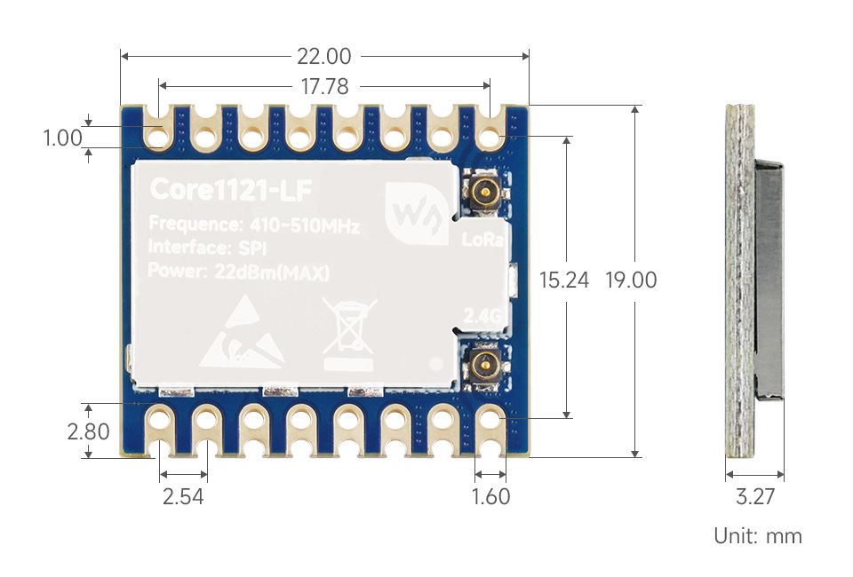
| Dimensions | 19.00mm × 22.00mm | |
- The logic level of the module is 3.3V. If using 5V IO levels, level conversion is required; otherwise, the module may be damaged.
- The communication rate of the module is affected by parameters such as frequency offset and preamble
- Communication distance can be extended further in open environments.
Hardware Selection
Pinout Definition
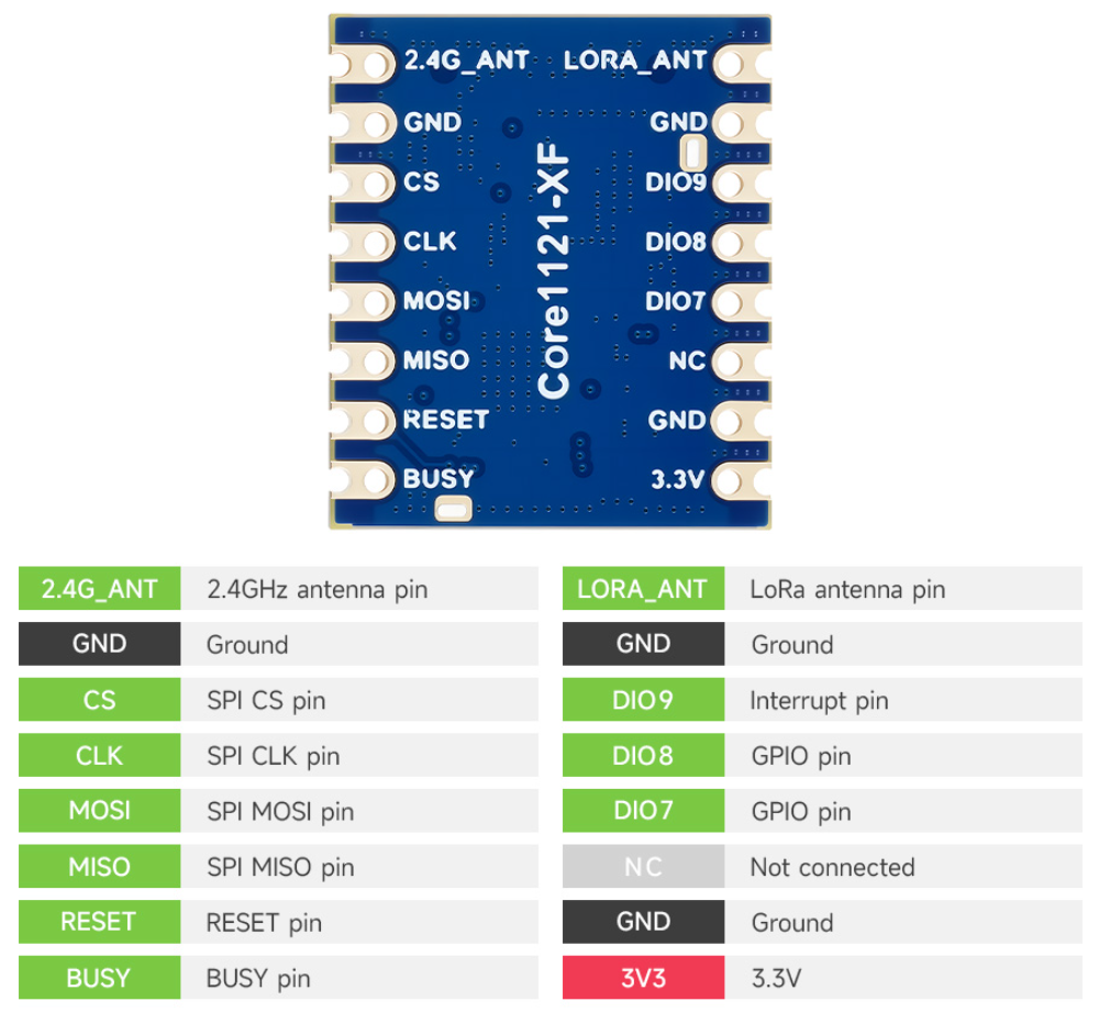
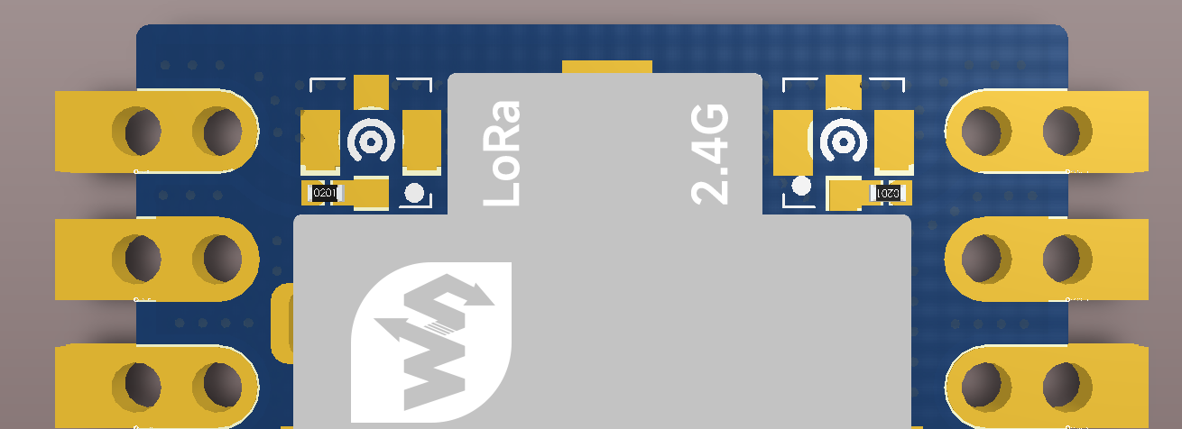
- *_ANT pin is the antenna pin. If you need to use it, you need to remove the IPEX-4 connector and solder a 0Ω 0201 resistor to it. Otherwise, it will be left unconnected, as shown in the figure below:
Communication Introduction
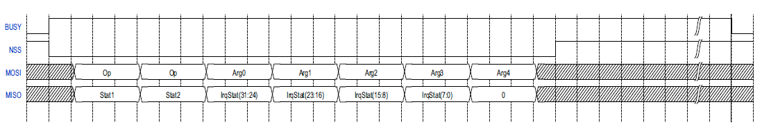
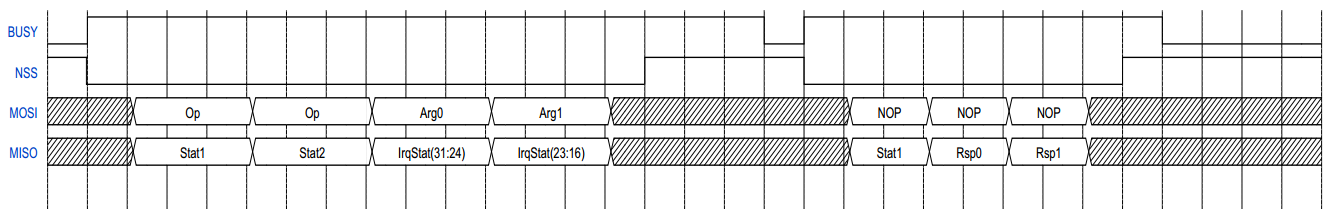
The LR1121 provides a set of APIs that allow the master controller to communicate with the LR1121 through a series of SPI commands/responses. The BUSY signal is used as a handshake mechanism to indicate if the LR1121 is ready to receive commands. Therefore, you must check the status of BUSY before sending a command.
- Write command
- During the write command process, LR1121 will return the status register and interrupt register to the controller via the MOSI pin, depending on the command opcode and parameter length.
- The controller first sends a 16-bit operation code (opcode) and then sends the required parameters.
- When there is a falling edge on the NSS pin, the LR1121 will automatically pull up the BUSY signal to indicate that the command is being processed.
- Once the LR1121 finishes processing the command, the BUSY signal is released (pulled low) to indicate that the device is ready to receive the next command.
- Read command
- Specific read commands are used to get data from the LR1121, such as internal status results, etc.
- The main controller sends a 16-bit operation code (opcode) first, and additional parameters if needed.
- When there is a falling edge on the NSS pin, the BUSY signal automatically pulls up to indicate that the LR1121 is preparing data.
- Once the data is ready, the BUSY signal is released (pulled low) to indicate that the data can be read.
- At this point, the controller removes (reads) the returned data from SPI by continuously sending NOP (0x00 bytes).
- For more instructions, please refer to User Manual
Dimensions
Demo Introduction
- Except for lr1121_firmware_update, lr1121_read, and lr1121_write, the following examples are ported from the Semtech official website lr11xx example.
| Demo | Basic Description |
|---|---|
| lr1121_cad | Execute Channel Activity Detection (CAD) - LoRa only |
| lr1121_firmware_update | LR1121 firmware update tool |
| lr1121_lr_fhss | Transmit LR-FHSS format data packets |
| lr1121_per | Execute data packet error rate (PER) test — Tx and Rx roles |
| lr1121_ping_pong | Initiate data exchange between two devices |
| lr1121_read | Enter receive mode |
| lr1121_sigfox | Send Sigfox-compliant uplinks |
| lr1121_spectral_scan | Get the inst-RSSI values in RX mode to form a heatmap |
| lr1121_spetrum_display | Get the inst-RSSI values in RX mode and form a dynamic spectrum curve |
| lr1121_tx_cw | Tx continuous wave mode |
| lr1121_tx_infinite_preamble | Transmit infinite preamble |
| lr1121_write | Send data periodically |
| lr1121_LoRaWAN | Simple LoRaWAN Class A application |
Demo Description
- Each demo has its own set of parameters, see the .h file in the folder
- lr1121_config is the configuration file, where you can set the parameters, including:
- Packet type (PACKET_TYPE)
- RF frequency (RF_FREQ_IN_HZ)
- Output power (TX_OUTPUT_POWER_DBM)
- Packets and modulation parameters of different modulations
lr1121_cad
- The chip performs CAD operations in LoRa. Define the macro PACKET_TYPE as LR11XX_RADIO_PKT_TYPE_LORA (in the file ../../examples/lr1121_cad/lr1121_config.h) to use this demo code.
- During the CAD test, there are three exit modes that can be defined to suit different use cases. For the LR11XX_RADIO_CAD_EXIT_MODE_STANDBYRC mode, once it is completed, the chip returns to the STBY_RC mode regardless of whether there is activity on the channel. For the LR11XX_RADIO_CAD_EXIT_MODE_RX mode, if activity is detected, the chip will remain in the RX state until a packet is detected or the timer reaches the timeout time defined by CAD_TIMEOUT_MS. For the LR11XX_RADIO_CAD_EXIT_MODE_TX mode, if no activity is detected, the chip will go to TX mode. This mode is actually an alternative to the TX mode, so the payload data for transmission should be preloaded before setting the chip to LR11XX_RADIO_CAD_EXIT_MODE_TX mode.
- There are several parameters that can be updated in the lr1121_cad.h header file:
- CAD_SYMBOL_NUM: Defines the number of symbols used for CAD detection
- CAD_DETECT_PEAK: Defines the sensitivity of the LoRa modem when attempting to associate symbols
- CAD_DETECT_MIN: Minimum peak value, used to filter out situations where there is almost no signal or noise
- CAD_EXIT_MODE: Define the action to be performed after the CAD operation
- CAD_TIMEOUT_MS: Used only when CAD is executed with CAD_EXIT_MODE = LR11XX_RADIO_CAD_EXIT_MODE_RX or LR11XX_RADIO_CAD_EXIT_MODE_TX
- USER_PROVIDED_CAD_PARAMETERS: Set to true, the CAD parameters provided by the user will be used
- DELAY_MS_BEFORE_CAD: Delay between CAD detections
lr1121_firmware_update
- This demo is used to update the firmware of the LR1121 to the latest version, or to flash the LoRaWan firmware to make it compatible with LoRaWan use
- You can uncomment the corresponding firmware header file in the lr1121_firmware_update.h header file. After compiling and flashing, the main controller will perform a firmware update on the LR1121. Only one firmware can be selected at a time
- Different development platforms use different annotation methods, please refer to the following demo instructions
lr1121_lr_fhss
- The application will automatically configure the device to transmit packets in LR-FHSS
- The frequency can be updated in the ../../examples/lr1121_lr_fhss/lr1121_config.h header file
- There are several parameters that can be updated in the lr1121_lr_fhss.h header file:
- TX_TO_TX_DELAY_IN_MS: The time delay between two transmitted data packets
- LR_FHSS_BANDWIDTH: Bandwidth
- LR_FHSS_CODING_RATE: Encoding rate
- LR_FHSS_ENABLE_HOPPING: Enables or disables frequency hopping
- LR_FHSS_GRID: Frequency-hopping grid
- LR_FHSS_HEADER_COUNT: Number of header blocks
- LR_FHSS_MODULATION_TYPE: Modulation type
lr1121_per
- Used to perform PER testing of LoRa and FSK modems. Define the macro PACKET_TYPE as LR11XX_RADIO_PKT_TYPE_LORA or LR11XX_RADIO_PKT_TYPE_GFSK (in the file .. /.. /examples/lr1121_per/lr1121_config.h) to enable each modem in the test.
- In the PER test, the device can be set as either a TX device or an RX device. In addition, there are macros used to control the compilation. To set the device as an RX device, the macro (RECEIVER) must be set to 1; to set the device as a TX device, set it to 0. If set to RX device mode, this application will automatically start PER test reception to receive packets in multiples of NB_FRAME. If set as a TX device, it will start sending data packets infinitely after startup.
- The first byte of the payload is reserved for the rolling counter, which will be used to detect packets that are completely lost in the PER statistic. Keeping the counter in the first byte allows for the minimum payload size. The receiver will inspect the rest of the payload to ensure that the received packets are not unwanted. per_msg is a per_msg that holds the contents of this part of the payload. If PAYLOAD_LENGTH (defined in ../../examples/lr1121_per/lr1121_config.h) is less than 1, the payload check will not be performed because the payload contains only a counter.
- There are several parameters that can be updated in the lr1121_per.h header file:
- RECEIVER: Set to RX or TX device
- RX_TIMEOUT_VALUE: Receive timeout value
- TX_TO_TX_DELAY_IN_MS: The time delay between two transmitted data packets
- NB_FRAME: Conduct a Per Second Error Rate (PER) test on the number of data packets
lr1121_ping_pong
- Set the device to ping-pong mode.
- The demo code will be used to perform LoRa and FSK modem testing. Define the macro PACKET_TYPE as LR11XX_RADIO_PKT_TYPE_LORA or LR11XX_RADIO_PKT_TYPE_GFSK (in the file .. /.. /examples/lr1121_ping_pong/lr1121_config.h) to enable each modem in the test.
- This application allows devices to operate in either master or slave mode during a ping-pong test When the device starts, it assumes the master mode and alternates between sending "PING" packets and receiving "PONG" packets. When it receives a "PING" packet, the device switches to slave mode, then sends a "PONG" packet and waits to receive a "PING" packet. In slave mode, if the device receives a "non-PING" packet, it resets to master mode and restarts the previous process.
- There are several parameters that can be updated in the lr1121_ping_pong.h header file:
- RX_TIMEOUT_VALUE: Receive timeout value
lr1121_read
- Set the device to receive mode.
- The demo code will be used to perform LoRa and FSK modem testing. Define the macro PACKET_TYPE as LR11XX_RADIO_PKT_TYPE_LORA or LR11XX_RADIO_PKT_TYPE_GFSK (in the file .. /.. /examples/lr1121_read/lr1121_config.h) to enable each modem in the test.
- Continuously read information, which can be paired with another device for testing with lr1121_write
lr1121_sigfox
- This demo code illustrates the transmission of an uplink that complies with the Sigfox standard.
- There is currently a predefined physical payload (corresponding to the "0x01" application payload).
- To send another payload, you can update the sample0 array and SIGFOX_PAYLOAD_LENGTH macro in lr1121_sigfox.*.
- There are several parameters that can be updated in the lr1121_sigfox.h header file:
- TX_TO_TX_DELAY_IN_MS: The time delay between two transmitted data packets
lr1121_spectral_scan
- The application achieves spectrum scanning operations by setting the device to Rx continuous mode and periodically reading the instantaneous RSSI value for each frequency channel one by one. For each channel, the RSSI value is sampled NB_SCAN times using the GetRssiInst function. The chip then switches to the next channel to repeat the same process. Each frequency channel has a statistics displayed as a histogram. On the terminal screen, the histogram is shown as a numerical array following the corresponding frequency values. All these statistics together form the electromagnetic environment heatmap. In each histogram statistic, each number represents the height of the histogram column, and the order of the array indicates the range of RSSI values from 0 dBm to -128 dBm. The length of the array depends on the scale of the RSSI level RSSI_SCALE. The X-axis represents the background electromagnetic noise level, while the Y-axis represents the probability of the result falling into a level slot.
- For example: Assume we see a line "INFO: 2400.000 MHz: 0 0 0 0 0 0 0 0 0 0 0 0 0 0 0 0 0 0 0 0 0 0 0 0 0 0 16 76 8 0 0 0 0 0" in the terminal. We can calculate that the length of this array is 33, so it is RSSI_SCALE = (RSSI_TOP_LEVEL-RSSI_BOTTOM_LEVEL)/(33-1) = (0-(-128))/32 = 4dBm. This is equivalent to the histogram below.
   0   0   0   0 ... 0   16  76  8   0   0   0   0   0
 ^
 |                            _
 |                           | |
 |                           | |
 |                           | |
 |                           | |
 |                        _  | |
 |                       | | | |  _
 | _____________._._.____| |_| |_| |__________________
 +-------------- ... -------------------------------------->
  /0dBm   /-8dBm ... /-96dBm /-104dBm/-112dBm/-120dBm/-128dBm
- The demo code will be used for testing under LoRa and FSK modems, but there should be no difference if the bandwidth is the same. Define the macro PACKET_TYPE as LR11XX_RADIO_PKT_TYPE_LORA or LR11XX_RADIO_PKT_TYPE_GFSK (in the file .. /.. /examples/lr1121_spectral_scan/lr1121_config.h) to enable each modem in the test.
- Several parameters can be updated in the header file ../../examples/lr1121_spectral_scan/lr1121_config.h:
- PACKET_TYPE: Set the modem that will be used
- LORA_BANDWIDTH: The bandwidth of LoRa packets
- FSK_BANDWIDTH: The bandwidth of GFSK packets
- There are several parameters that can be updated in the lr1121_spectral_scan.h header file:
- FREQ_START_HZ: The frequency of the first channel for scanning
- NB_CHAN: The number of channels that need to be scanned
- NB_SCAN: The number of scan points per frequency scan
- PACE-S: The number of seconds between two scans in a thread
- WIDTH_CHAN_HZ: The width between each channel
- RSSI_TOP_LEVEL_DBM: The highest RSSI value, default: 0dBm
- RSSI_BOTTOM_LEVEL_DBM: The lowest RSSI value, default: -128dBm
- RSSI_SCALE: The RSSI scale displayed in the spectrum scan
lr1121_spetrum_display
- The application achieves spectrum display operations by setting the device to Rx continuous mode and periodically reading the instantaneous RSSI of each channel one by one. The spectrum covering all the channels being scanned will be plotted on the terminal screen. Starting from the start channel frequency defined by FREQ_START_HZ, the GetRssiInst function will be used to obtain one sampling point at the RSSI level for each channel. Once all channel RSSI values have been collected, a spectral curve is plotted on the terminal screen. This curve will be refreshed every PACE_S seconds, repeating the previous steps.
- The following is an example of the curve displayed on the terminal screen. The bottom of the curve indicates the background noise around the antenna within the scan band. Peaks indicate which channels have RF activity. The frequency box displayed below the X-axis indicates the band being scanned. The Y-axis represents the RSSI level.
   ^
   0|
  -4|
  -8|
 -12|
 -16|
    .
    .
    .
 -76|
 -80|                          _
 -84|                    _    | |
 -88|                  _| |   | |
 -92|_                |   |   | |              _
 -96| |               |   |   | |             | |              _
-100| |               |   |   | |             | |             |
-104| |            _  |   |_._| |_     _     _| |             |
-108| |_._._._._._| |_|           |_._| |_._|   |_._._._._._._|
-112|
-116|
-120|
-124|
-128|
/dBmx------------------------------------------------------------>
    2400 --> 2406 MHz
- The drawing function requires support from VT100 control code. Therefore, in order for this demonstration to run normally, a terminal that supports VT100 control codes (such as MobaXterm) is needed.
- The demo code will be used for testing under LoRa and FSK modems, but there should be no difference if the bandwidth is the same. Define the macro PACKET_TYPE as LR11XX_RADIO_PKT_TYPE_LORA or LR11XX_RADIO_PKT_TYPE_GFSK (in the file .. /.. /examples/lr1121_spetrum_display/lr1121_config.h) to enable each modem in the test.
- Several parameters can be updated in the header file ../../examples/lr1121_spetrum_display/lr1121_config.h:
- PACKET_TYPE: Set the modem that will be used
- LORA_BANDWIDTH: The bandwidth of LoRa packets
- FSK_BANDWIDTH: The bandwidth of GFSK packets
- There are several parameters that can be updated in the lr1121_spectral_scan.h header file:
- FREQ_START_HZ: The frequency of the first channel for scanning
- NB_CHAN: The number of channels that need to be scanned
- PACE-S: The number of seconds between two scans in a thread
- WIDTH_CHAN_HZ: The width between each channel
- RSSI_TOP_LEVEL_DBM: The highest RSSI value, default: 0dBm
- RSSI_BOTTOM_LEVEL_DBM: The lowest RSSI value, default: -128dBm
- RSSI_SCALE: The RSSI scale displayed in the spectrum
lr1121_tx_cw
- Set the device to Tx continuous wave mode.
- General parameters can be updated in the ../../examples/lr1121_tx_cw/lr1121_config.h header file.
lr1121_tx_infinite_preamble
- Set the device to transmit infinite preamble.
- General parameters can be updated in the ../../examples/lr1121_tx_infinite_preamble/lr1121_config.h header file.
lr1121_write
- Set the device to send mode.
- The demo code will be used to perform LoRa and FSK modem testing. Define the macro PACKET_TYPE as LR11XX_RADIO_PKT_TYPE_LORA or LR11XX_RADIO_PKT_TYPE_GFSK (in the file .. /.. /examples/lr1121_write/lr1121_config.h) to enable each modem in the test.
- Periodically send information, which can be paired with another device for testing with lr1121_read
lr1121_LoRaWAN
- This demo demonstrates how to send uplinks periodically in a LoRaWAN Class A application and manually trigger an uplink by pressing a button.
- The application automatically submits a join request to the LoRa network server.
- Once a join acceptance message is received, the uplink is sent periodically.
- Pressing the button or connecting the designated pin to GND will immediately send an uplink on port 102.
- There are some constants set in lr1121_LoRaWAN.h, and their values can be set to define the LoRaWAN configuration of the application.
- PERIODICAL_UPLINK_DELAY_S: Periodic uplink link alarm delay (seconds)
- EXTI_BUTTON: The pin number of the button
- LORAWAN_APP_DATA_MAX_SIZE: The size of the user application data buffer.
- LORAWAN_REGION_USED: LoRaWAN regulatory area.
- LR1121 is pre-configured with ChipEUI/DevEUI and JoinEUI. If the USE_LR11XX_CREDENTIALS in the lorawan_comissioning.h file is set to true, the application will use these identifiers.
- Alternatively, you can provide your own EUI in Inc/apps/lorawan_commissioning/lorawan_commissioning.h by setting USE_LR11XX_CREDENTIALS to false and changing the values of LORAWAN_DEVICE_EUI, LORAWAN_JOIN_EUI, LORAWAN_NWK_KEY, and LORAWAN_APP_KEY.
- User button settings
- ESP32: GPIO0
- Pico: GP0
- Raspberry Pi: BCM26
- STM32: PC13
General Parameters Introduction
- The general parameters are stored in the lr1121_config.h of each demo, and the role of each parameter is described below
| Constant | Description |
|---|---|
| PACKET_TYPE | Packet type, which will be LoRa or GFSK |
| RF_FREQ_IN_HZ | Frequency of sending or receiving data packets |
| TX_OUTPUT_POWER_DBM | Power level for sending data packets |
| FALLBACK_MODE | Backup mode setting |
| ENABLE_RX_BOOST_MODE | RX enhanced mode setting |
| PAYLOAD_LENGTH | Packet payload length for LoRa and GFSK modems |
| LORA_BANDWIDTH | Send Sigfox-compliant uplinks |
| LORA_SPREADING_FACTOR | Spreading factor of LoRa data packet |
| LORA_CODING_RATE | Coding rate of LoRa data packets |
| LORA_PREAMBLE_LENGTH | Length of the preamble in LoRa data packet |
| LORA_PKT_LEN_MODE | Header type, explicit (default) or implicit header |
| LORA_IQ | Are I and Q reversed |
| LORA_CRC | CRC on or off |
| LORA_SYNCWORD | Synchronization word used in LoRa packet |
| FSK_FDEV | Frequency deviation of GFSK modulation |
| FSK_BITRATE | Bit rate of GFSK packet |
| FSK_BANDWIDTH | Bandwidth of GFSK packet |
| FSK_PULSE_SHAPE | Define the filtering applied to GFSK packets |
| FSK_PREAMBLE_LENGTH | Length of the preamble in GFSK packet |
| FSK_PREAMBLE_DETECTOR | Length of GFSK packet preamble detector |
| FSK_SYNCWORD_LENGTH | Length of synchronization word in GFSK packet |
| FSK_ADDRESS_FILTERING | Address filtering option |
| FSK_HEADER_TYPE | GFSK packet type, fixed payload length or variable |
| FSK_CRC_TYPE | GFSK packet CRC option |
| FSK_DC_FREE | Option to enable GFSK packet whitening |
| gfsk_sync_word | Synchronization word of GFSK packet |
| FSK_WHITENING_SEED | Whitening seed for GFSK packets, requires enabling FSK_DC_FREE to be effective |
| FSK_CRC_SEED | CRC seed for GFSK packets, requires setting FSK_CRC_TYPE to be effective |
| FSK_CRC_POLYNOMIAL | CRC polynomial for GFSK packets, requires setting FSK_CRC_TYPE to the appropriate mode |
| FSK_NODE_ADDRESS | Node address for GFSK packet filtering, requires FSK_ADDRESS_FILTERING to be set to the corresponding mode |
| FSK_BROADCAST_ADDRESS | Broadcast address for GFSK packet filtering, requires FSK_ADDRESS_FILTERING to be set to the corresponding mode |
| SIGFOX_RC | Sigfox RC mode - can be 1 or 2 |
Demo Usage
- The following example requires two Core1121-XF modules for communication testing
ESP32
- The installation of the development environment will not be explained in detail. If there are any uncertainties, you can refer to our relevant development board materials for installation. For example: ESP32-S3-Touch-LCD-7B
Hardware Connection
| ESP32-S3-DEV-KIT-N16R8-M | Core1121-XF |
| 3V3 | 3.3V |
| GND | GND |
| GPIO5 | MISO |
| GPIO6 | MOSI |
| GPIO7 | CLK |
| GPIO15 | CS |
| GPIO16 | RESET |
| GPIO39 | BUSY |
| GPIO40 | DIO9 |
Arduino
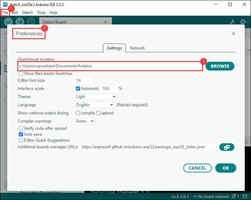
- Download the Demo, go to ../Core1121_XF_Demo/esp32s3/Arduino, copy waveshare_lroa_1121 to to the libraries folder in the project folder. The project folder path can be found under
File->Preferences->Sketchbook location
- After copying, open the Arduino IDE and you can see all the examples under
File->Examples->waveshare lora spiand then you can flash and test
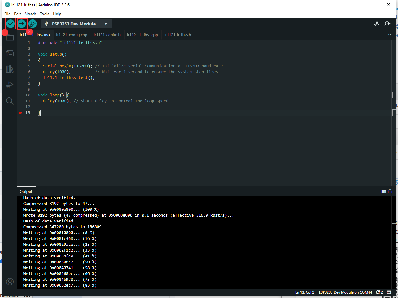
- After setting up the environment, choose the correct port for the development board. If you are unsure about how to flash it, refer to the following diagram:
①: Compile the demo
②: Complie and upload
ESP-IDF
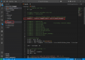
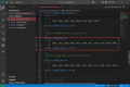
- Download the Demo, go to ../Core1121_XF_Demo/esp32s3/ESP-IDF, use vs code to open the demo
- The demo usage for ESP-IDF requires configuring the script file in ../Core1121_XF_Demo/esp32s3/ESP-IDF/main/CMakeLists.txt. By default, it is set to the lr1121_ping_pong demo. If you need other demos, simply uncomment as shown in the figure below:
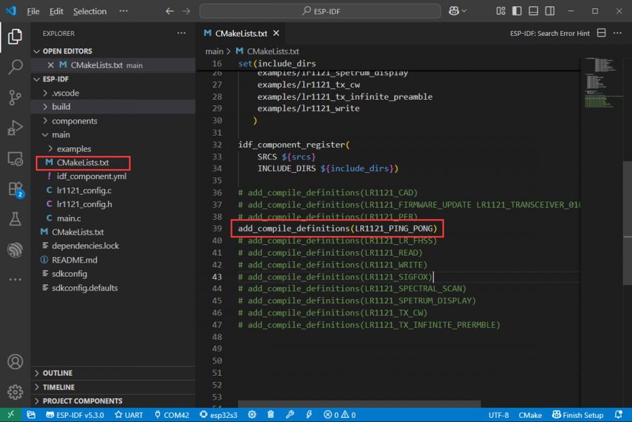
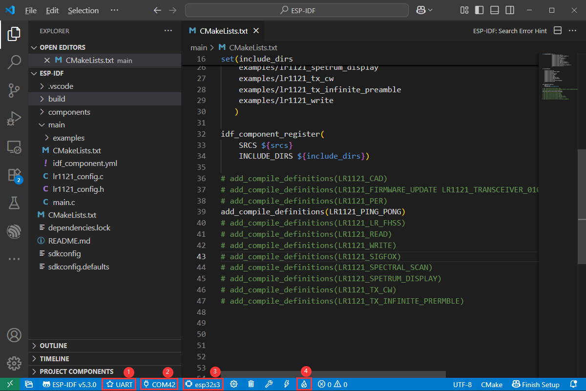
- After setting up the environment, choose the correct port for the development board. If you are unsure about how to flash it, refer to the following diagram:
①: Select UART
②: Select port
③: Select chip
④: Compile and flash
PlatformIO
- Download the Demo, go to ../Core1121_XF_Demo/esp32s3/PlatformIO, use vs code to open the demo
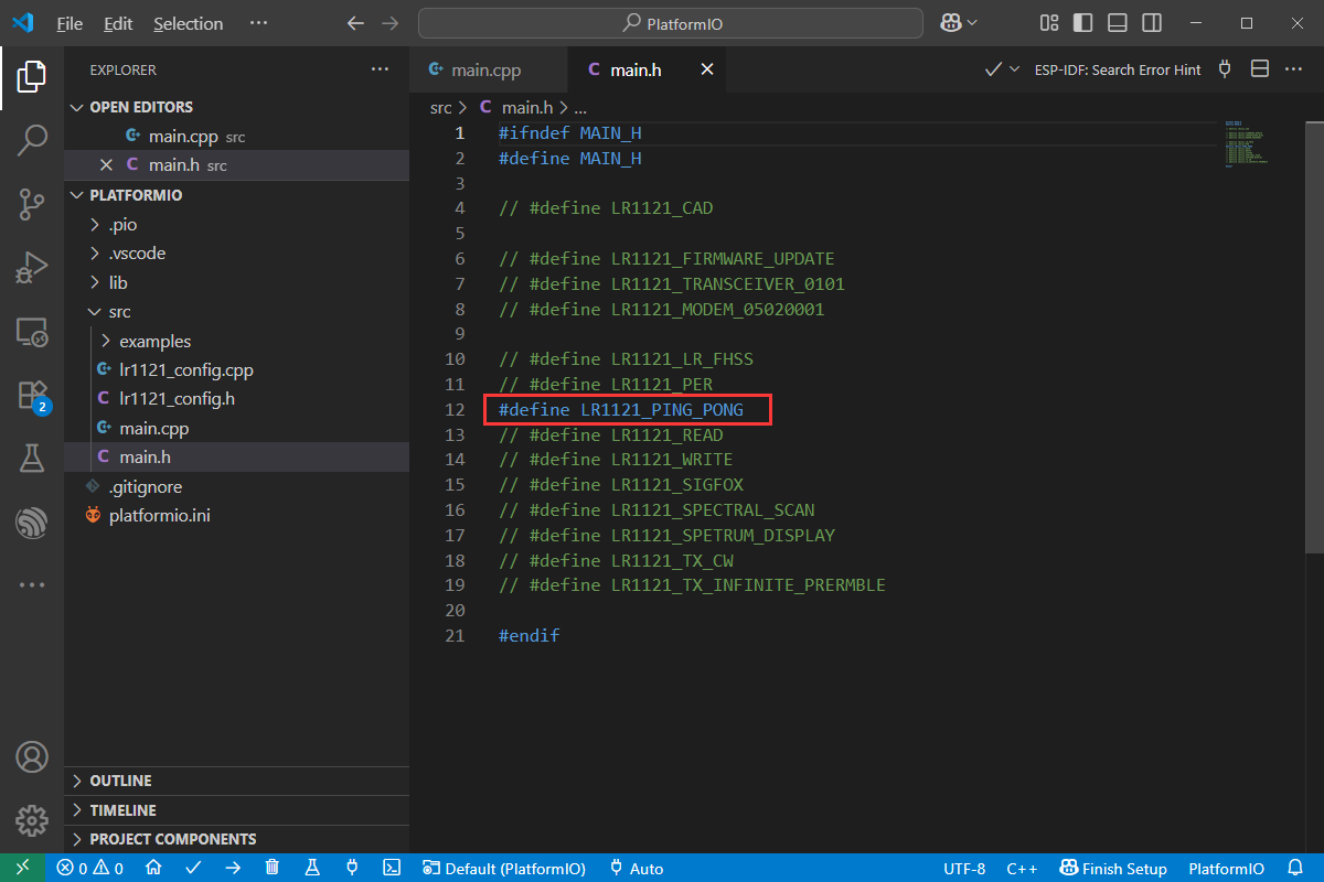
- The demo usage for PlatformIO requires configuring the main.h file in ../Core1121_XF_Demo/esp32s3/PlatformIO/src. By default, it is set to the lr1121_ping_pong demo. If you need other demos, simply uncomment as shown in the figure below:
- After setting up the environment, choose the correct port for the development board. If you are unsure about how to flash it, refer to the following diagram:
①: Select port
②: Compile and flash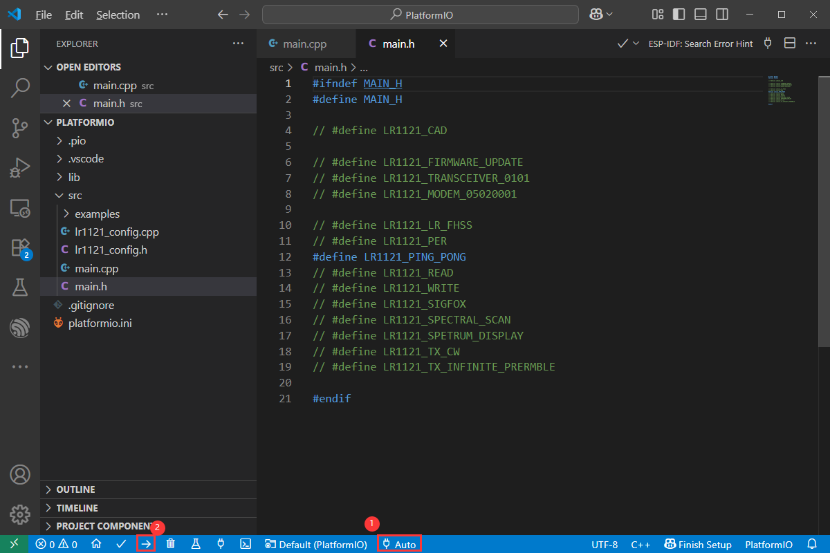
Pico
- The installation of the development environment will not be explained in detail. If there are any uncertainties, you can refer to our relevant development board materials for installation. For example: Raspberry Pi Pico
Hardware Connection
| Raspberry Pi Pico | Core1121-XF |
| 3V3 | 3.3V |
| GND | GND |
| GP12 | MISO |
| GP11 | MOSI |
| GP10 | CLK |
| GP13 | CS |
| GP5 | RESET |
| GP14 | BUSY |
| GP15 | DIO9 |
C
- Download the Demo, go to ../Core1121_XF_Demo/pico, use vs code to open the demo
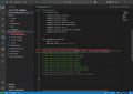
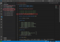
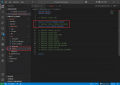
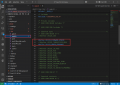
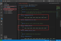
- The demo usage requires configuring the script file in ../Core1121_XF_Demo/pico/CMakeLists.txt. By default, it is set to the lr1121_ping_pong demo. If you need other demos, simply uncomment as shown in the figure below:
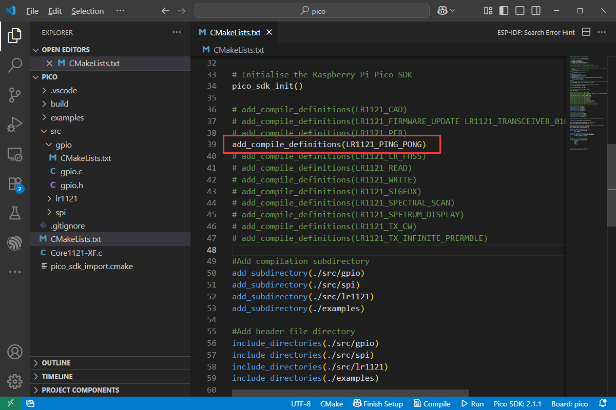
- After setting up the environment, opening the demo will automatically load the tool. If you are unsure about how to flash it, refer to the following diagram:
①: Compile
②: Flash: Pico needs to be put into boot mode to flash. If it cannot be flashed even after entering boot mode, you can manually drag the UF2 file into the build folder to flash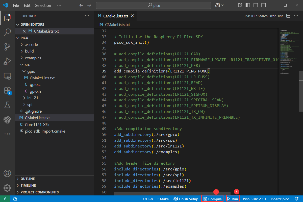
- If you are using Pico w, Pico2 and Pico2 w, you can switch by following the steps shown in the figure below:
①: Modify the development board
②: Select the required development board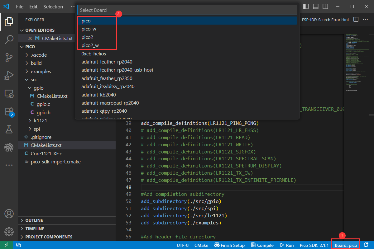
RPI
- The installation of the development environment will not be explained in detail. If there are any uncertainties, you can refer to our relevant development board materials for installation. For example:
Raspberry Pi Documentation
- This demo has been verified on PI4 and PI5
Hardware Connection
| Raspberry Pi (BCM) | Core1121-XF |
| 3V3 | 3.3V |
| GND | GND |
| 9 | MISO |
| 10 | MOSI |
| 11 | CLK |
| 8 | CS |
| 22 | RESET |
| 23 | BUSY |
| 24 | DIO9 |
WiringPi
- Open SPI with the following command:
sudo raspi-config nonint do_spi 0
- Download the WiringPi library:
sudo git clone https://github.com/WiringPi/WiringPi
cd WiringPi
sudo ./build
gpio -v
# Run gpio -v and version 2.70 or higher will appear. If it does not appear, there is an installation error
- Download the demo:
sudo apt-get install unzip -y
sudo wget https://files.waveshare.com/wiki/Core1121/Core1121_XF_Demo.zip
sudo unzip ./Core1121_XF_Demo.zip
cd Core1121_XF_Demo/raspberrypi/
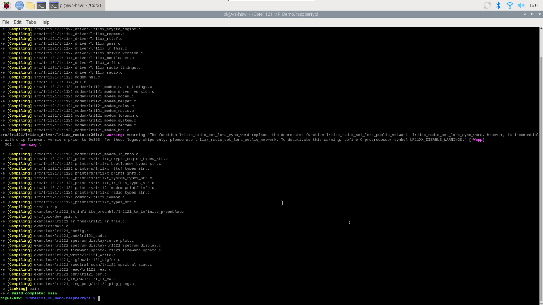
- The demo usage requires configuring the script file in ../Core1121_XF_Demo/raspberrypi/Makefile. By default, it is set to the lr1121_ping_pong demo. If you need other demos, simply uncomment as shown in the figure below:
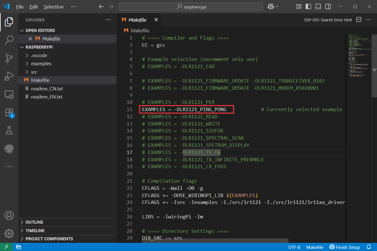
- After entering the project path, you can compile and run the demo. The steps are as follows:
make -B -j
./main
The appearance of the following content indicates that the compilation is complete, then you can run the demo by executing ./main.
STM32
- The development board used is NUCLEO-F446RE
- The installation of the development environment will not be explained in detail. If there are any uncertainties, you can refer to our relevant development environment materials for installation. For example: STM32CubeIDE
Hardware Connection
| NUCLEO-F446RE | Core1121-XF |
| 3V3 | 3.3V |
| GND | GND |
| PA6 | MISO |
| PA7 | MOSI |
| PA5 | CLK |
| PA8 | CS |
| PA0 | RESET |
| PB3 | BUSY |
| PB4 | DIO9 |
STM32CubeIDE
- Download the Demo, go to ../Core1121_XF_Demo/stm32, click .project file to open the demo
- The demo usage requires configuring the ../Core1121_XF_Demo/stm32/Core/inc/main.h file. By default, it is set to the lr1121_ping_pong demo. If you need other demos, simply uncomment as shown in the figure below:
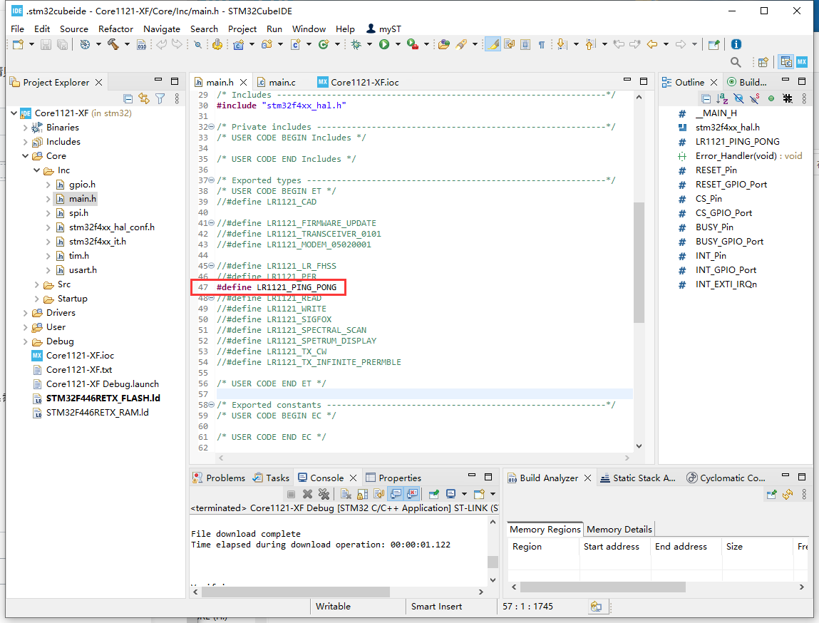
- After opening the project, connect the development board. If you don't know how to flash it, refer to the following image:
①: Compile and flash
Demo Effect Demonstration
lr1121_cad
- For CAD testing, one device flashes the CAD_EXIT_MODE to TX and the other CAD_EXIT_MODE to RX, and the test can be started
- The effect is as follows:
lr1121_firmware_update
- Flash the transmitter/receiver version 0101 firmware by default. If you need to test other firmware versions, comment out the #include "lr1121_transceiver_0101.h" in lr1121_firmware_update.h and uncomment other header files to compile and flash. Only one firmware can be selected for flashing at a time.
- The effect is as follows:
lr1121_lr_fhss
- The application will configure the device to transmit packets in LR-FHSS
- The effect is as follows:
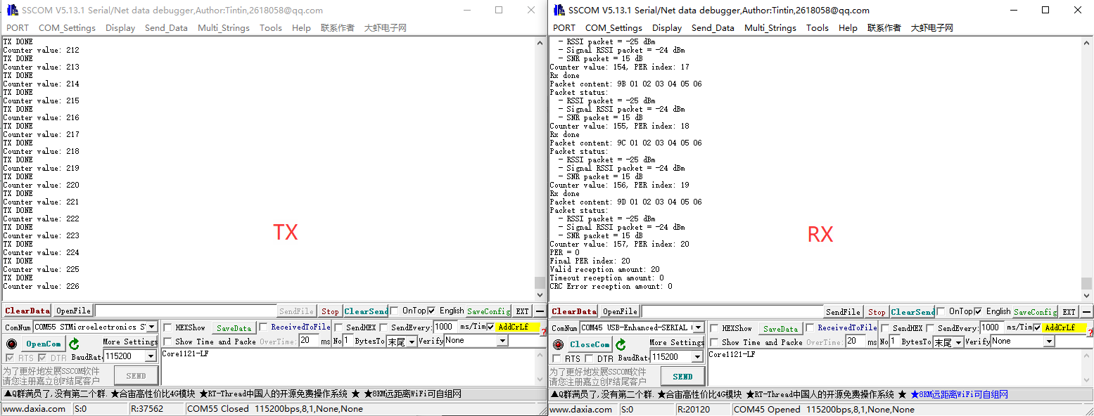
lr1121_per
- PER (Packet Error Rate) testing, in lr1121_per.h set one device to send by defining #define RECEIVER 1, and the other device to receive by defining #define RECEIVER 0
- The effect is as follows:
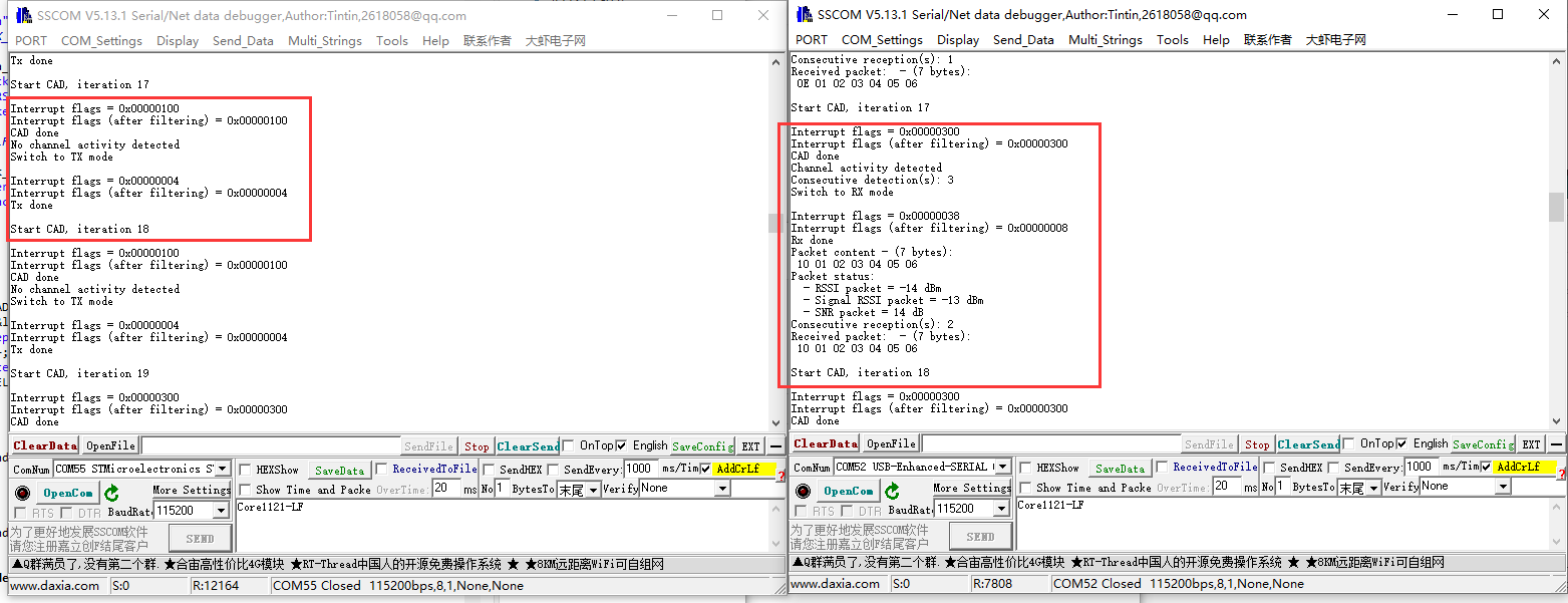
lr1121_ping_pong
- The application sets the device to ping-pong mode (point-to-point bidirectional communication test).
- The effect is as follows:

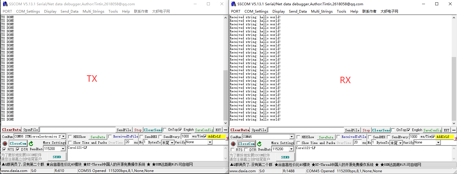
lr1121_read
- The application sets the device to read mode, automatically recognizing strings and hexadecimal numbers, and can be used in conjunction with lr1121_write to achieve point-to-point communication.
- The effect is as follows:

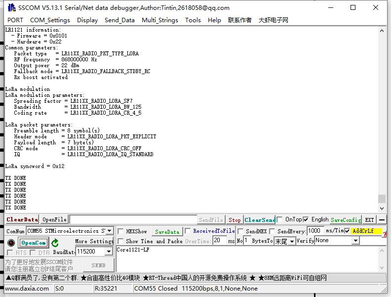
lr1121_write The application sets the device to write mode, automatically sends data, and paired with lr1121_read, it can achieve point-to-point communication.
- The effect is as follows:
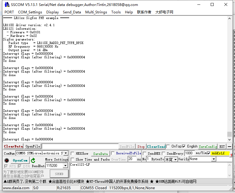
lr1121_sigfox
- This demo code illustrates the transmission of an uplink that complies with the Sigfox standard.
- The effect is as follows:
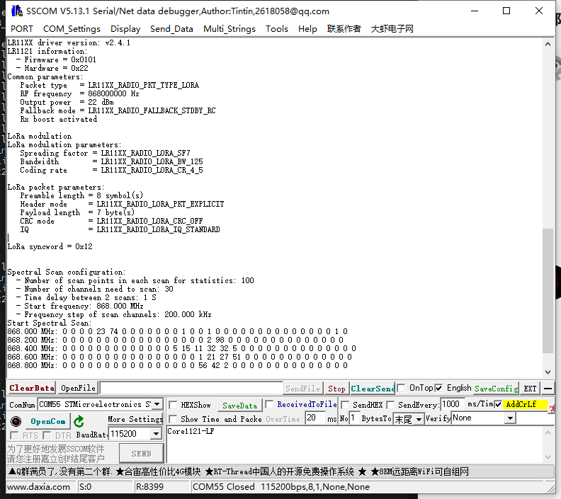
lr1121_spectral_scan
- The application achieves spectrum scanning operations by setting the device to Rx continuous mode and periodically reading the instantaneous RSSI value for each frequency channel one by one.
- It can be tested with lr1121_tx_cw.
- Use lr1121_tx_cw to send a signal at 868MHz with 22dBm power for testing. The results are as follows:
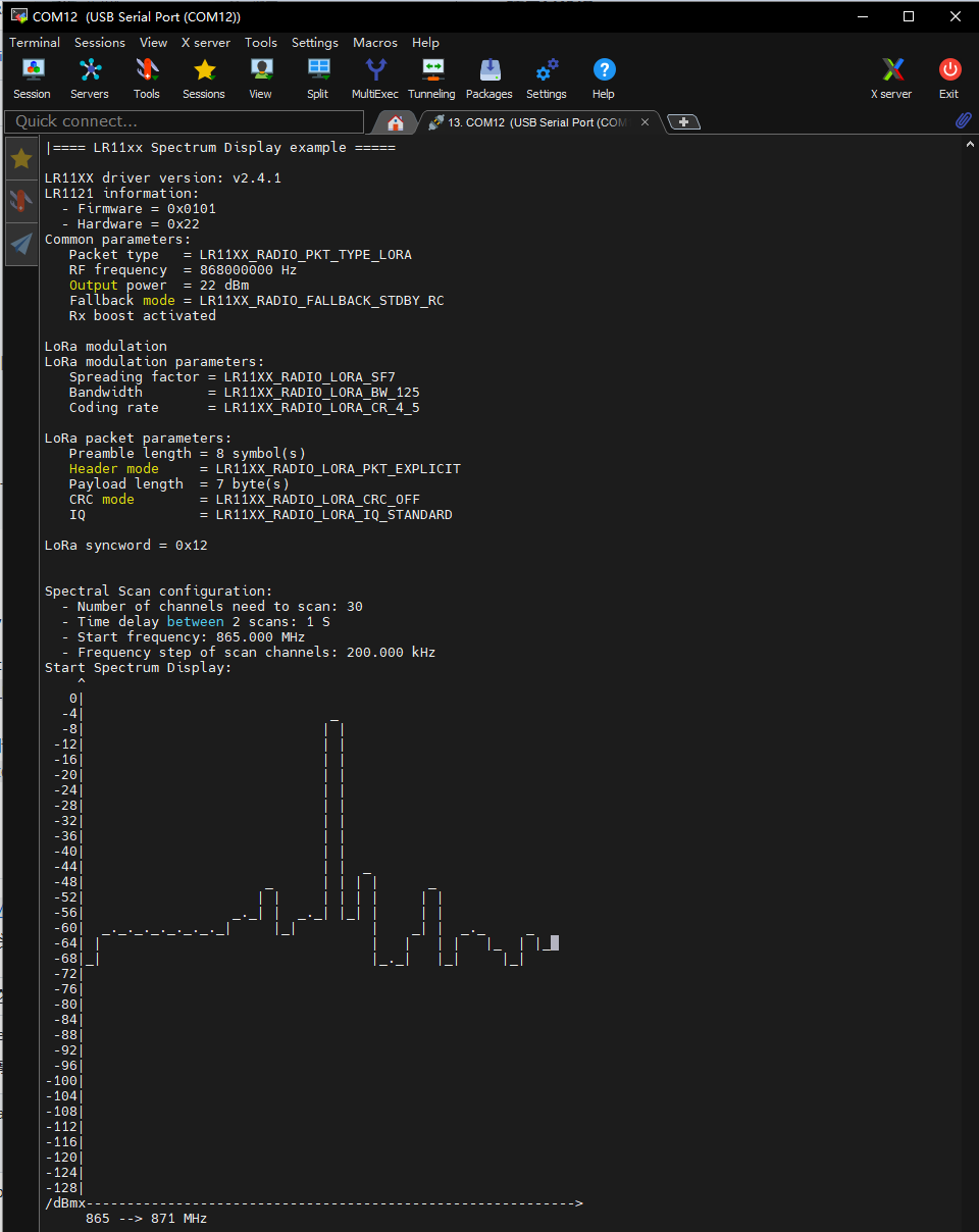
lr1121_spetrum_display
- The application achieves spectrum display operations by setting the device to Rx continuous mode and periodically reading the instantaneous RSSI of each channel one by one.
- It can be tested with lr1121_tx_cw.
- The drawing function requires support from VT100 control code, such as MobaXterm
- Use lr1121_tx_cw to send a signal at 868MHz with 22dBm power for testing. The results are as follows:
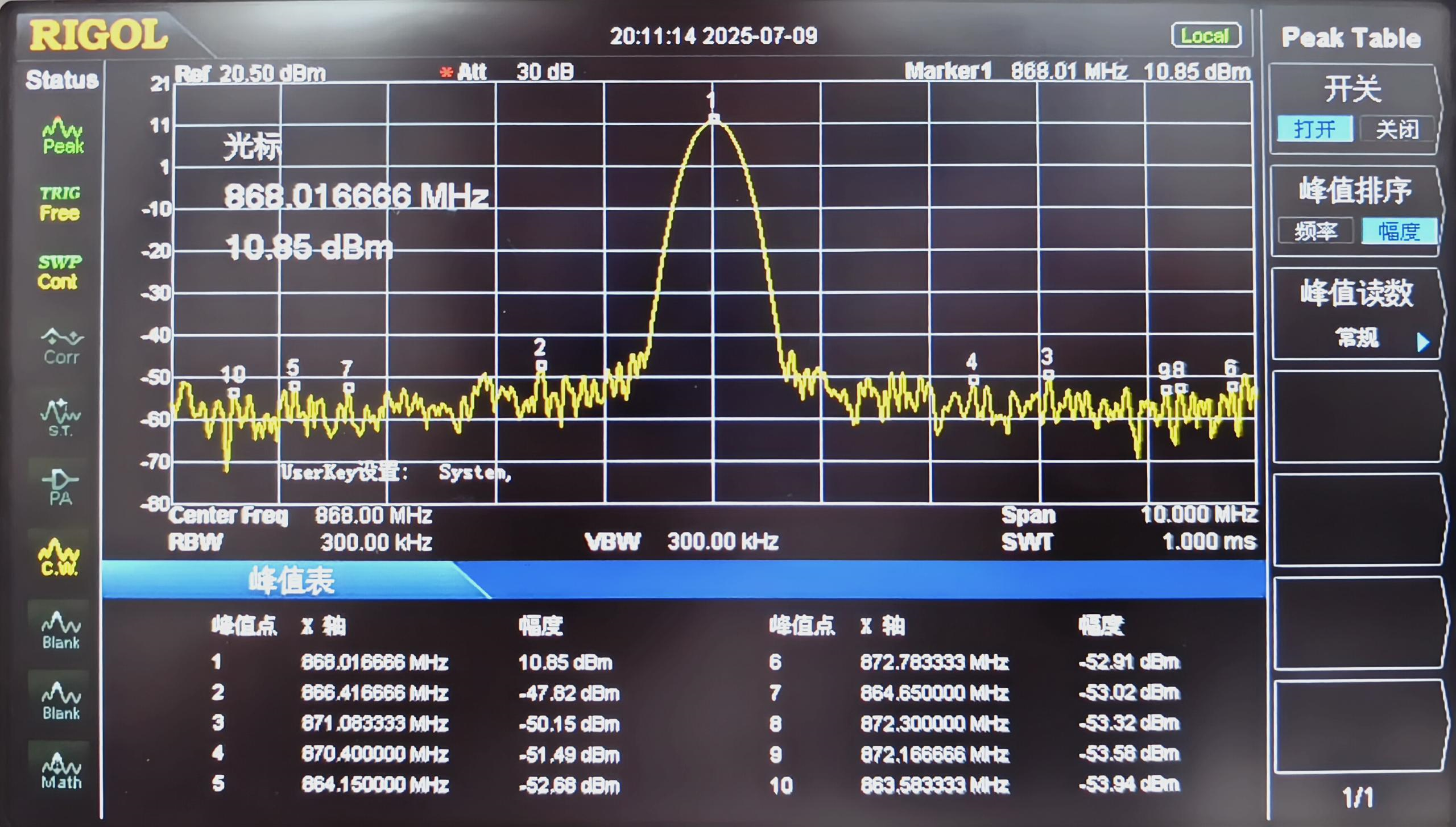
lr1121_tx_cw
- This demo will automatically set the device to Tx continuous wave mode.
- It will continuously emit a waveform, which is an unmodulated sine wave (pure carrier), mainly for testing power, frequency accuracy, and EMC
- No communication capability (no data transmission), non-LoRa protocol format
- The waveform power has attenuated by 10 dBm
lr1121_tx_infinite_preamble
- This demo will configure the device to continuously transmit a wireless preamble signal (Preamble).
- It will continuously transmit a waveform that is modulated (in LoRa format), primarily for testing LoRa transmission performance, spectrum, and certification (LoRa mode).
- It does not transmit a full packet, but uses a valid LoRa preamble code modulation.
LoRa and LoRaWAN
What is LoRa?
LoRa from Semtech is a long-range, low-power IoT wireless platform, generally referring to RF chips that use LoRa technology. The main features are as follows:
- LoRa (short for long range) uses spread spectrum modulation technology derived from Chirp Spread Spectrum (CSS) technology, which is a type of long-distance wireless transmission technology and LPWAN communication technology. Spread spectrum technology trades bandwidth for sensitivity. Wi-Fi, ZigBee, and others all use spread spectrum technology, but the characteristic of LoRa modulation is that it approaches the limit of Shannon's theorem and maximizes sensitivity. Compared to traditional FSK technology, under the same communication rate, LoRa is 8 to 12 dBm more sensitive than FSK. Currently, LoRa primarily operates in the Sub-GHz ISM frequency band.
- LoRa technology integrates technologies such as digital spread spectrum, digital signal processing, and forward error correction coding, significantly improving long-distance communication performance. The link budget of LoRa is superior to any other standardized communication technology, and the link budget refers to the main factors that determine the distance in a given environment.
- LoRa RF chips mainly include the SX127X series, SX126X series, and SX130X series, where the SX127X and SX126X series are used for LoRa nodes, and the SX130X is used for LoRa gateways. For more details, please refer to the product list of Semtech.
What is LoRaWAN?
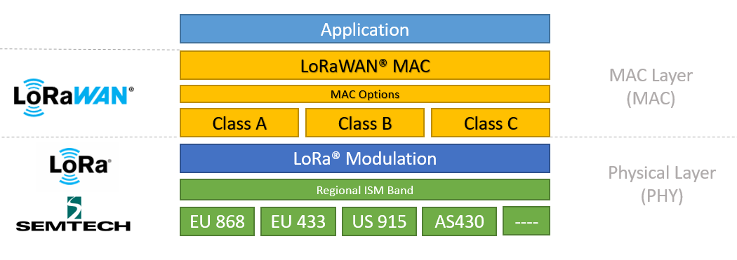
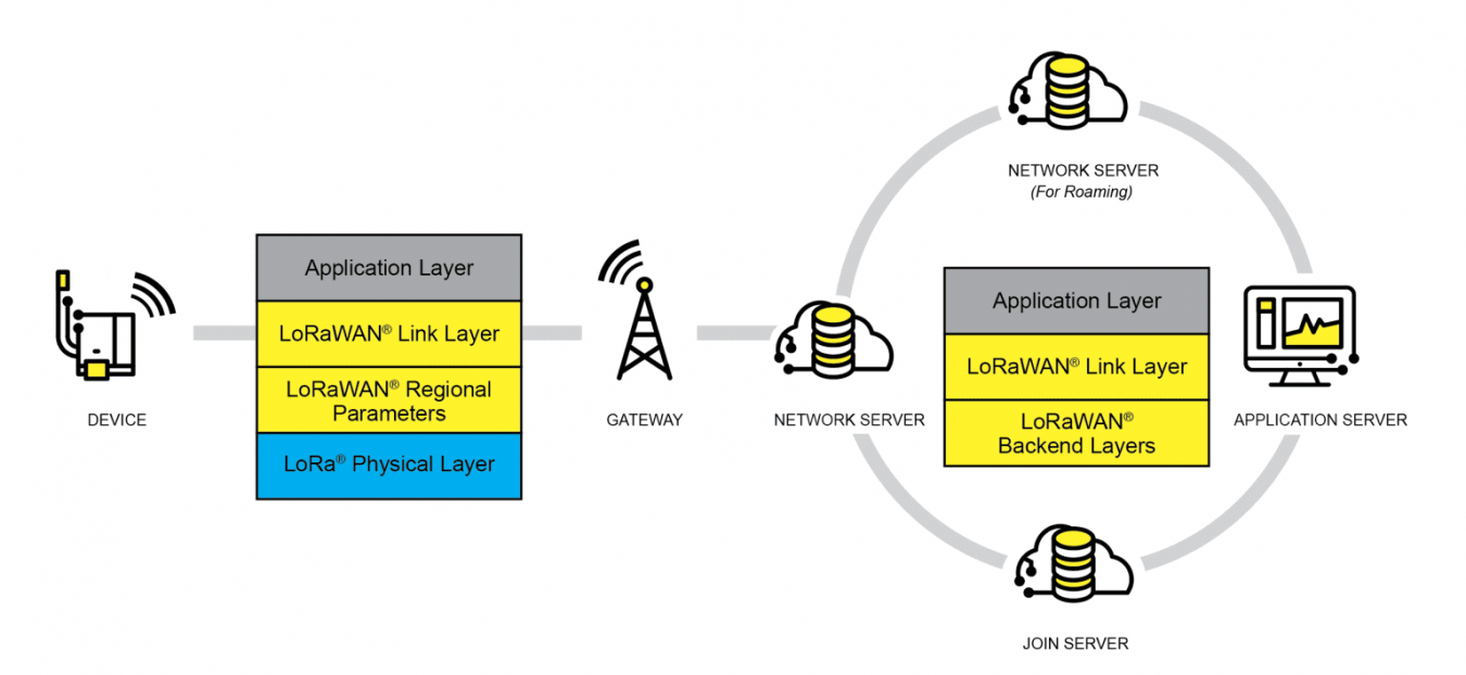
- LoRaWAN is a low-power wide-area network open protocol built on top of LoRa radio modulation technology. It aims to wirelessly connect battery-powered "things" to the Internet in regional, national, or global networks, and is tailored to key IoT requirements such as two-way directional communication, end-to-end security, mobility, and localized services. Among them, the node is wirelessly connected to the Internet and has network access authentication, which is equivalent to establishing an encrypted communication channel between the node and the server, as shown in the following figure of the LoRaWAN protocol layer.
- Class A/B/C three types of node devices in the MAC layer basically cover all the application scenarios of the Internet of Things. The difference among the three lies in the different time slots for node reception and transmission
- In the Modulation layer, EU868, AS430, etc., indicate that different countries use different frequency parameters. For regional parameters, please refer to link
- To achieve LoRaWAN network coverage in a city or other areas, it requires four components: nodes (LoRa nodes RF chips), gateways (or base stations, with LoRa gateways RF chips), servers, and clouds, as shown in the following diagram.
- DEVICE (node device) must first send an access request data packet to the GATEWAY (gateway), which then forwards it to the server. After authentication is successful, it can then normally exchange application data with the server.
- GATEWAY (gateway) can communicate with the server via wired networks, 3/4/5G wireless networks
- The main operators on the server side are TTN, etc. For setting up your own cloud service, please refer to lorawan-stack and chirpstack
Applications
- This application is based on the LoRaWAN official ModemE_application_examples and only demonstrates a basic LoRaWAN Class A application. For other high-level examples, please refer to the official repository for self-porting, including: Certification Application, LoRaWAN Class B Application, LoRaWAN Multicast Class B/C Example and FUOTA Example.
Components Preparation
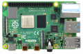
- Raspberry Pi 4 Model B
- Micro SD card / TF card (It is recommended to use an SD/TF card with a capacity greater than 8GB)
- Card reader
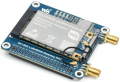
- Gateway Module
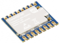
- Node device
- Development board (optional): ESP32, Raspberry Pi, STM32 and Raspberry Pi Pico


Server Setup
- The demo uses ChirpStack as the LoRaWAN network server. Please configure it according to the official installation steps provided for Raspberry Pi.
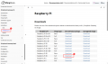
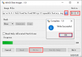
- Download ChirpStack Gateway OS image, unzip it, and then use Win32DiskImager to write the image to the TF card.
- After the writing is completed, please refer to the official documentation for detailed configuration. This Wiki only provides a brief installation process. For detailed information, please see: ChirpStack Gateway OS Getting started.
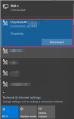
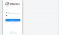
- Insert the TF card into the Raspberry Pi and power it on. Once booted, the computer Wi-Fi will scan for a wireless hotspot named ChirpStackAP-XXXXXX with the password ChirpStackAP. After the connection is successful, visit 192.168.0.1 in the browser to open the ChirpStack management interface, and you can log in for the first time without a password.
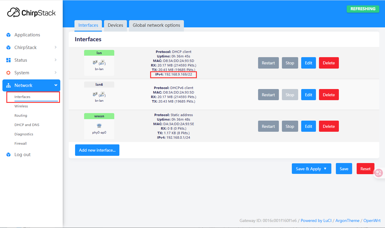
- It can access external networks via Ethernet or Wi-Fi after startup. Here is an example of connecting to Ethernet. If you need to configure Wi-Fi, please refer to: Wi-Fi Configuration. After networking is set up, you can view the current IP address in the Web management interface.
Add Gateway
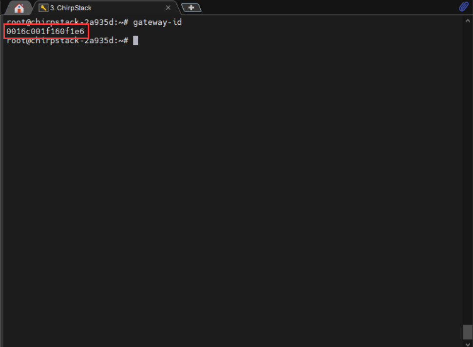
After the server configuration is completed and an IP address is obtained, turn off the Raspberry Pi and power off, then connect the SX1303-868M-LoRaWAN-Gateway-HAT (gateway device) to the Raspberry Pi, and connect the antenna. After powering on the Raspberry Pi, use the obtained IP address to remotely access the device via an SSH tool (such as MobaXterm). The default username is root. After a successful connection, enter the following command in the terminal to get the gateway ID: gateway-id. The system will output the gateway ID of the current device, please note down this ID as it will be needed when adding the gateway later.
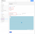
- Access the obtained IP address in your browser and enter the ChirpStack management interface. Click ChirpStack -> Concentratord sequentially and enable the gateway function. Take SX1303 (868 MHz) as an example, configure it as follows, and click "Save and Apply" after completing the configuration:
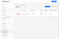
- Enter the application: Applications -> ChirpStack, you need to log in when you enter it for the first time, and the default account and password are admin. After logging in, click Gateways -> Add gateway, fill in the gateway-id obtained earlier on the Add page, and save it. Return to the Gateway page to see if the gateway has been successfully launched.
Add Node
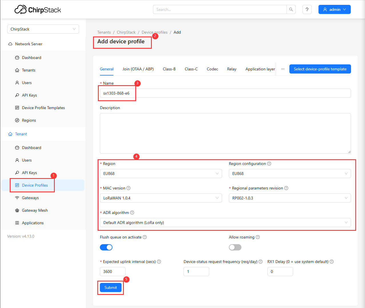
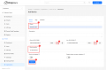
- First, add a device configuration profile in the Web interface: Device Profiles -> Add device profile, configure as shown in the following figure:
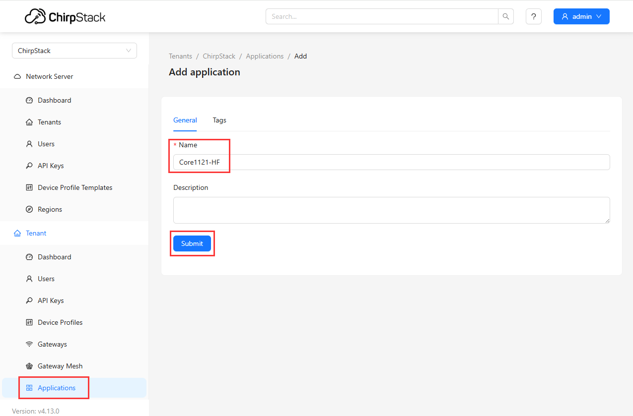
- Then add an application: Applications -> Add application, fill in the relevant information and save:
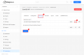
- Then add an end device, click Add device, the relevant information (e.g. DevEUI, AppKey) can be automatically generated by clicking the "Random" button, which will be used in the demo later
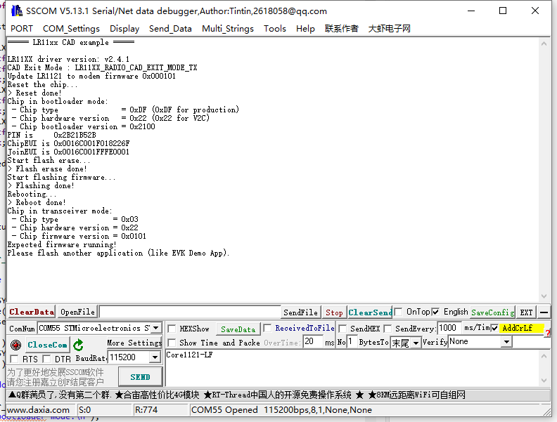
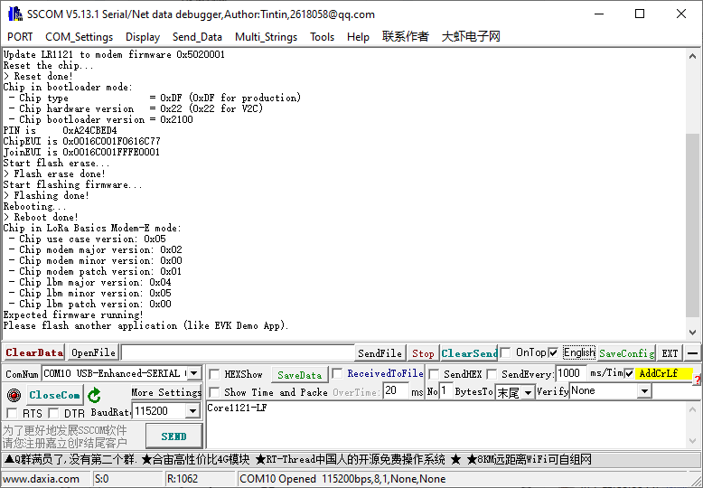
- Note: The Core1121-HF module defaults to Transceiver mode. To run the LoRaWAN protocol, you need to flash the corresponding firmware onto the development board first.
For a demo, refer to the lr1121_firmware_update demo in the Demo, and run lr1121_firmware_update + lr1121_modem_05020001.
- The successful flashing effect is shown in the following figure
After firmware flashing is completed, download the LoRaWAN demo. Open it and enter the directory: ../Core1121-XF-Demo\...\lr1121_LoRaWAN, edit the lorawan_commissioning.h file, and fill in the corresponding positions with the generated EUI and key information. Compile and flash after completion.
- After the flashing is complete, the node will automatically request to join the LoRaWAN network. After joining successfully, the node will periodically send uplink data. Device events and communication status can be viewed through the Web interface:
①. Click Events to view the running status of the node
②. Observe if the joining failed
③. If the join is successful, you will see the network join event
④. Check the data reported by the node
⑤. View the debug information via the serial port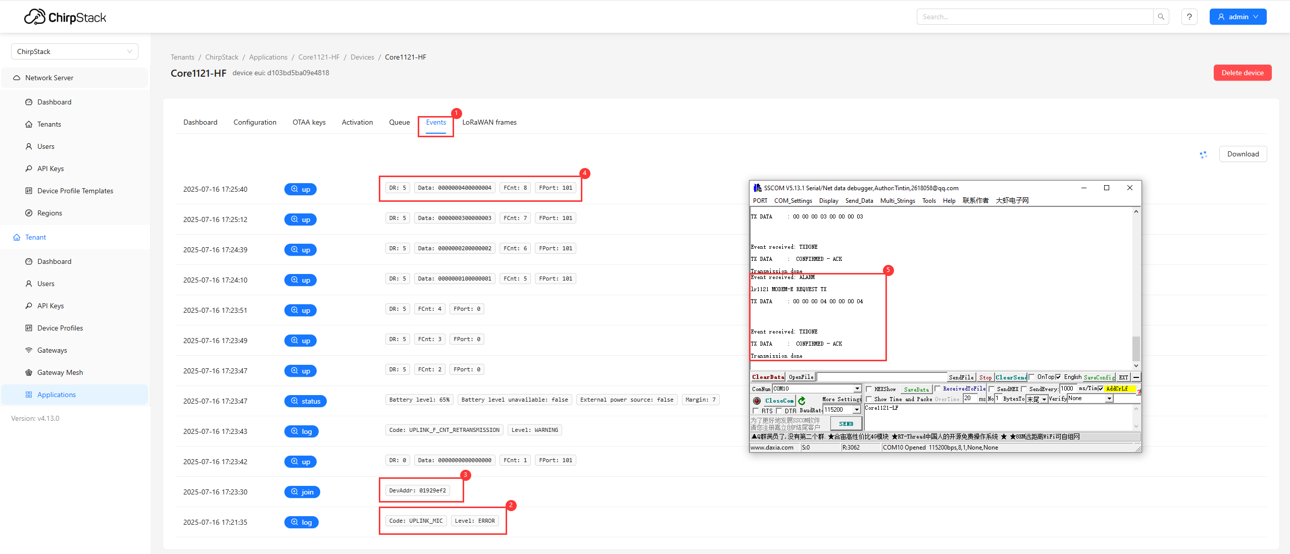
- The server also supports sending data to nodes:
①. Click Queue
②. Enter the hexadecimal data to be sent
③. Click Send
④. The node receives data and prints it via the serial port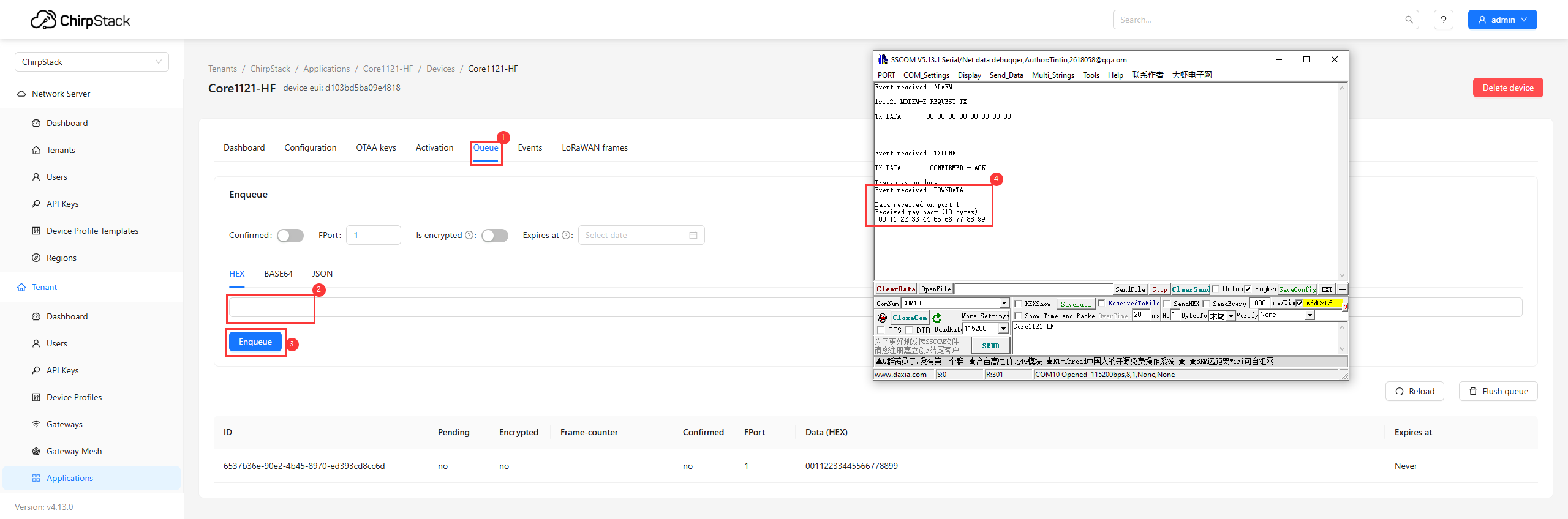
Resources
Documents
Demo
Datasheets
FAQ
Support
Monday-Friday (9:30-6:30) Saturday (9:30-5:30)
Email: services01@spotpear.com