




- sales/support
Google Chat:---
- sales
+86-0755-88291180
- sales01
sales@spotpear.com
- sales02
dragon_manager@163.com
- support
tech-support@spotpear.com
- CEO-Complaints
zhoujie@spotpear.com
- Only Tech-Support
WhatsApp:13246739196
- Purchase/Shipping/Refund
WhatsApp:13424403025
- HOME
- >
- ARTICLES
- >
- Common Moudle
- >
- ESP
ESP32-C5-Touch-LCD-2.8 User Guide
Features
- Utilizes the ESP32-C5-WROOM-1 series module, equipped with a RISC-V 32-bit processor running at up to 240MHz.
- Integrated 384KB SRAM, 320KB ROM, 8MB PSRAM, and 32MB Flash, balancing program execution, GUI rendering, and data storage requirements.
- Integrated 2.4 GHz and 5 GHz dual‑band Wi‑Fi, Bluetooth 5 (LE), and IEEE 802.15.4 (supporting Zigbee 3.0 and Thread) wireless connectivity.
- Onboard battery charging management module, with a reserved 3.7V MX1.25 lithium battery interface for external battery power supply.
- Type‑C interface for power, programming, and debugging, supporting reversible insertion.
- Onboard 2.8inch LCD with 240 × 320 resolution, 262K colors.
- Supports I2C capacitive touch control with interrupt support.
- Exposes UART, I2C, and some I/O interfaces; integrated full‑speed USB serial port.
- Onboard QMI8658 six‑axis sensor, RTC clock sensor, SHTC3 temperature and humidity sensor, and TF card slot.
- Supports flexible clock, multiple power modes, and other precise controls to enable low‑power operation in various scenarios.
- Onboard ES8311 audio codec chip, NS4150B power amplifier chip, microphone, and speaker for voice interaction and audio playback.
- Supports ESP‑IDF / Arduino development environments for quick prototyping and secondary development.
Onboard Resources
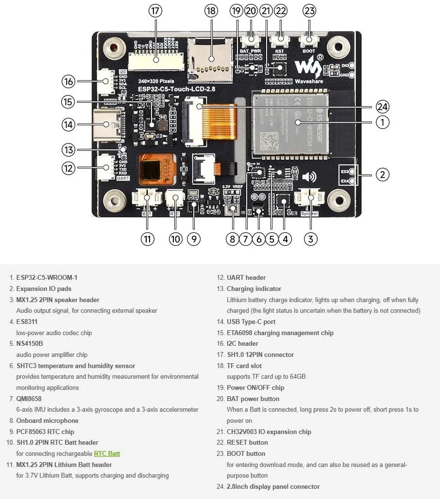
Interface Introduction
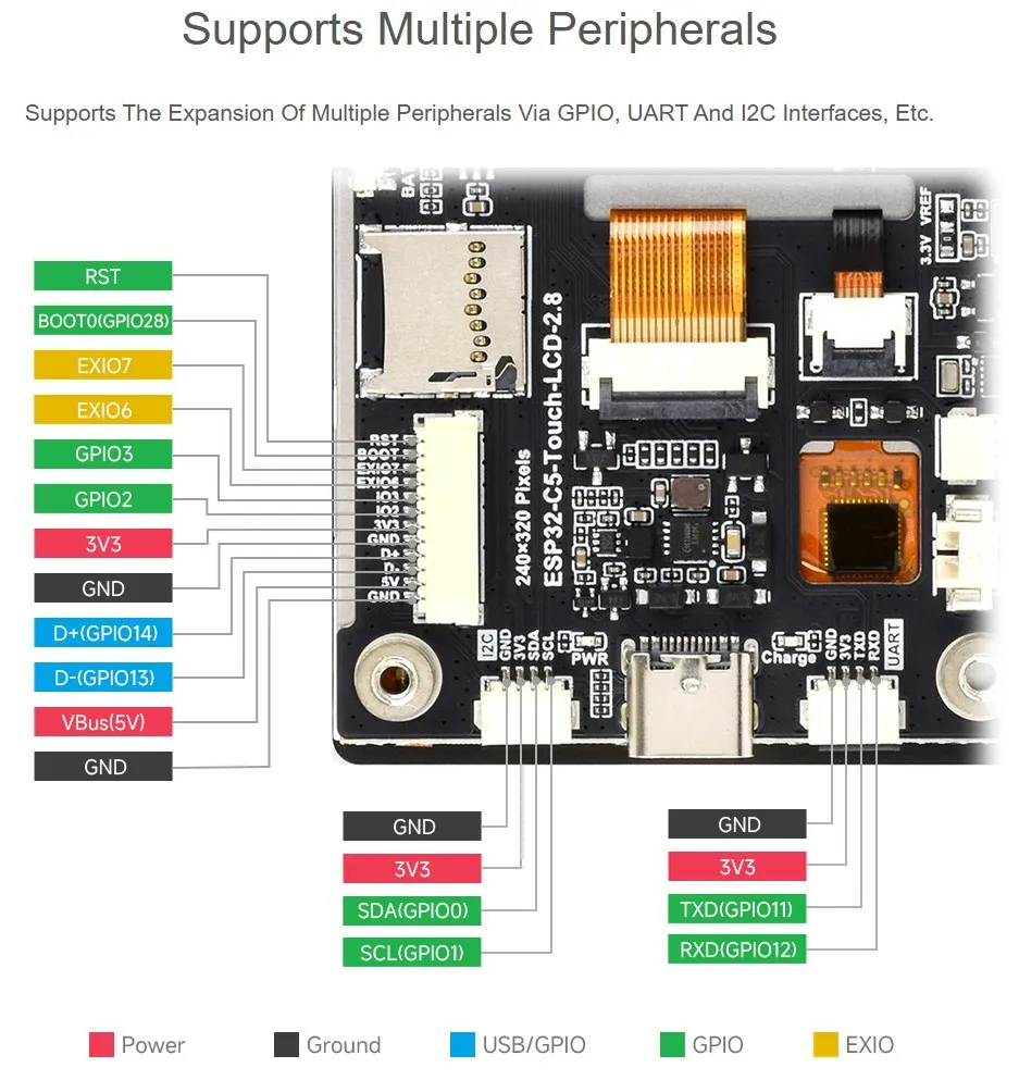
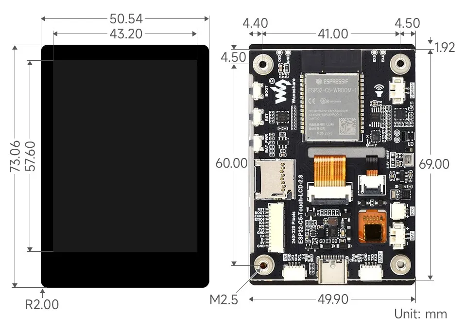
Dimensions
Factory Firmware Instructions
This section provides usage instructions for each functional example in the factory firmware, helping users understand the onboard resources and interface usage of the ESP32-C5-Touch-LCD-2.8. Before running the examples, please prepare the following components:
Required Components
- ESP32-C5-Touch-LCD-2.8 ×1
- TF Card ×1
- Speaker ×1
- Battery ×1
Wi-Fi Configuration
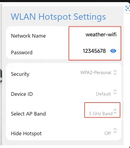
- Before use, turn on a Wi-Fi hotspot. The ESP32-C5 supports dual-band Wi‑Fi; you can choose either the 2.4 GHz or 5 GHz band according to your environment.
- Wi‑Fi SSID:
weather-wifi - Wi‑Fi Password:
12345678 - Band: 2.4 GHz / 5 GHz. Note that some phones may not support 5 GHz hotspots. If you cannot connect, switch to a 2.4 GHz hotspot.
- The Wi‑Fi SSID and password in the factory firmware are fixed. The hotspot you use must match the above configuration; otherwise, the device will not be able to connect.
Precautions
⚠️ USB Download Precautions (Important)
If the port is not recognized, please enter Boot mode:
- Press and hold the BOOT button.
- Connect the USB cable to the computer
- Release the BOOT button.
After the download is complete, power cycle the board to run the program.
BAT_PWR Button Test
- After connecting the battery, the device can be powered directly by the battery and will turn on the screen (controlled by hardware circuitry, not software).
- Long‑press the
BAT_PWRbutton for about 2 seconds to power off. After power‑off, press theBAT_PWRbutton again to power on.
Firmware Download
- The factory firmware is located in the
Firmwaredirectory of the example package.
Example Overview
- The firmware uses the brookesia component to implement an APP‑style interface, including Settings, Photo Album, Music Player, 2048 Game, Weather, Drawing Board, Xiaozhi AI, Gravity Ball, Factory, and other apps.
App Example Introduction
- To exit an app, swipe up from the bottom of the screen.
- Swipe up from the bottom and pause in the middle of the screen to view recently running apps; swipe up again to close and terminate the APP process.
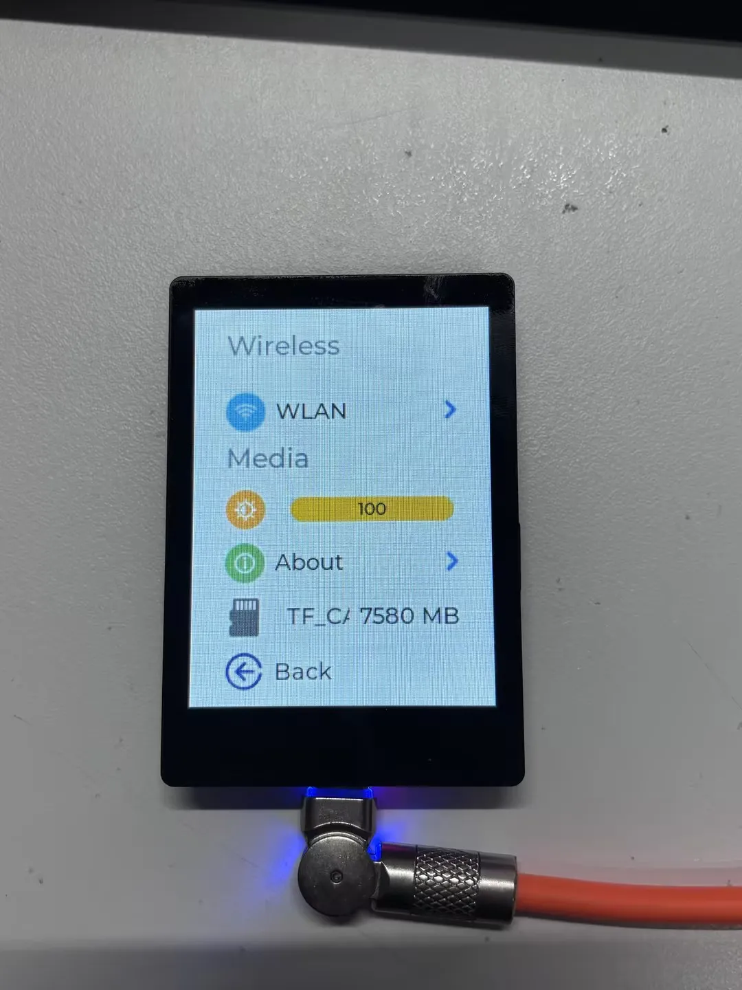
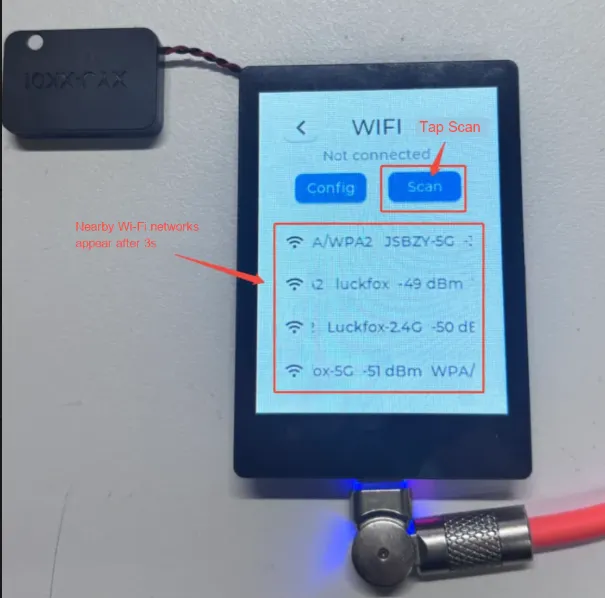
Settings APP
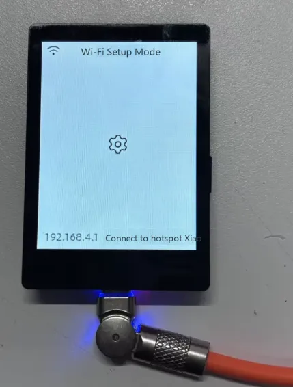
Supports Wi‑Fi scanning and provisioning. Click
wifi configin the Wi‑Fi interface to scan a QR code for network provisioning.Allows adjusting display brightness, viewing TF card size, and checking the MAC address in the product info section.
XiaoZhi AI APP
- Tap the APP to launch the Xiaozhi AI application, which is consistent with the version adapted for the Xiaozhi official website and operates in the same way.
- Long‑press the BOOT button to return to the brookesia interface.
Sensor APP
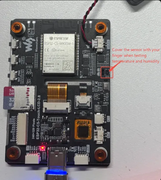
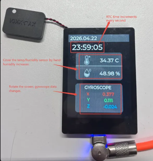
- Displays real‑time data from various sensors.
- When you rotate the board, the gyroscope data changes accordingly; the RTC clock increments by the second.
- When you cover the temperature/humidity sensor with your hand, the humidity value will gradually rise, while the temperature value usually changes little or remains stable.
  |
|---|
Drawing Board APP
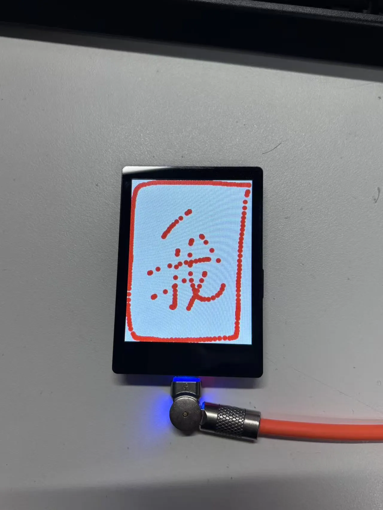
- Allows freehand drawing.
2048 APP
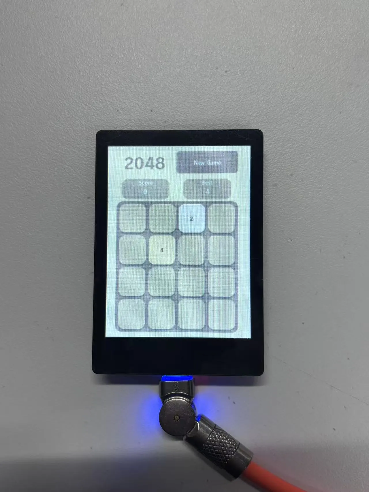
- Displays the current score and the best score in real time, and supports restarting the game with one tap.
MusicPlayer APP
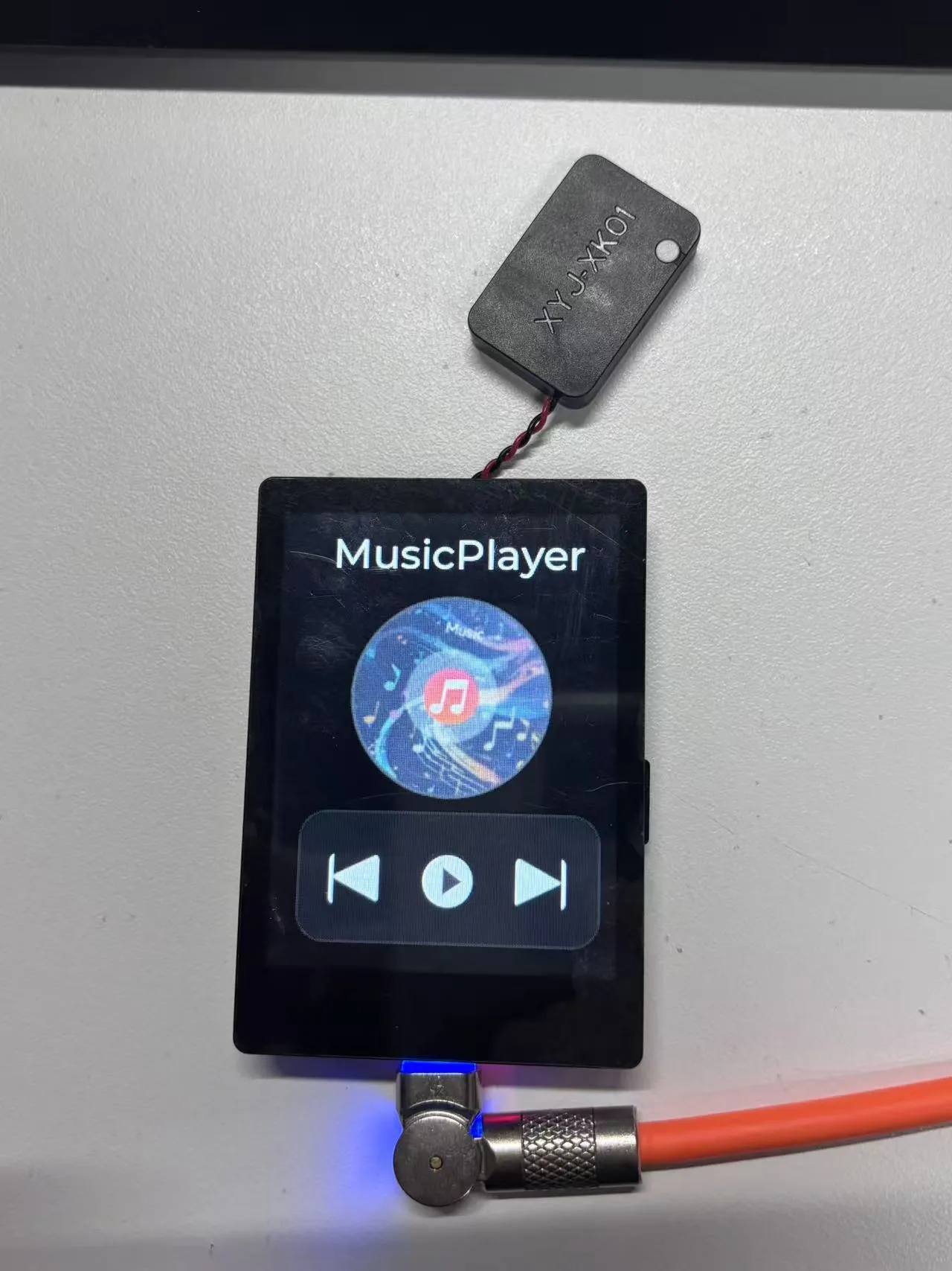
- Supports playing MP3 audio files.
- Before use, connect a speaker to the onboard speaker connector, then tap the play button to play the MP3 file stored in Flash.
- Currently, the example only supports play and pause; switching tracks is not supported.
Weather APP
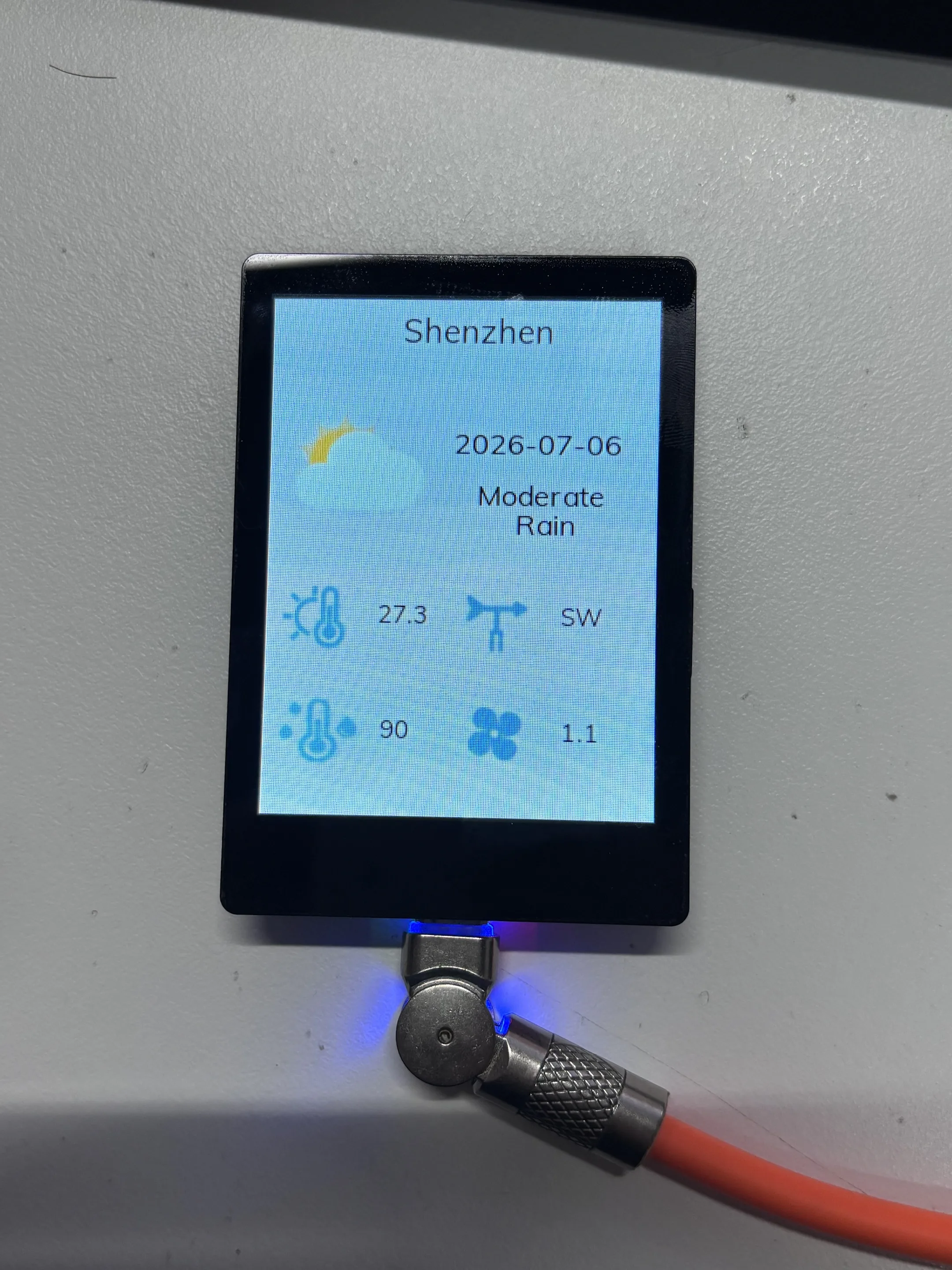
- After the device connects to the network, it will automatically fetch and parse the current day's weather information for Shenzhen within a few seconds.
- For secondary development, modify the ESP‑IDF example
06_wifi_weatheras needed.
Gravity Ball
- This example demonstrates a gravity ball app based on the six‑axis IMU. The ball moves in real time according to the board's tilt angle and orientation changes.
- Before use, place the board flat on a table and wait for the ball to finish loading before picking it up.
- Tap the
BOOTbutton to reset the ball's position.
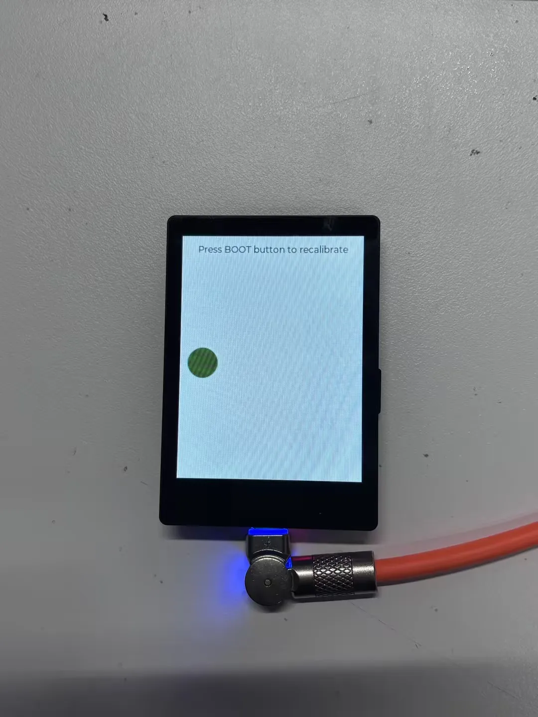
Photo Album APP
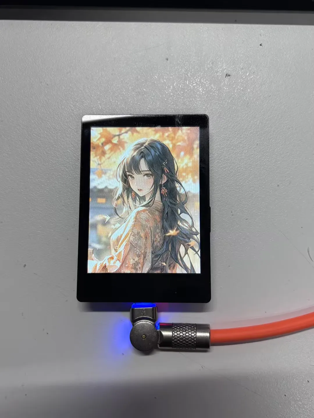
Supports displaying JPG images at 240×320 resolution or lower.
Emulates a digital photo album interface. This APP requires a TF card. Copy the
photofolder from the example programsdcard/directory to the root of the TF card.
Working with Arduino
This chapter includes the following sections, please read as needed:
Before running the examples, please ensure the following conditions are met:
- The ESP32-C5-Touch-LCD-2.8 or ESP32-C5-Touch-LCD-2.8-EN development boards are ready.
- The board is connected to your computer via a USB data cable.
- You have installed the Arduino IDE.
- You have installed the ESP32 Arduino Core. The corresponding example directory is
Arduino-v3.3.10. Please use an Arduino-ESP32 version that matches the example package. - You have downloaded the product example program package.
- To run
04_I2C_pcf85063, install thelib/SensorLibincluded in the example package. To run06_lvgl_demo, install thelib/lvglincluded in the example package.
Arduino Getting Started
New to Arduino ESP32 development and looking for a quick start? We have prepared a comprehensive Getting Started Tutorial for you.
- Section 0: Getting to Know ESP32
- Section 1: Installing and Configuring Arduino IDE
- Section 2: Arduino Basics
- Section 3: Digital Output/Input
- Section 4: Analog Input
- Section 5: Pulse Width Modulation (PWM)
- Section 6: Serial Communication (UART)
- Section 7: I2C Communication
- Section 8: SPI Communication
- Section 9: Wi-Fi Basics
- Section 10: Web Server
- Section 11: Bluetooth
- Section 12: LVGL GUI Development
- Section 13: Comprehensive Project
Note: This tutorial uses the ESP32-S3-Zero as a reference example, and all hardware code is based on its pinout. Before you start, we recommend checking the pinout of your development board to ensure the pin configuration is correct.
Setting Up the Development Environment
1. Installing and Configuring the Arduino IDE
Please refer to the tutorial Installing and Configuring the Arduino IDE to download and install the Arduino IDE.
2. Installing the ESP32 Board Support Package
Install the esp32 by Espressif Systems board support package in the Arduino IDE Board Manager.
The ESP32-C5-Touch-LCD-2.8 uses the ESP32-C5-WROOM-1-N32R8 MCU module, which is a v1.2 chip. Please use version v3.3.10 of the esp32 by Espressif Systems package.
If you use an older version of the ESP32 Arduino core, the board may not be correctly identified, causing serial download failures or preventing the program from being flashed.
ESP32-C5-Touch-LCD-2.8 Board Installation Requirements:
| Board Name | Board Installation Requirement | Version Requirement |
|---|---|---|
| ESP32 by Espressif Systems | "Offline Installation" / "Online Installation" | v3.3.10 |
After installation, select the appropriate ESP32-C5 board in Arduino IDE and select the USB serial port currently connected.
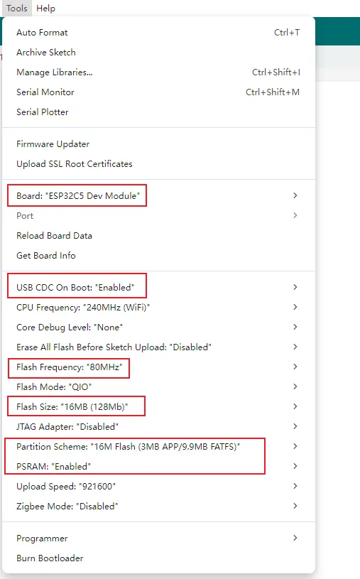
In the Arduino project settings for the ESP32-C5-Touch-LCD-2.8, select ESP32C5 Dev Module as the board.
3. Installing Libraries and Example Dependencies
The Arduino examples for this product minimize external library dependencies, primarily using the built-in capabilities of the Arduino ESP32 core and the source code provided within the example directories. The example package already includes the required libraries in the example/Arduino-v3.3.10/lib directory. You can copy them manually for offline installation, which is suitable for environments without internet access or where the Arduino Library Manager is inconvenient to use.
| Library or File | Purpose | Recommended Version / Source | Examples | Installation Method |
|---|---|---|---|---|
| Arduino ESP32 core | ESP32-C5 board support, download, and basic peripheral interfaces | v3.3.10 | All examples | Arduino IDE Board Manager |
lvgl | LVGL graphics framework | lib/lvgl in example package, LVGL v8.4.0 | 06_lvgl_demo | Offline copy to Arduino libraries directory |
SensorLib / SensorPCF85063.hpp | PCF85063 RTC driver | lib/SensorLib in example package, SensorLib v0.3.1 | 04_I2C_pcf85063 | Offline copy to Arduino libraries directory |
06_lvgl_demo is based on LVGL v8.4.0. Do not replace it with LVGL v9, as interfaces such as lv_disp_drv_t, lv_disp_draw_buf_t, lv_disp_drv_register(), and lv_indev_drv_t are not compatible.
Offline / Manual Installation:
Download and extract the product example program package. Subsequent library installation can be done offline without downloading third-party libraries from the Arduino Library Manager.
Locate the library directories in the example package:
example/Arduino-v3.3.10/lib/lvglexample/Arduino-v3.3.10/lib/SensorLibCopy the
lvglandSensorLibfolders to your Arduino libraries directory.The default libraries directory on Windows is usually:
C:\Users\<username>\Documents\Arduino\librariesYou can also check the
Sketchbook locationviaFile > Preferencesin the Arduino IDE; thelibrariesfolder under that path is the libraries directory.Restart Arduino IDE after installation, then open the examples to compile.
Installation Verification:
- The
lvglandSensorLibdirectories can be seen underDocuments\Arduino\libraries. Documents\Arduino\libraries\SensorLib\library.propertiesshowsversion=0.3.1.Documents\Arduino\libraries\lvgl\library.propertiesshowsversion=8.4.0.- The
lv_conf.hfile in the06_lvgl_demodirectory must remain in the example directory. Do not move it to the global Arduino libraries directory or delete it. - Do not keep multiple different versions of
lvglorSensorLibsimultaneously to avoid header file conflicts. - If compiling
04_I2C_pcf85063fails withSensorPCF85063.hppnot found, confirm thatlib/SensorLibfrom the example package has been copied to the Arduino libraries directory.
4. Arduino Project Parameter Settings
- Open Arduino IDE.
- Install
esp32 by Espressif Systems v3.3.10. - In
Tools>Board, selectESP32C5 Dev Module. - Select the USB serial port currently connected.
- Open the corresponding
.inofile inexample/Arduino-v3.3.10to compile and flash.
When using arduino-cli, refer to the following commands:
arduino-cli core install esp32:esp32@3.3.10
arduino-cli compile --fqbn esp32:esp32:esp32c5 example/Arduino-v3.3.10/06_lvgl_demo
Example
The Arduino examples are located in the example/Arduino-v3.3.10 directory of the example package. Each example has been adapted to the actual hardware connections of the ESP32-C5-Touch-LCD-2.8.
1. Onboard Resources
| Feature | Device or Interface | Pins or Notes |
|---|---|---|
| LCD | ST7789, SPI, 240 x 320, RGB565 | SCLK GPIO6, MOSI GPIO7, DC GPIO9, CS GPIO10 |
| LCD Reset | CH32V003 I/O Expander | EXIO1 |
| LCD Backlight | CH32V003 PWM | CH32 PWM |
| Touch | CST3530, I2C | SDA GPIO0, SCL GPIO1, INT GPIO5 |
| Touch Reset | CH32V003 I/O Expander | EXIO0 |
| I/O Expander | CH32V003, I2C address 0x24 | SDA GPIO0, SCL GPIO1 |
| 6‑axis IMU | QMI8658, I2C address 0x6B | SDA GPIO0, SCL GPIO1 |
| RTC | PCF85063, I2C address 0x51 | SDA GPIO0, SCL GPIO1 |
| Temp/Humidity Sensor | SHTC3, I2C address 0x70 | SDA GPIO0, SCL GPIO1 |
| TF | SDSPI | SCLK GPIO6, MOSI GPIO7, MISO GPIO8, CS GPIO23 |
Display, touch, backlight, reset, and sensor pins have already been adapted to the product hardware connections in the examples. For routine secondary development, we recommend focusing on application‑layer and UI logic modifications. Do not change the underlying pin definitions unless you are porting the code to a different board or modifying the hardware connections.
2. Example List
| Example Directory | Basic Description | Main Test Content |
|---|---|---|
| 01_exio | Tests the onboard CH32V003 I/O expander, toggles EXIO0~EXIO7 output levels cyclically | I/O expansion, I2C bus |
| 02_I2C_qmi8658 | Reads QMI8658 6‑axis sensor data and outputs accelerometer and gyroscope data over serial | IMU, I2C bus |
| 03_SD_Card | Mounts a TF card via SDSPI, prints TF card info and capacity, and provides file read/write interfaces | TF, SDSPI |
| 04_I2C_pcf85063 | Initializes the PCF85063 RTC, sets a test time, and periodically prints RTC time over serial | RTC, I2C bus |
| 05_shtc3 | Reads SHTC3 temperature and humidity sensor ID, temperature, and humidity, and outputs over serial | Temp/Humidity sensor, CRC check |
| 06_lvgl_demo | Displays a touch example UI using ST7789, CST3530, and LVGL v8.4.0 | LCD, backlight, touch, LVGL |
3. Directory Structure
The current Arduino examples directory contains the following projects:
example/Arduino-v3.3.10
|-- 01_exio
|-- 02_I2C_qmi8658
|-- 03_SD_Card
|-- 04_I2C_pcf85063
|-- 05_shtc3
|-- 06_lvgl_demo
`-- lib
    |-- SensorLib
    `-- lvgl
Each subdirectory is an independent Arduino example. To open an example, open the .ino file inside that directory, for example:
example/Arduino-v3.3.10/01_exio/01_exio.ino
lib/SensorLib is the RTC driver library used by 04_I2C_pcf85063 (SensorLib v0.3.1). lib/lvgl is the LVGL v8.4.0 library used by 06_lvgl_demo. Before compiling 04_I2C_pcf85063, you need to copy SensorLib at minimum. Before compiling 06_lvgl_demo, you need to copy lvgl at minimum.
4. Recommended First‑Run Order
It is recommended to run the examples in the following order:
01_exio
  -> 02_I2C_qmi8658
  -> 03_SD_Card
  -> 04_I2C_pcf85063
  -> 05_shtc3
  -> 06_lvgl_demo
- Start with
01_exioto verify the CH32V003 I/O expander and I2C bus. LCD reset, touch reset, and backlight are all related to CH32V003, so confirm this example works first. - Then use
02_I2C_qmi8658to verify 6‑axis sensor data reading. - Then use
03_SD_Cardto verify the TF card and SDSPI. - Then use
04_I2C_pcf85063to verify RTC time setting and reading. - Then use
05_shtc3to verify SHTC3 temperature/humidity reading and CRC checking. - Finally, run
06_lvgl_demoto verify LCD, backlight, touch, and LVGL all together.
5. Usage Notes
- The Arduino example directory is
example/Arduino-v3.3.10. Do not mix it with the ESP‑IDF example directory. - This product uses a shared I2C bus:
SDA GPIO0,SCL GPIO1. CH32V003, QMI8658, PCF85063, SHTC3, and CST3530 are all on this I2C bus. - Insert a FAT or FAT32‑formatted TF card before running
03_SD_Card. 04_I2C_pcf85063writes a fixed test time on every power‑up by default. To enable continuous RTC time‑keeping, comment outi2c_rtc_setTime().06_lvgl_demohas already been adapted for ST7789 display and CST3530 touch. No additional GFX display library or third‑party touch library is required.- If you copy code from other projects, pay special attention to the LCD and touch reset pins:
LCD_RST = CH32 EXIO1,TP_RST = CH32 EXIO0. - For compilation, display, touch, I2C address, and other troubleshooting, refer to the FAQ.
6. Example Details
01_exio
Function Description
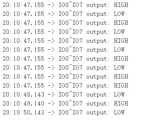
This example verifies communication with the onboard CH32V003 I/O expander. CH32V003 communicates with the ESP32‑C5 via I2C at address 0x24. The example configures EXIO0~EXIO7 as outputs and toggles them every second.
CH32V003 is pre‑programmed with firmware at the factory; no separate CH32 firmware flashing is required.
Code Entry
01_exio/01_exio.ino
01_exio/io_extension.cpp
01_exio/io_extension.h
Recommended key code sections:
| Code | Purpose |
|---|---|
Wire.begin(I2C_SDA, I2C_SCL) | Initializes I2C with SDA GPIO0, SCL GPIO1 |
IO_EXTENSION_ADDR | CH32V003 I2C, default 0x24 |
IO_EXTENSION_Init(Wire) | Initializes the I/O expander |
IO_EXTENSION_IO_Mode(0xFF) | Configures EXIO0~EXIO7 as outputs |
IO_EXTENSION_Output() | Sets the output level of a specified EXIO pin |
Expected Behavior
- Serial log output should look similar to this:
Troubleshooting
| Symptom | Possible Cause | Action |
|---|---|---|
Serial shows IO extension not found at 0x24 | I2C communication failure | Confirm SDA GPIO0, SCL GPIO1 and ensure the board is powered |
| LCD or touch malfunctions later | CH32V003 not communicating | First ensure 01_exio works, then debug display and touch |
| Need to re‑flash CH32V003 firmware | Not required | CH32V003 is pre‑programmed at the factory; no action needed for normal use |
02_I2C_qmi8658
Function Description
This example reads the onboard QMI8658 6‑axis sensor. After initializing I2C, the program creates a qmi8658c_example task that reads accelerometer and gyroscope data every second and outputs it over serial.
Code Entry
02_I2C_qmi8658/02_I2C_qmi8658.ino
02_I2C_qmi8658/i2c_bsp.cpp
02_I2C_qmi8658/qmi8658c.cpp
Recommended key code sections:
| Code | Purpose |
|---|---|
I2C_master_Init() | Initializes I2C with SDA GPIO0, SCL GPIO1, 400 kHz |
QMI8658_SLAVE_ADDR_H | QMI8658 I2C address, default 0x6B |
qmi8658_init() | Initializes QMI8658 |
qmi8658_read_xyz() | Reads accelerometer and gyroscope data |
Expected Behavior
- Serial outputs QMI8658 initialization information, followed by sensor data every second.
- When you gently tilt or rotate the board, the accelerometer and gyroscope values change accordingly. The log should look like this:

Troubleshooting
| Symptom | Possible Cause | Action |
|---|---|---|
Serial shows qmi8658_init fail | QMI8658 I2C communication failure | Confirm I2C pins are GPIO0/GPIO1; run 01_exio or 05_shtc3 first to verify I2C |
| Data remains unchanged | Board is stationary or task not running | Gently rotate the board and confirm the serial baud rate is 115200 |
| Compilation errors related to I2C interfaces | Arduino ESP32 core version mismatch | Use esp32 by Espressif Systems v3.3.10 |
03_SD_Card
Function Description
This example verifies the TF card interface. It uses SDSPI mode to mount the TF card at /sd_card by default, and prints TF card information and capacity upon success.
Code Entry
03_SD_Card/03_SD_Card.ino
03_SD_Card/sd_card_bsp.cpp
03_SD_Card/sd_card_bsp.h
Recommended key code sections:
| Code | Purpose |
|---|---|
PIN_NUM_CLK | TF SCLK, GPIO6 |
PIN_NUM_MOSI | TF MOSI, GPIO7 |
PIN_NUM_MISO | TF MISO, GPIO8 |
PIN_NUM_CS | TF CS, GPIO23 |
SD_card_Init() | Initializes SPI bus and mounts TF card |
s_example_write_file() / s_example_read_file() | Example file write/read interfaces |
Expected Behavior
- With a FAT32‑formatted TF card inserted, the serial prints TF card type, capacity, and other information. The log should look like this:

Troubleshooting
| Symptom | Possible Cause | Action |
|---|---|---|
| TF card mount fails | No card inserted, invalid format, or poor contact | Use a FAT/FAT32 TF card, re‑insert, and retest |
| Compilation errors related to SDMMC/SDSPI interfaces | Arduino ESP32 core version mismatch | Use v3.3.10 |
| File read/write fails | Mount failure or incorrect path | Confirm SD_card_Init() prints card info successfully |
04_I2C_pcf85063
Function Description
This example verifies the onboard PCF85063 RTC. The program initializes the RTC and calls the following in setup():
i2c_rtc_setTime(2025, 9, 9, 14, 51, 30);
It then creates an i2c_rtc_loop_task task that reads and prints RTC time every second.
Code Entry
04_I2C_pcf85063/04_I2C_pcf85063.ino
04_I2C_pcf85063/rtc_bsp.cpp
04_I2C_pcf85063/rtc_bsp.h
Recommended key code sections:
| Code | Purpose |
|---|---|
rtc.begin(Wire, SENSOR_SDA, SENSOR_SCL) | Initializes PCF85063 with SDA GPIO0, SCL GPIO1 |
i2c_rtc_setTime() | Sets RTC time |
i2c_rtc_get() | Reads RTC time structure |
i2c_rtc_loop_task() | Periodically reads and prints RTC time over serial |
Expected Behavior
- Serial outputs RTC time every second. The log should look like this:

Since the example writes a fixed test time on every power‑up, if you want to verify continuous RTC time‑keeping, comment out or delete i2c_rtc_setTime().
Troubleshooting
| Symptom | Possible Cause | Action |
|---|---|---|
Compilation fails with SensorPCF85063.hpp not found | Missing SensorLib dependency | Copy example/Arduino-v3.3.10/lib/SensorLib to Arduino libraries directory |
Serial shows Failed to find PCF85063 | RTC I2C communication failure | Confirm I2C pins are GPIO0/GPIO1; test other I2C examples first |
| Time always resets to fixed value on power‑up | Example actively writes test time | Comment out or delete i2c_rtc_setTime() and retest |
05_shtc3
Function Description
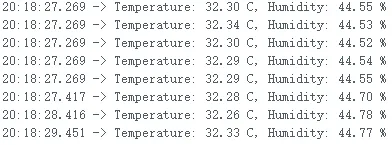
This example reads the onboard SHTC3 temperature and humidity sensor. The program uses Wire to send SHTC3 commands, wakes the sensor, reads its ID, performs a soft reset, and reads temperature and humidity every second in loop().
CRC checking is implemented to prevent invalid data from being treated as normal temperature/humidity readings.
Code Entry
05_shtc3/05_shtc3.ino
Recommended key code sections:
| Code | Purpose |
|---|---|
SHTC3_ADDR | SHTC3 I2C address, default 0x70 |
SHTC3_CMD_READ_ID | Reads sensor ID |
SHTC3_CMD_MEASURE_T_RH | Triggers temperature/humidity measurement |
shtc3Crc() | CRC check for SHTC3 data |
readShtc3() | Reads and converts temperature and humidity |
Expected Behavior
- Serial outputs the SHTC3 ID first, then periodically outputs temperature and humidity. The log should look like this:
Troubleshooting
| Symptom | Possible Cause | Action |
|---|---|---|
Serial shows SHTC3 not found | I2C communication failure | Confirm I2C pins are GPIO0/GPIO1 and ensure the board is powered |
Serial shows Failed to read SHTC3 | CRC failure or sensor not responding | Keep power stable, power cycle, and retest |
| Occasional abnormal temperature/humidity values | Invalid I2C data | The example includes CRC checking; use data that passes the check |
06_lvgl_demo
Function Description
This example verifies LCD display, backlight, touch, and LVGL basic UI. It does not depend on the GFX display library. The LCD driver is adapted from the ST7789 example into Display_ST7789, the touch driver is adapted from the CST3530 example into Touch_CST3530, and CH32V003 I/O expansion, LCD reset, touch reset, and backlight control are consolidated in Board_IO.
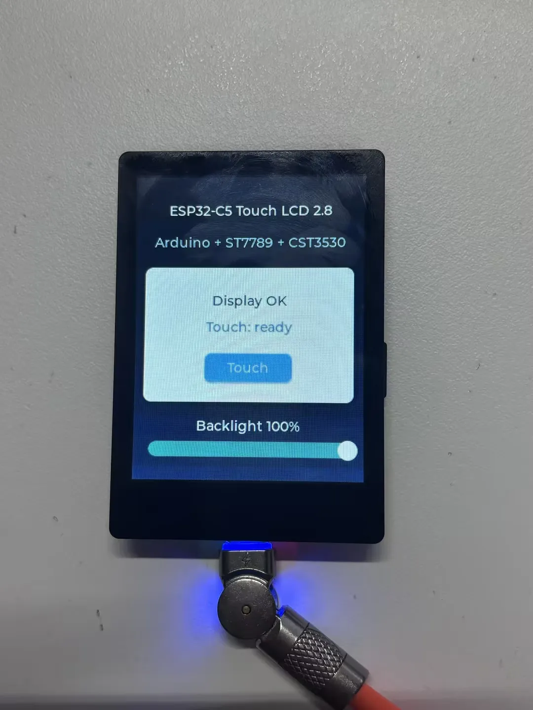
The UI displays the board name, display status, touch status, touch coordinates, and backlight brightness.
Code Entry
06_lvgl_demo/06_lvgl_demo.ino
06_lvgl_demo/Board_IO.cpp
06_lvgl_demo/Board_IO.h
06_lvgl_demo/Display_ST7789.cpp
06_lvgl_demo/Display_ST7789.h
06_lvgl_demo/Touch_CST3530.cpp
06_lvgl_demo/Touch_CST3530.h
06_lvgl_demo/lv_conf.h
Recommended key code sections:
| Code | Purpose |
|---|---|
LCD_WIDTH / LCD_HEIGHT | LCD resolution, 240 x 320 |
EXAMPLE_PIN_NUM_SCLK / EXAMPLE_PIN_NUM_MOSI | LCD SPI pins, GPIO6/GPIO7 |
EXAMPLE_PIN_NUM_LCD_DC / EXAMPLE_PIN_NUM_LCD_CS | LCD DC/CS pins, GPIO9/GPIO10 |
BOARD_LCD_RST_EXIO | LCD reset, CH32V003 EXIO1 |
BOARD_TP_RST_EXIO | Touch reset, CH32V003 EXIO0 |
CST3530_ADDR | CST3530 I2C address, default 0x58 |
LCD_Init() | Initializes SPI bus and ST7789 panel |
TOUCH2_Init() | Initializes CST3530 touch |
create_demo_ui() | Creates LVGL example UI |
Expected Behavior
The LCD displays the ESP32-C5 Touch LCD 2.8 example UI. When you touch the screen, the UI updates with touch coordinates. Dragging the progress bar at the bottom adjusts backlight brightness. Serial output shows:
ESP32-C5-Touch-LCD-2.8 Arduino LVGL demo
Touch controller CST3530 initialized
LVGL demo started
If touch is not recognized, the UI displays Touch: not found.
Troubleshooting
| Symptom | Possible Cause | Action |
|---|---|---|
Compilation fails with lvgl.h not found | LVGL not installed from example package | Copy example/Arduino-v3.3.10/lib/lvgl to Arduino libraries directory |
Compilation errors related to lv_disp_drv_t / lv_indev_drv_t | LVGL v9 used | Remove the incorrect version and use LVGL v8.4.0 from the example package |
| Screen does not light up | CH32V003, LCD reset, backlight, or ST7789 initialization failure | Run 01_exio first to confirm CH32V003 is working; then restore original pin configuration in 06_lvgl_demo |
| Touch does not respond | CST3530 not detected or touch reset issue | Confirm I2C uses GPIO0/GPIO1, touch interrupt is GPIO5, and touch reset is CH32 EXIO0 |
| Display colors are incorrect | RGB565 byte order or color depth modified | Confirm lv_conf.h uses LV_COLOR_DEPTH 16 and keep the LV_COLOR_16_SWAP configuration from the example |
XiaoZhi AI Application Tutorial
XiaozhiAI (XiaoZhi AI) is an open-source AI voice chatbot project based on the ESP32 development board, aiming to bring the general intelligence of large language models (LLMs) to edge devices. It provides a software-hardware integrated solution supporting full-duplex voice conversations and IoT device control, dedicated to assisting developers in building highly customized physical AI agents quickly and at low cost.
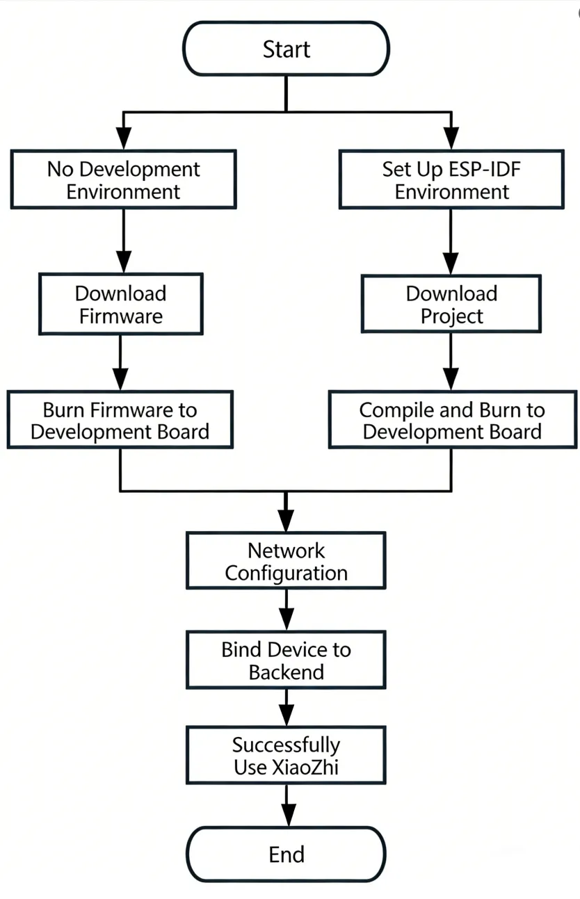
This article demonstrates how to flash firmware for Waveshare ESP32 development boards that support XiaoZhi AI, covering two methods: flashing without a development environment (directly flashing precompiled firmware) and flashing with a development environment (compiling from source and flashing).
0. Firmware Flashing Process Reference
This section uses the ESP32-S3-Touch-AMOLED-1.8 development board as an example. The steps are similar for other development boards.
Please first confirm that your hardware is listed in the XiaoZhi AI Supported Products List.
1. Flashing Without a Development Environment
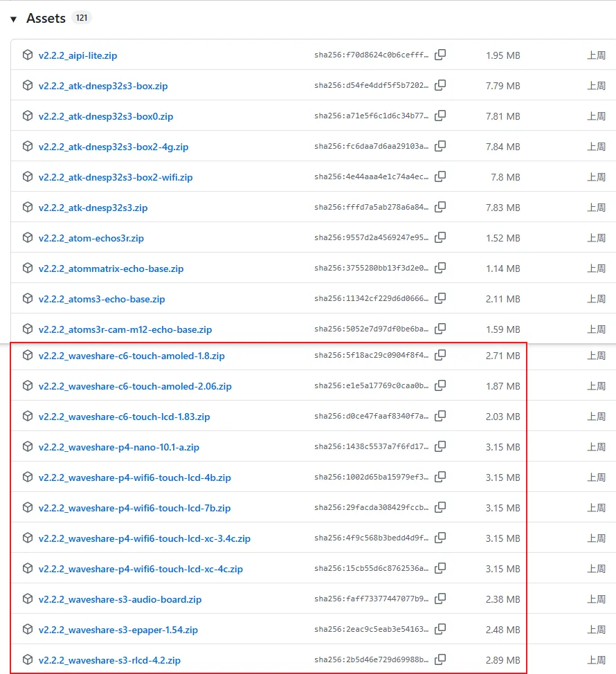
1.1 Download Firmware from XiaoZhi Official GitHub
Visit the XiaoZhi GitHub to download the firmware file for your device. Click Assets to expand the full file list:
Refer to the Flash Firmware Flashing and Erasing Tutorial to complete the firmware flashing.
1.2 Download Firmware from Waveshare GitHub
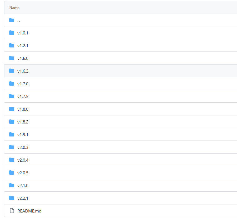
This repository aggregates firmware for Waveshare ESP32 development boards that support XiaoZhi AI. All firmware has been tested and verified on the corresponding boards, making it convenient for users to find and download. Firmware versions may be updated slightly later than the official XiaoZhi repository.
Visit the Waveshare GitHub repository and download the appropriate firmware version for your needs:
Refer to the Flash Firmware Flashing and Erasing Tutorial to complete the firmware flashing.
2. Flashing with ESP-IDF Environment
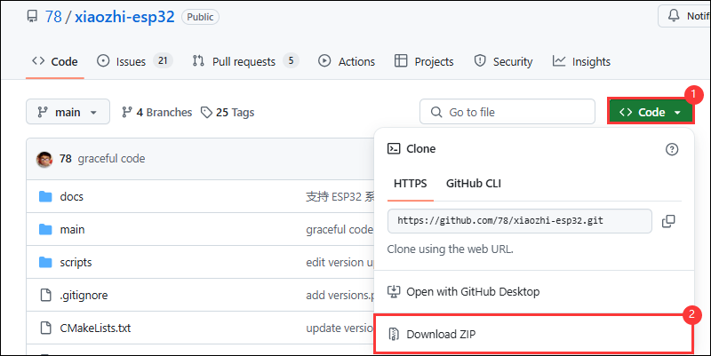
2.1 Download the Project from XiaoZhi GitHub
Visit the XiaoZhi AI Chatbot repository to download the complete project code:
2.2 Environment Setup
Refer to the ESP-IDF Environment Setup Tutorial to configure the development environment.
2.3 Configuration and Compilation
Click
 to select the target device. Choose the chip model corresponding to your development board (e.g.,
 esp32s3):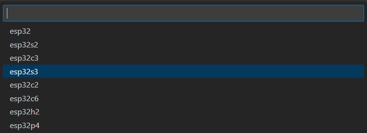 TIP
TIPWhen setting the target device, ESP-IDF will automatically configure the corresponding toolchain and libraries. This process may take some time, please be patient. For more details, please refer to the Official Documentation.
Click
 to open the ESP-IDF terminal, then execute the command
 idf.py menuconfigto enter the configuration interface. Select Xiaozhi Assistant: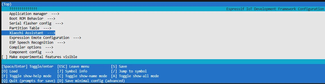
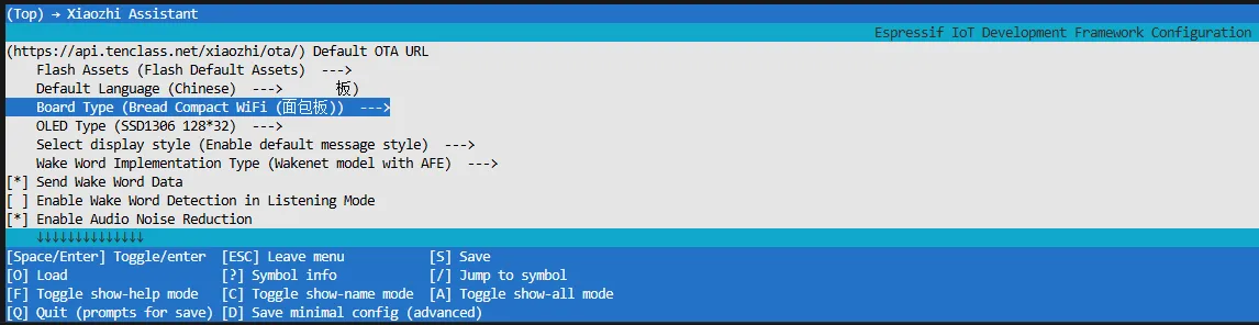
Select Board Type to choose the development board type:
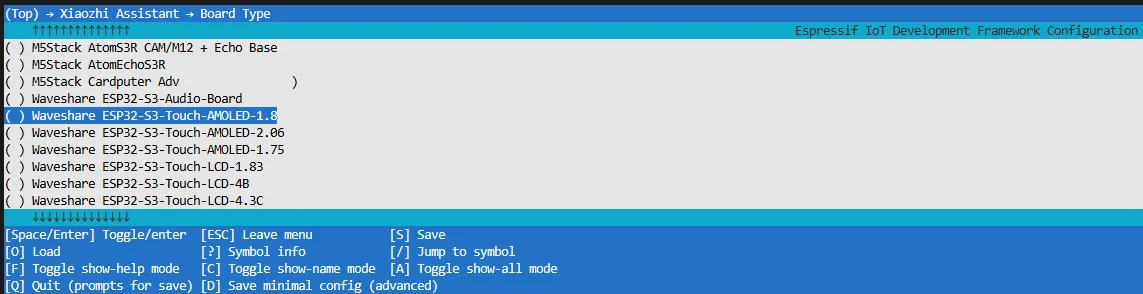
Choose the product model corresponding to your development board:
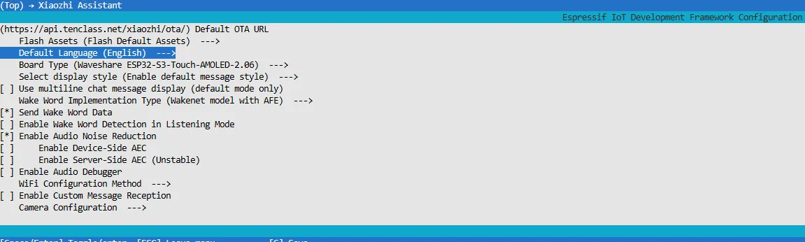
Choose XiaoZhi-AI default display language:
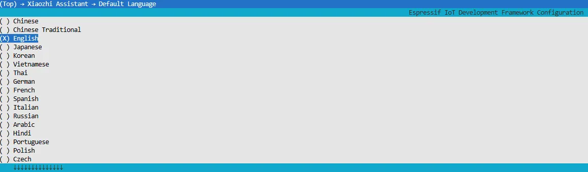
Press the S key to save the configuration and exit. Then click the
 to automatically complete compilation, flashing, and serial monitoring.
2.4 Start Network Provisioning
Connect your phone or computer to the device's Wi-Fi hotspot: Xiaozhi-xxxxxx. After successful connection, the configuration page should automatically pop up. If not, manually open a browser and visit
http://192.168.4.1.On the network configuration page, select the Wi-Fi name you want to connect to (only 2.4G band is supported; to connect to an iPhone hotspot, enable Max Compatibility in your phone's system settings). The SSID will be auto-filled. Enter the password and click Connect to start connecting:

2.5 Add a New Device to the Management Console
Ensure the device has successfully connected to the Internet. The device will then broadcast a 6-digit device verification code (you can wake the device again to replay the code).
Visit the XiaoZhi AI Console. If you haven't registered, complete the registration and log in:
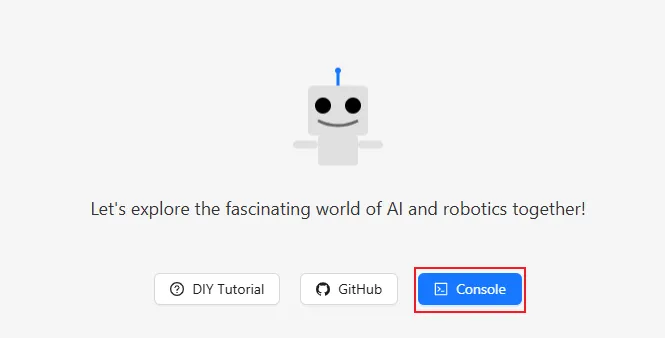

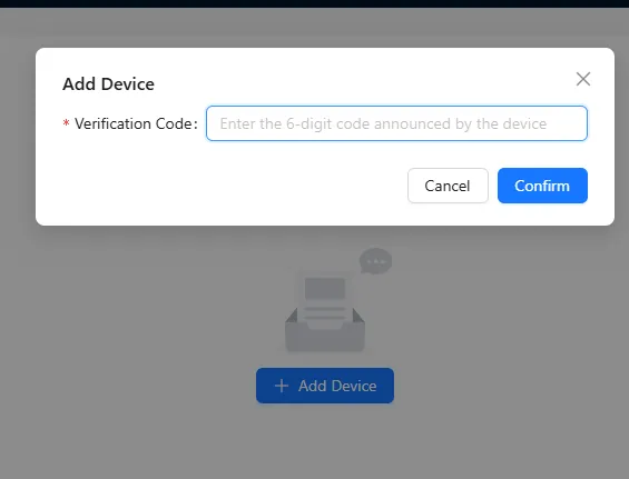
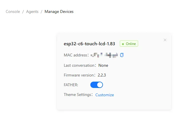
Enter the 6-digit verification code. The device will automatically activate and appear on the Device Management page, ready for normal use.
Say the wake word "Hello XiaoZhi" to wake the device and start voice conversations.
ESP32-S3-Touch-AMOLED-1.8 Button Instructions:
- BOOT button: Press to wake XiaoZhi
- PWR button: Short press to power on; long press for more than 6 seconds to power off
3. XiaoZhi Resources
Working with ESP-IDF
This chapter includes the following sections, please read as needed:
ESP-IDF Getting Started
New to ESP32 ESP-IDF development and looking to get started quickly? We have prepared a general Getting Started Tutorial for you.
- Section 1: Environment Setup
- Section 2: Running Examples
- Section 3: Creating a Project
- Section 4: Using Components
- Section 5: Debugging
- Section 6: FreeRTOS
- Section 7: Peripherals
- Section 8: Wi-Fi Programming
- Section 9: BLE Programming
Please Note: This tutorial uses the ESP32-S3-Zero as a teaching example, and all hardware code is based on its pinout. Before you start, it is recommended that you check the pinout of your development board to ensure the pin configuration is correct.
Setting Up the Development Environment
Please refer to Install ESP-IDF Development Environment.
The ESP32-C5-Touch-LCD-2.8 examples require ESP-IDF v5.5.4.
The following guide uses Windows as an example, demonstrating development using VS Code + the ESP-IDF extension. macOS and Linux users should refer to the official documentation.
The screenshots in this section use ESP-IDF V5.5.2 as an example. When installing, please select the ESP-IDF version that matches your board's example.
Install the ESP-IDF Development Environment
Download the installation manager from the ESP-IDF Installation Manager page. This is Espressif's latest cross-platform installer. The following steps demonstrate how to use its offline installation feature.
Click the Offline Installer tab on the page, then select Windows as the operating system and the ESP-IDF version you need (the version shown in the screenshot is for reference only — choose the version that fits your actual needs).
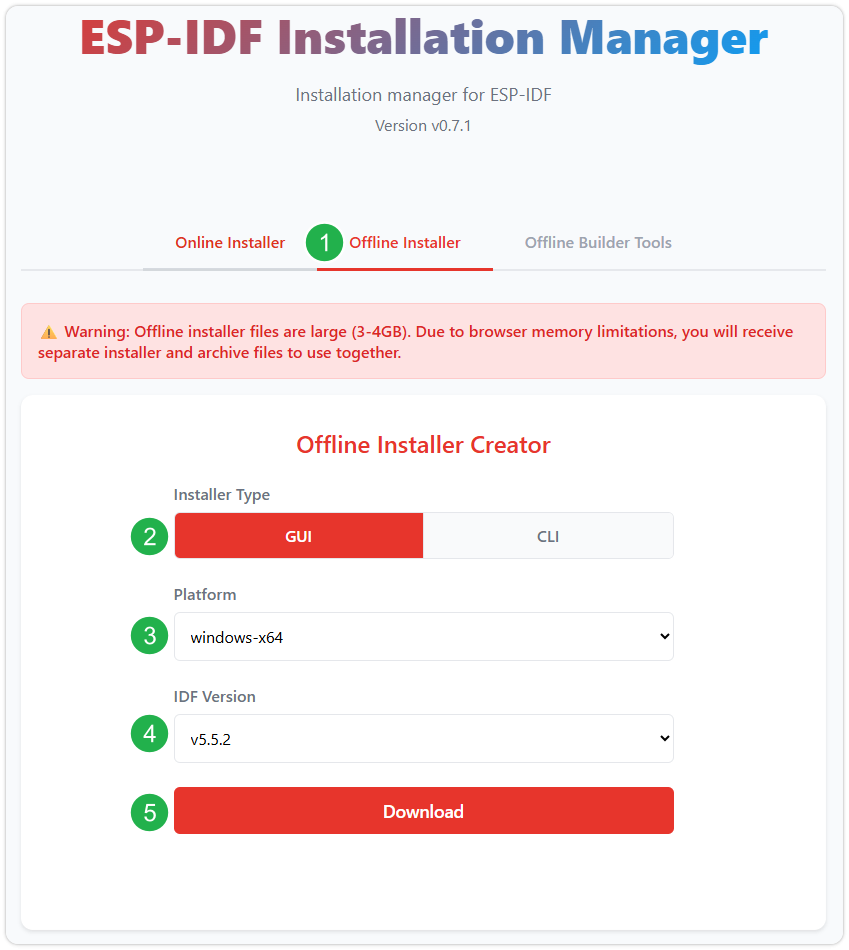
After confirming your selection, click the download button. The browser will automatically download two files: the ESP-IDF Offline Package (.zst) and the ESP-IDF Installer (.exe).
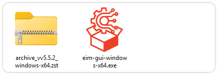
Please wait for both files to finish downloading.
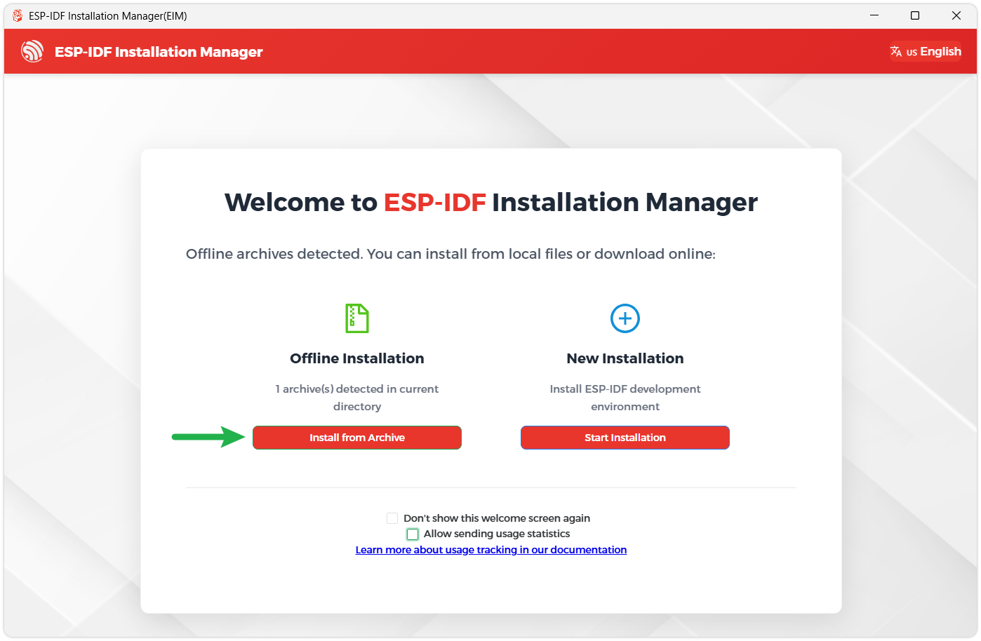
Once the download is complete, double-click to run the ESP-IDF Installer (eim-gui-windows-x64.exe).
The installer will automatically detect if the offline package exists in the same directory. Click Install from archive.
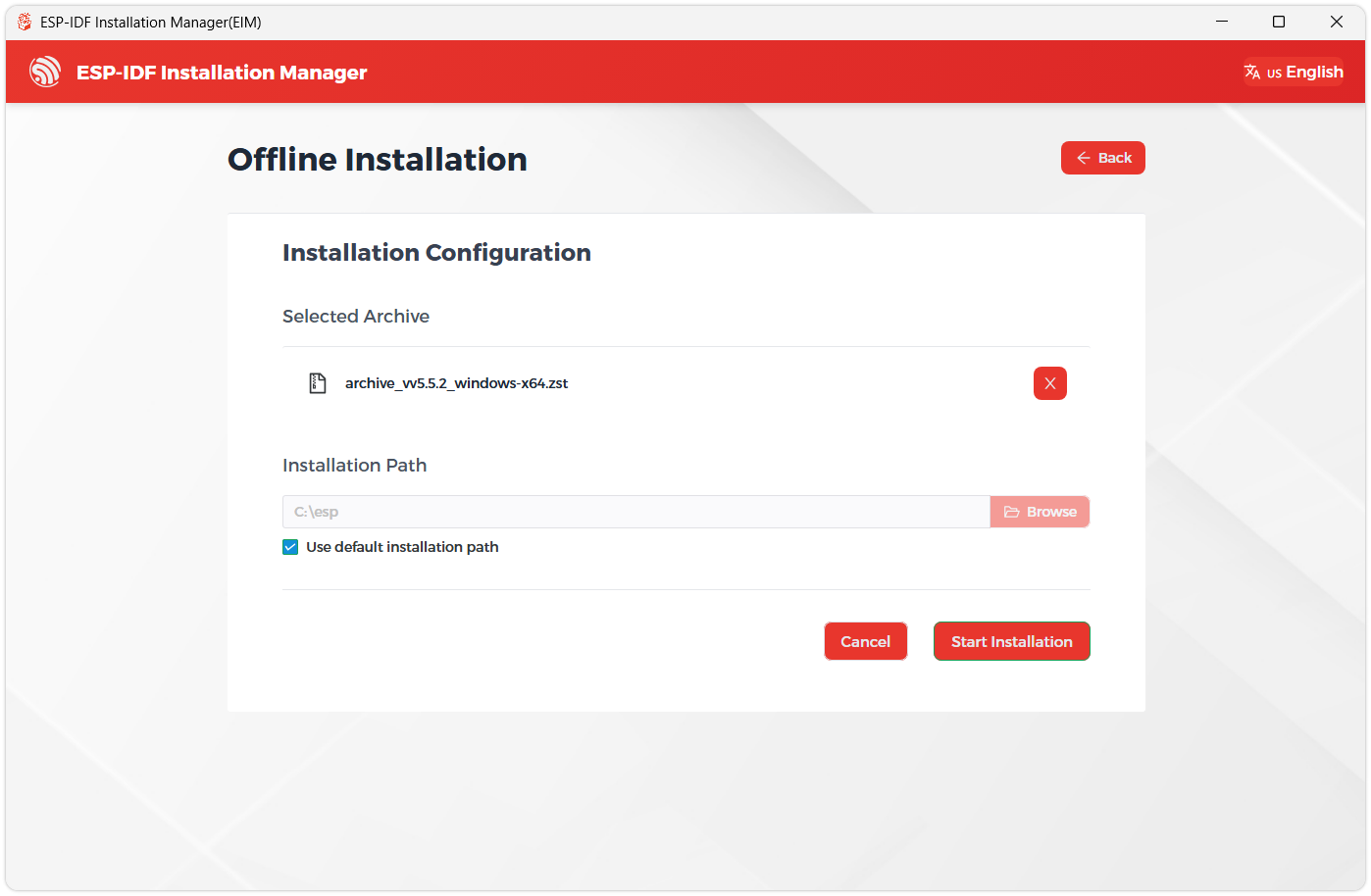
Next, select the installation path. We recommend using the default path. If you need to customize it, ensure the path does not contain Chinese characters or spaces. Click Start installation to proceed.
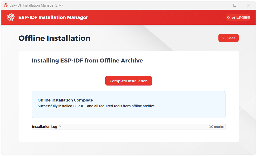
When you see the following screen, the ESP-IDF installation is successful.
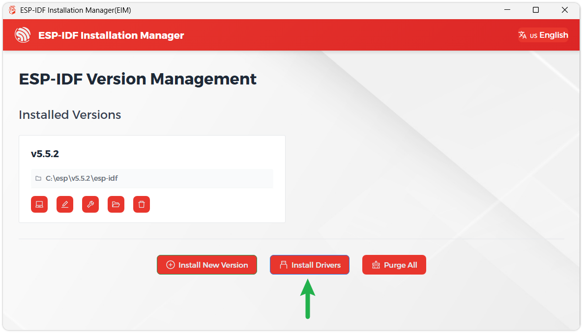
We recommend installing the drivers as well. Click Finish installation, then select Install driver.
Install Visual Studio Code and the ESP-IDF Extension
Download and install Visual Studio Code.
During installation, it is recommended to check Add "Open with Code" action to Windows Explorer file context menu to facilitate opening project folders quickly.
In VS Code, click the Extensions icon
 in the Activity Bar on the side (or use the shortcut Ctrl + Shift + X) to open the Extensions view.
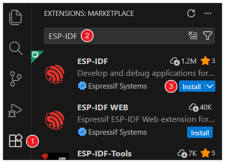
Enter ESP-IDF in the search box, locate the ESP-IDF extension, and click Install.
For ESP-IDF extension versions ≥ 2.0, the extension will automatically detect and recognize the ESP-IDF environment installed in the previous steps, requiring no manual configuration.
Example
The ESP-IDF examples are located in the example/ESP-IDF-V554 directory of the example package. Each example project has been adapted to the onboard hardware resources of the ESP32-C5-Touch-LCD-2.8 and can be used to verify display, touch, audio, TF card, Wi‑Fi, sensors, and GUI functionality.
Building and Flashing
Navigate to any ESP-IDF example directory and run:
cd example/ESP-IDF-V554/02_2048
idf.py build flash monitor
If you need to specify a serial port, replace COMx with the actual port, for example COM5:
idf.py -p COMx build flash monitor
Example List
| Example Directory | Description |
|---|---|
01_ch32_test | CH32V003 I/O expander test, verifies output toggling and input reading |
02_2048 | 2048 game based on LVGL v9, supports touch interaction, score tracking, and game result prompts |
03_sd_lvgl | Mounts a TF card, reads the Test.txt file from the root directory, and displays the content on the LCD |
04_sd_music | Scans MP3 files from the /sdcard/music directory on the TF card and automatically plays the first one |
05_spiff_music | Reads MP3 files from the SPIFFS /music directory and implements a music player with an LVGL interface |
06_wifi_weather | Connects to a specified Wi‑Fi network, retrieves real‑time weather data for Shenzhen, and displays it on the screen |
07_Ball_qmi | Reads QMI8658 accelerometer data and implements a gravity ball that moves with the board's tilt |
08_bookesia | Implements a touch drawing board application using the ESP‑Brookesia framework, with a status bar and memory info |
Usage Notes
- For secondary development, we recommend modifying the application layer or UI logic first. The BSP already provides initialization and low‑level interface definitions for the board's basic hardware resources. Routine UI, interaction, and business logic changes typically do not require BSP modifications. Only modify the BSP if you change hardware connections, adapt low‑level drivers, or add new peripherals.
01_ch32_testtests the onboard CH32V003 I/O expander. CH32V003 is pre‑programmed at the factory and does not require separate CH32 firmware flashing. Running this ESP32-C5 example is sufficient to verify I/O expander communication and control.- The UI for
02_2048is generated with GUI Guider. The layout is mainly incomponents/generated/setup_scr_Game2048.c, event functions are incomponents/generated/events_init.c, and custom initialization and extension logic are incomponents/custom/custom.c. - Before running
03_sd_lvgl, place aTest.txtfile in the root directory of the TF card. - Before running
04_sd_music, create amusicfolder in the root directory of the TF card and place.mp3files inside. 05_spiff_musicuses MP3 files stored in SPIFFS and is suitable for implementing a music player with an LVGL interface.06_wifi_weatherconnects to theweather-wifihotspot by default, password12345678, supporting both 2.4 GHz and 5 GHz bands. To change the hotspot or city, adjust the corresponding configuration in the example source code.- For
07_Ball_qmi, keep the board flat and stationary during calibration to avoid noticeable ball drift. 08_bookesiauses the ESP‑Brookesia framework and serves as a reference for secondary development involving touch GUI, multi‑app interfaces, and drawing board functionality.
01_ch32_test
Example Description
- This example verifies the onboard CH32V003 I/O expander.
- The program initializes the I2C bus and CH32V003 I/O expander, then tests output and input reading functions.
- It first configures
IO_EXP_PIN_0throughIO_EXP_PIN_7as outputs and toggles them high/low cyclically, then switches to input mode and reads the input states.
Hardware Connection
- Connect the board to your computer via USB.
- This example uses only the onboard CH32V003 I/O expander and does not require external modules.
Running Effect
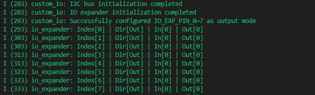
- Serial output shows I2C initialization, I/O expander initialization, output level toggling, and input level reading results.
- If I/O expander communication is normal, you will see successful configuration, output, and reading logs for
IO_EXP_PIN_0~7.
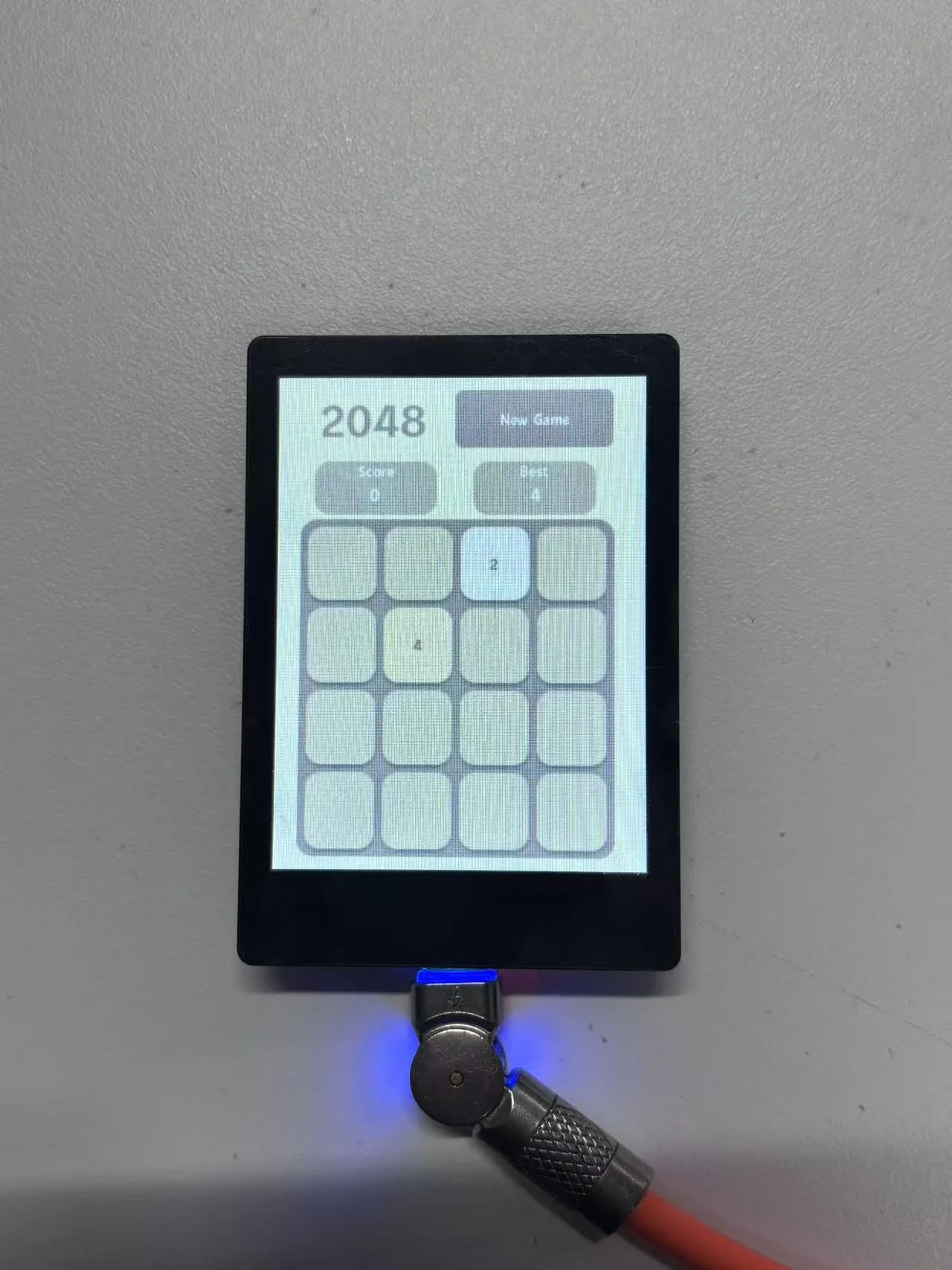
02_2048
Example Description
- This example implements the 2048 game using LVGL v9.
- The UI is generated with GUI Guider. The
main.cin the project callssetup_ui(),custom_init()andevents_init()in sequence to create the UI, perform custom initialization, and bind events. - The screen displays a 4×4 grid, current score, highest score, and a restart button.
- Supports swipe gestures for tile movement; matching numbers are merged and the score is updated accordingly.
- A victory prompt is shown when 2048 is reached, and a game‑over prompt when no moves remain.
- For secondary development, refer to
components/generated/setup_scr_Game2048.cfor the 2048 page layout,components/generated/events_init.cfor touch and button event logic, andcomponents/custom/custom.cfor custom initialization and business extension logic.
Hardware Connection
- Connect the board to your computer via USB.
- This example uses the onboard LCD and capacitive touchscreen and does not require external modules.
Running Effect
- The LCD displays the 2048 game interface.
- Swipe on the touchscreen to control tile movement and see real‑time score updates and game results.
03_sd_lvgl
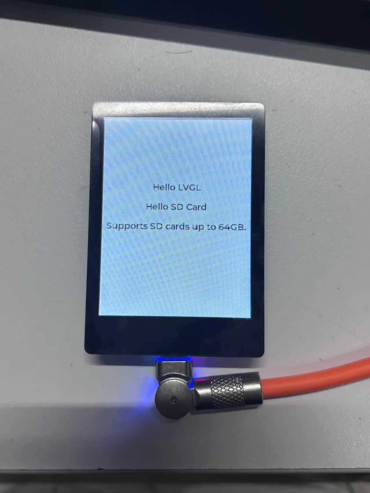
Example Description
- This example demonstrates TF card file reading and LVGL display.
- After startup, the program initializes the LCD and LVGL UI, then mounts the TF card.
- It reads the
Test.txtfile from the root directory of the TF card and displays its content on the LCD. - If the TF card is not detected or file reading fails, the screen shows an appropriate error message.
Hardware Connection
- Connect the board to your computer via USB.
- Insert a FAT32‑formatted TF card into the slot.
- Place a
Test.txtfile in the root directory of the TF card.
Running Effect
- The LCD initially shows
Waiting for SD card.... - After a successful read, the screen displays the text content from
Test.txt. - If no TF card is detected, it shows
SD card not detected!.
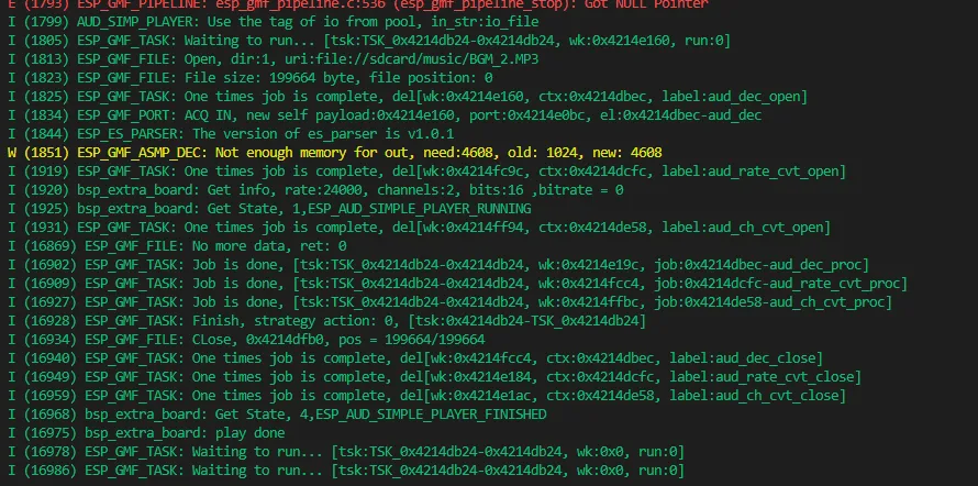
04_sd_music
Example Description
- This example verifies MP3 audio playback from a TF card.
- The program initializes the onboard I/O expander, mounts the TF card, and scans for
.mp3files in the/sdcard/musicdirectory. - After detecting music files, it initializes the audio driver and amplifier, and automatically plays the first MP3.
- This example primarily tests the TF card reading, audio codec, amplifier, and speaker playback chain.
Hardware Connection
- Connect the board to your computer via USB.
- Insert a FAT32‑formatted TF card into the slot.
- Create a
musicfolder in the root directory of the TF card and place.mp3audio files inside. - Connect a speaker to the onboard Speaker interface.
Running Effect
- Serial output shows the list of scanned MP3 files.
- The program automatically plays the first MP3 file found.
- If TF card mounting fails or no MP3 files are found, serial output shows an error message.
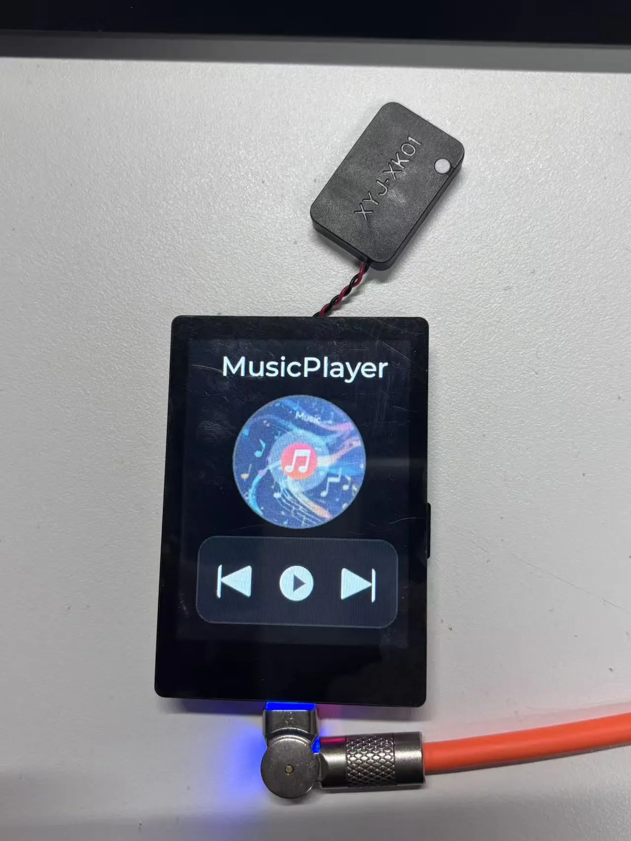
05_spiff_music
Example Description
- This example implements a music player UI using SPIFFS and LVGL v9.
- The program mounts the SPIFFS file system and scans for
.mp3files in the/spiffs/musicdirectory. - The screen displays album art and playback control buttons.
- When the play button is pressed, the program plays the first MP3 and the album art rotates continuously.
- Pressing the button again pauses playback; the rotation stops and resumes from the paused angle when playback continues.
- After playback finishes, the program automatically stops the animation and resets the play button state.
Hardware Connection
- Connect the board to your computer via USB.
- Connect a speaker to the onboard Speaker interface.
- The MP3 files must be pre‑packaged into the SPIFFS
musicdirectory.
Running Effect
- The LCD displays the music player interface.
- Click the play button to start playback and see the rotating album art animation.
- Supports play, pause, and playback‑end state recovery.
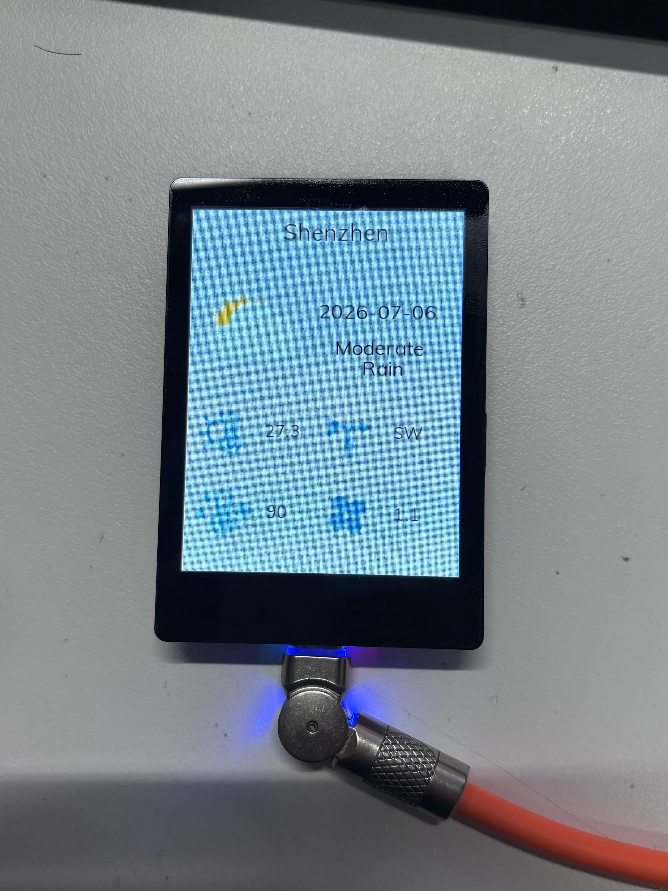
06_wifi_weather
Example Description
- This example demonstrates Wi‑Fi connectivity and weather data display.
- The program connects to a fixed Wi‑Fi hotspot and retrieves real‑time weather data for Shenzhen via HTTP request.
- The screen displays city, date, weather status, temperature, humidity, wind speed, and wind direction.
- Supports automatic Wi‑Fi reconnection on disconnection.
- Weather data refreshes periodically, approximately every 5 minutes after a successful fetch.
Default Wi‑Fi Configuration
| Item | Default Value |
|---|---|
| Wi-Fi SSID | weather-wifi |
| Wi-Fi Password | 12345678 |
| Wi-Fi Band | 2.4 GHz or 5 GHz |
| Weather City | Shenzhen |
| Request Server | cn.apihz.cn |
Hardware Connection
- Before powering on, turn on a Wi‑Fi hotspot that matches the example configuration.
- Connect the board to your computer via USB and power it on.
- The hotspot can use either 2.4 GHz or 5 GHz band, but the SSID and password must match the example, and the hotspot must have internet access.
- This example uses the onboard LCD and Wi‑Fi, and does not require external modules.
Running Effect
- After connecting to Wi‑Fi, the screen displays Shenzhen weather information.
- If the hotspot is not available or network access fails, the program will keep retrying connection and requests.
07_Ball_qmi
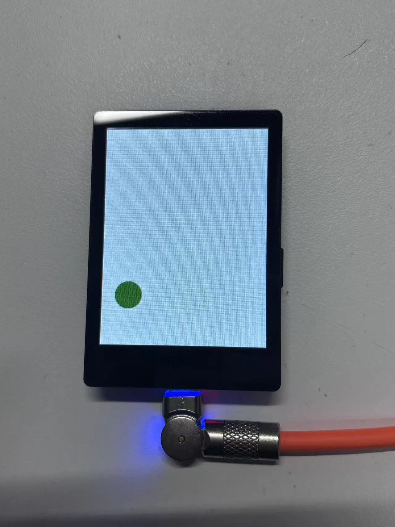
Example Description
- This example demonstrates QMI8658 accelerometer interaction with LVGL.
- The program initializes QMI8658 with 8G range and 500 Hz output data rate.
- After startup, it performs a level calibration to eliminate offset in the stationary state.
- After calibration, a ball appears at the center of the screen and moves in real time according to the board's tilt direction.
- The ball's movement is constrained to stay within the screen boundaries and rounded corner area.
Hardware Connection
- Connect the board to your computer via USB.
- This example uses the onboard LCD and QMI8658 six‑axis sensor and does not require external modules.
- Place the board flat on a stable desk during calibration.
Running Effect
- The screen shows a green ball.
- When you tilt the board, the ball moves in the direction of gravity.
- Serial output shows calibration status and sensor‑related logs.
08_bookesia
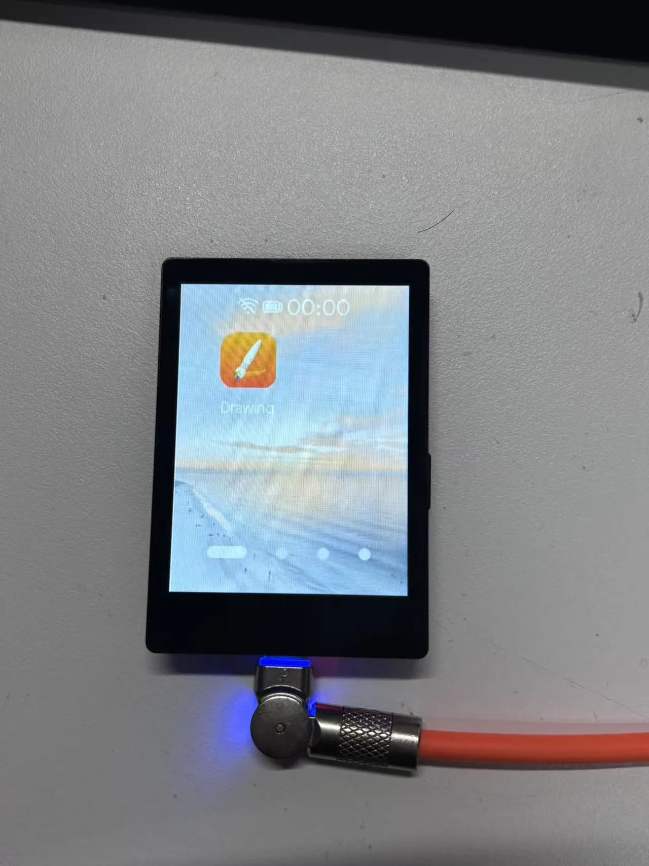
Example Description
- This example implements a phone‑style GUI using the ESP‑Brookesia framework.
- It uses a 240×320 dark theme with a status bar, app manager, and touch interaction.
- The example installs system default apps and additionally installs a Drawing Board app.
- The Drawing Board app supports freehand drawing on the capacitive touchscreen.
- The status bar clock refreshes every second.
- The recent tasks view periodically displays SRAM and PSRAM usage.
Hardware Connection
- Connect the board to your computer via USB.
- This example uses the onboard LCD and capacitive touchscreen and does not require external modules.
Running Effect
- The LCD displays the ESP‑Brookesia style interface.
- You can enter the Drawing Board app via touch and start drawing.
- The system interface supports status bar, recent tasks, and memory information display.
Resources
1. Hardware Resources
Development Board Design Files
2. Technical Manuals
ESP32-C5 Chip Official Manuals
Onboard Component Datasheets
3. Example
4. Software Tools
- Arduino:
- VS Code:
- Debugging Tools:
- Firmware Flashing Tool:
- Other Resource Links:
Support
Monday-Friday (9:30-6:30) Saturday (9:30-5:30)
Email: services01@spotpear.com
[Tutorial Navigation]
- Features
- Onboard Resources
- Interface Introduction
- Dimensions
- Factory Firmware Instructions
- Required Components
- Wi-Fi Configuration
- Precautions
- BAT_PWR Button Test
- Firmware Download
- Example Overview
- App Example Introduction
- Working with Arduino
- Arduino Getting Started
- Setting Up the Development Environment
- 1. Installing and Configuring the Arduino IDE
- 2. Installing the ESP32 Board Support Package
- 3. Installing Libraries and Example Dependencies
- 4. Arduino Project Parameter Settings
- Example
- XiaoZhi AI Application Tutorial
- 0. Firmware Flashing Process Reference
- 1. Flashing Without a Development Environment
- 2. Flashing with ESP-IDF Environment
- 2.1 Download the Project from XiaoZhi GitHub
- 2.2 Environment Setup
- 2.3 Configuration and Compilation
- 2.4 Start Network Provisioning
- 2.5 Add a New Device to the Management Console
- 3. XiaoZhi Resources
- Working with ESP-IDF
- ESP-IDF Getting Started
- Setting Up the Development Environment
- Example
- Resources
- Support