




- sales/support
Google Chat:---
- sales
+86-0755-88291180
- sales01
sales@spotpear.com
- sales02
dragon_manager@163.com
- support
tech-support@spotpear.com
- CEO-Complaints
zhoujie@spotpear.com
- Only Tech-Support
WhatsApp:13246739196
- Purchase/Shipping/Refund
WhatsApp:13424403025
- HOME
- >
- ARTICLES
- >
- Common Moudle
- >
- ESP
ESP32-C6-LCD-0.85 User Guide
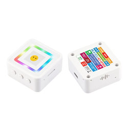
Features
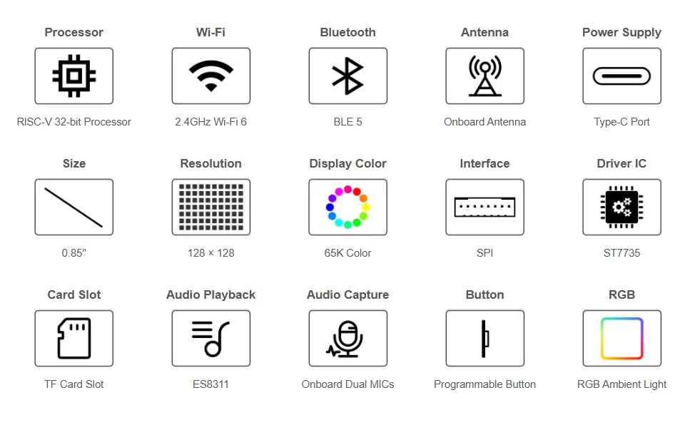
- Powered by the ESP32-C6 high-performance 32-bit RISC-V processor, with a main frequency of up to 160MHz
- Integrated WiFi 6, Bluetooth 5 and IEEE 802.15.4 (Zigbee 3.0 and Thread) wireless communication, with superior RF performance
- Built‑in 512KB SRAM, 320KB ROM, and 8MB Flash
- Features a Type-C interface, enhancing user convenience and device compatibility
- Onboard 0.85inch LCD screen, 128 × 128 resolution, 65K colors
- Onboard 8 ring‑shaped RGB LEDs, programmable to achieve various dynamic lighting effects
- Onboard 3.7V MX1.25 lithium battery charge/discharge interface
- Exposed I2C and UART pads for connecting external devices and debugging, allowing flexible peripheral configuration
- Onboard TF card slot, providing expanded storage, fast data transfer, and flexibility, suitable for data logging and media playback, simplifying circuit design
- Onboard ES8311 audio codec chip, dual‑MIC microphone module, and other resources
Onboard Resources
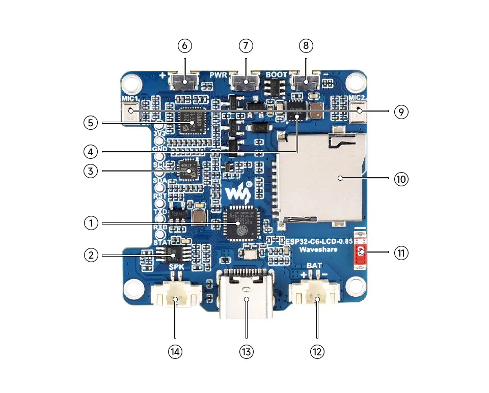
- ESP32-C6FH8 Integrates a RISC-V single-core processor running at 160MHz, supports 2.4GHz Wi-Fi 6 and BLE 5
- NS4150 Audio power amplifier chip
- ES8311 Audio codec chip
- Battery charge/discharge management chip
- ES7210 ADC chip for echo cancellation circuit
- PLUS button Supports user‑defined functions
- PWR Power Button Controls power on/off and supports custom functions
- BOOT Button Used for device startup and functional debugging
- Microphone
- TF Card Slot
- Onboard Antenna Supports 2.4GHz Wi-Fi (802.11 b/g/n) and Bluetooth 5 (LE)
- Battery Header MX1.25 2PIN connector for 3.7V lithium battery, supports charging and discharging
- USB Type-C Interface ESP32-C6 USB interface for program flashing and log printing
- Speaker header
LCD and Its Controller
- The built-in controller used for this LCD is the ST7735, an LCD controller with 128 x RGB x 160 pixels, while the LCD itself has a resolution of 128(H)RGB x 128(V). Since the initialization can be set to both landscape and portrait modes, the internal RAM of the LCD is not fully utilized
- This LCD supports 8-bit, 9-bit, and 16-bit input color formats, namely RGB444 and RGB565. This example uses the RGB565 color format, which is a common RGB format
- The LCD uses a 4-wire SPI communication interface, which significantly saves GPIO pins while maintaining relatively fast communication speeds
SPI Communication Protocol:
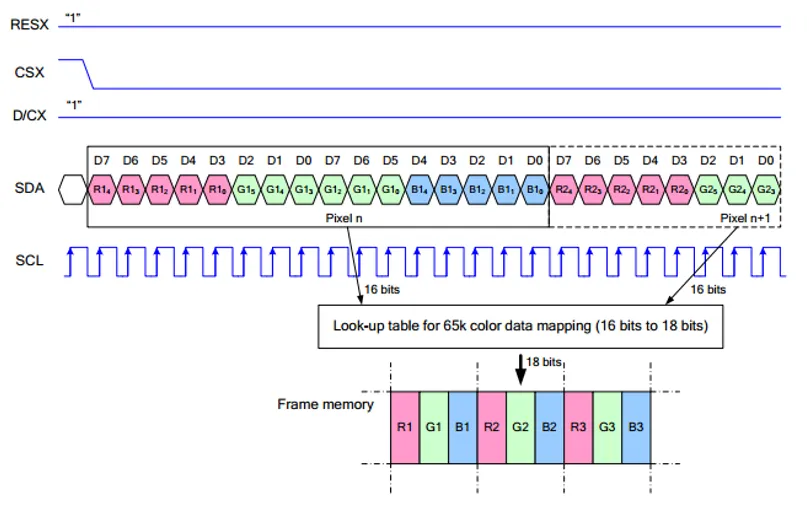
Note: Unlike the traditional SPI protocol, because only display functionality is needed, the data line from the slave to the master is omitted
RESX is the Reset pin; it is pulled low during module power-up and is normally set to 1.
CSX is the slave chip select pin; the chip is enabled only when CS is low
D/CX is the data/command control pin of the chip. When DC = 0, commands are written; when DC = 1, data is written.
SDA is the data transmission pin, specifically for RGB data.
SCL is the SPI communication clock pin.
For SPI communication, data transmission follows a specific timing sequence, which are determined by the combination of clock phase (CPHA) and clock polarity (CPOL):
The level of CPHA determines whether data is captured on the first or second clock transition edge of the serial synchronous clock. When CPHA = 0, data is captured on the first transition edge;
The level of CPOL determines the idle level of the serial synchronous clock. CPOL = 0 means the idle state is low level.
As shown in the diagram, data transmission begins on the first falling edge of SCLK, with 8 bits of data transferred per clock cycle using SPI mode 0, transmitting bits from MSB to LSB
Pinout Definition
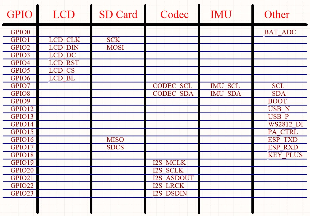
When using the reserved GPIO pads on the ESP32-C6-LCD-0.85 board, pay attention to the wiring and corresponding functions to avoid damaging the development board due to incorrect connections.
Dimensions
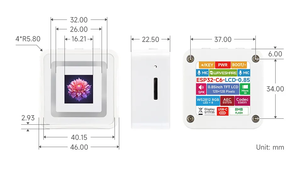
User Guide
To help users quickly understand the various functions of the product, we provide a series of test examples to familiarize customers with the use of each interface. Besides the ESP32-C6-LCD-0.85 host and its accompanying components, the following items are required to run the examples:
Required Components
- ESP32-C6-LCD-0.85 ×1
- TF card ×1 (not required, needed only for TF card examples)
Assembly Guide
When installing the battery, assemble the PC insulating sheet. It provides insulation and flame retardancy to isolate the battery from the PCB board.
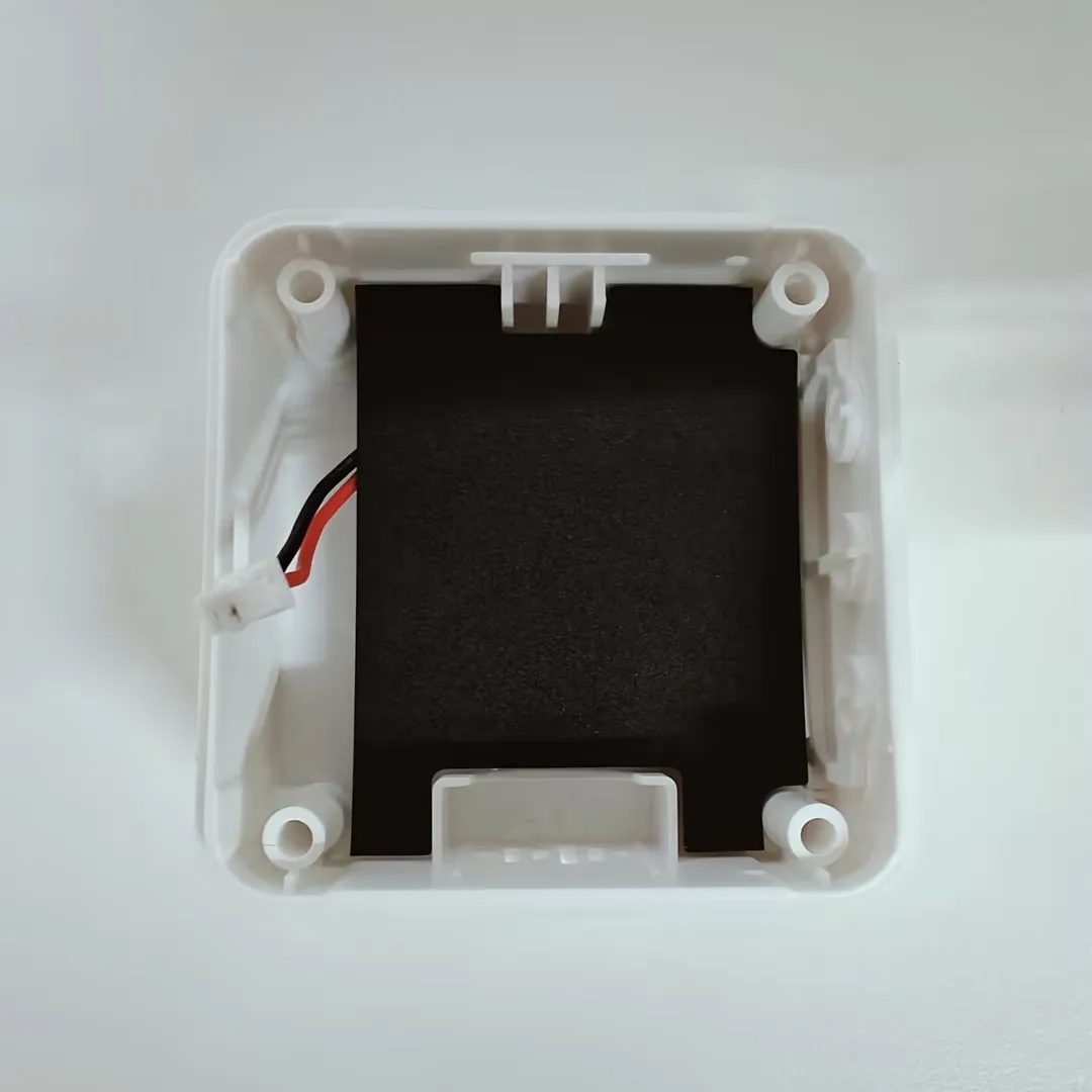
Precautions
⚠️ USB Download Precautions (Important)
If the port is not recognized, please enter Boot mode:
- Press and hold the BOOT button
- Connect the USB cable to the computer
- Release the BOOT button
After the download is complete, power cycle the board to run the program.
Firmware Download
- The example programs are located in the
Firmwaredirectory of the example package
Firmware Flashing
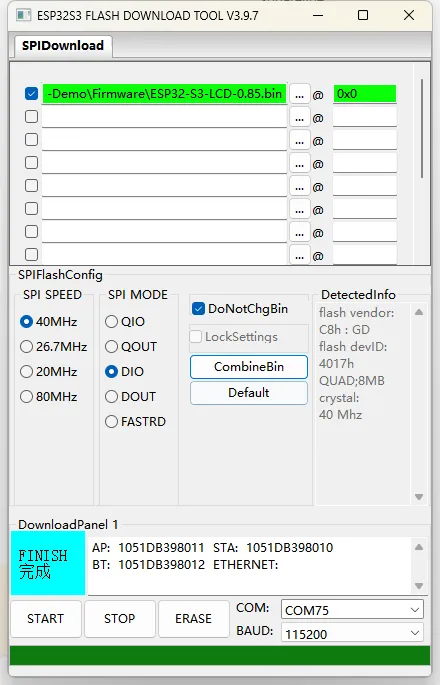
- Unzip the software resource package (Flash_download_tool)
- Open the flash_download_tool_3.9.7.exe software. Select
ESP32-S3andUSBbased on the development board's MCU and interface.ESP32-C6andUSB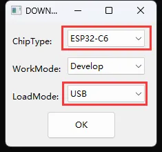
- Parameter Settings
- ①. Select the COM port corresponding to the development board
- ②. Select the highest baud rate, 1152000
- ③. Click "..." to select the bin file from the
ESP32-C6-LCD-0.85-Demo\Firmwaredirectory provided in the example package. Manually enter the download address "0x00", and check the box on the far left - ④. Start flashing
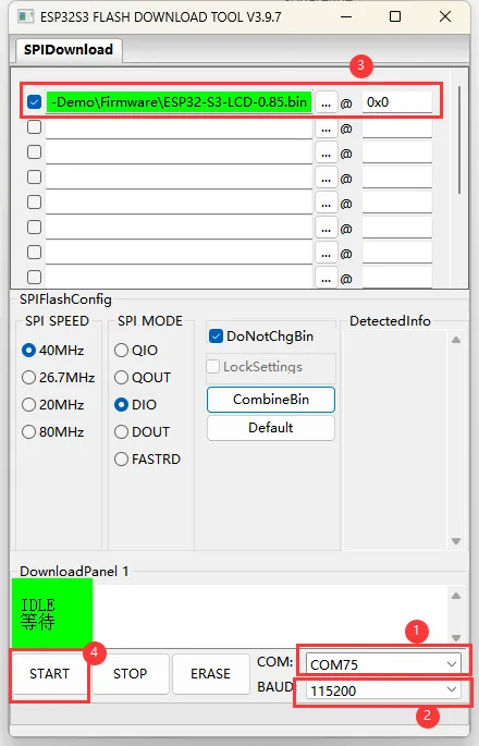
- Flashing complete (the flashing process takes some time, please be patient)
- Press the reset button and observe the result
XiaoZhi AI Application Tutorial
XiaozhiAI (XiaoZhi AI) is an open-source AI voice chatbot project based on the ESP32 development board, aiming to bring the general intelligence of large language models (LLMs) to edge devices. It provides a software-hardware integrated solution supporting full-duplex voice conversations and IoT device control, dedicated to assisting developers in building highly customized physical AI agents quickly and at low cost.
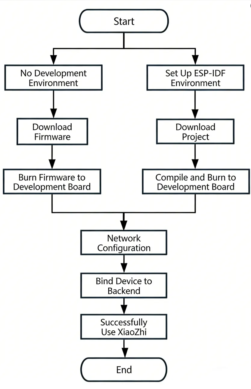
This article demonstrates how to flash firmware for Waveshare ESP32 development boards that support XiaoZhi AI, covering two methods: flashing without a development environment (directly flashing precompiled firmware) and flashing with a development environment (compiling from source and flashing).
0. Firmware Flashing Process Reference
This section uses the ESP32-S3-Touch-AMOLED-1.8 development board as an example. The steps are similar for other development boards.
Please first confirm that your hardware is listed in the XiaoZhi AI Supported Products List.
1. Flashing Without a Development Environment
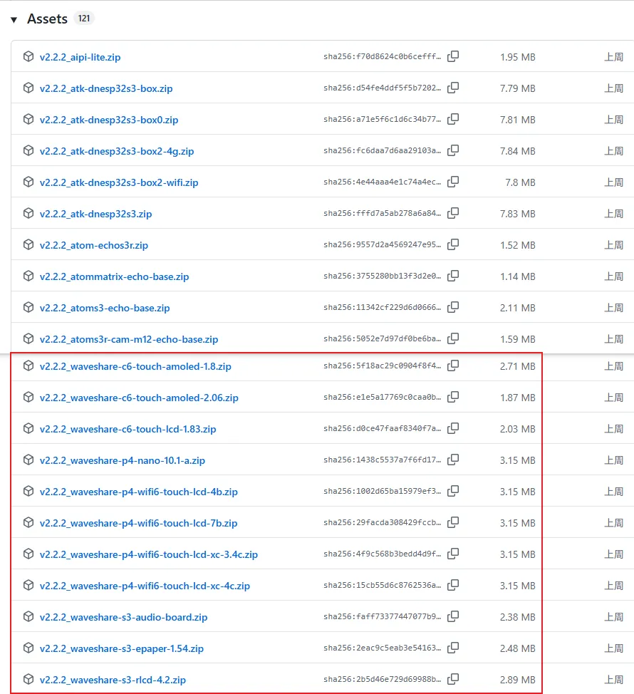
1.1 Download Firmware from XiaoZhi Official GitHub
Visit the XiaoZhi GitHub to download the firmware file for your device. Click Assets to expand the full file list:
Refer to the Flash Firmware Flashing and Erasing Tutorial to complete the firmware flashing.
1.2 Download Firmware from Waveshare GitHub
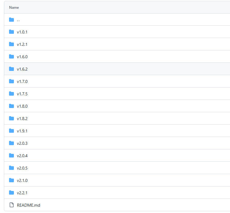
This repository aggregates firmware for Waveshare ESP32 development boards that support XiaoZhi AI. All firmware has been tested and verified on the corresponding boards, making it convenient for users to find and download. Firmware versions may be updated slightly later than the official XiaoZhi repository.
Visit the Waveshare GitHub repository and download the appropriate firmware version for your needs:
Refer to the Flash Firmware Flashing and Erasing Tutorial to complete the firmware flashing.
2. Flashing with ESP-IDF Environment
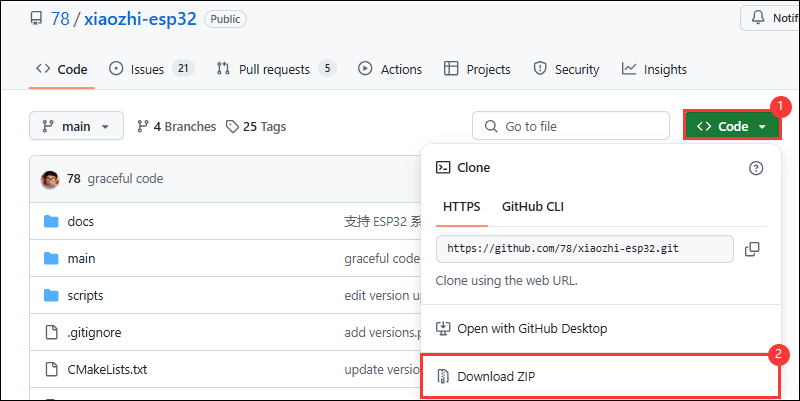
2.1 Download the Project from XiaoZhi GitHub
Visit the XiaoZhi AI Chatbot repository to download the complete project code:
2.2 Environment Setup
Refer to the ESP-IDF Environment Setup Tutorial to configure the development environment.
2.3 Configuration and Compilation
Click
 to select the target device. Choose the chip model corresponding to your development board (e.g.,
 esp32s3):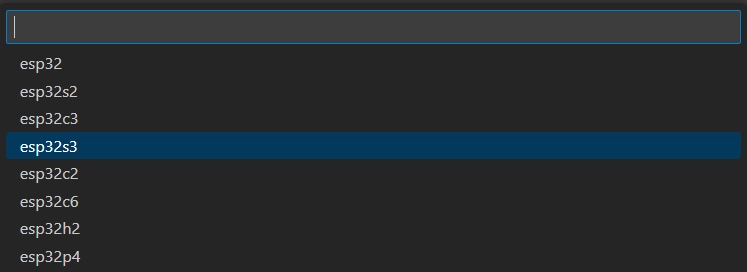 TIP
TIPWhen setting the target device, ESP-IDF will automatically configure the corresponding toolchain and libraries. This process may take some time, please be patient. For more details, please refer to the Official Documentation.
Click
 to open the ESP-IDF terminal, then execute the command
 idf.py menuconfigto enter the configuration interface. Select Xiaozhi Assistant: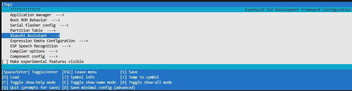
Select Board Type to choose the development board type:
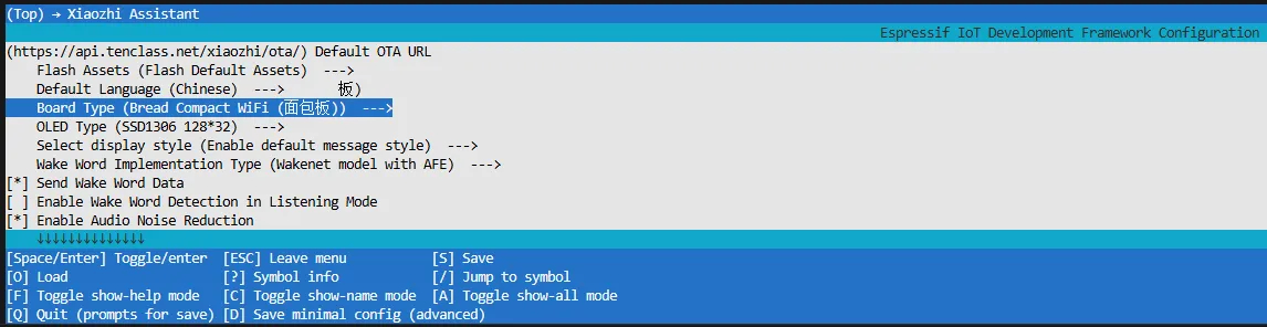
Choose the product model corresponding to your development board:
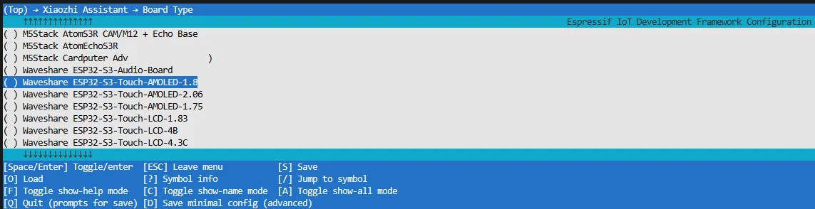
Press the S key to save the configuration and exit. Then click the
 to automatically complete compilation, flashing, and serial monitoring.
2.4 Start Network Provisioning
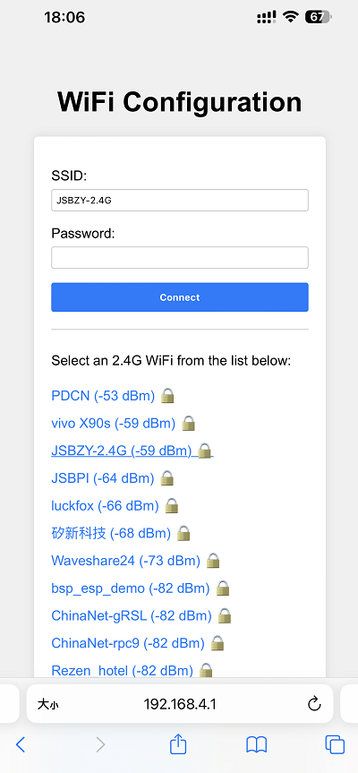
Connect your phone or computer to the device's Wi-Fi hotspot: Xiaozhi-xxxxxx. After successful connection, the configuration page should automatically pop up. If not, manually open a browser and visit
http://192.168.4.1.On the network configuration page, select the Wi-Fi name you want to connect to (only 2.4G band is supported; to connect to an iPhone hotspot, enable Max Compatibility in your phone's system settings). The SSID will be auto-filled. Enter the password and click Connect to start connecting:
2.5 Add a New Device to the Management Console
Ensure the device has successfully connected to the Internet. The device will then broadcast a 6-digit device verification code (you can wake the device again to replay the code).
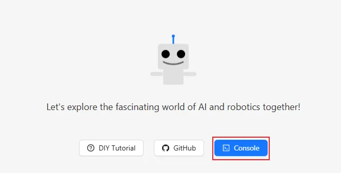
Visit the XiaoZhi AI Console. If you haven't registered, complete the registration and log in:
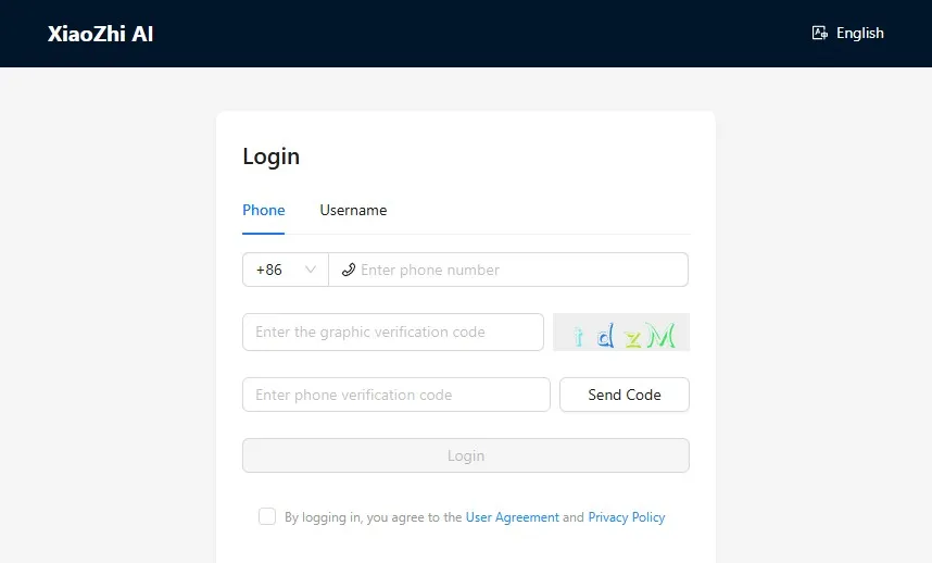
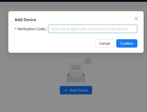
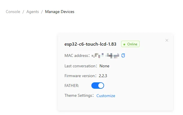
Enter the 6-digit verification code. The device will automatically activate and appear on the Device Management page, ready for normal use.
Say the wake word "Hello XiaoZhi" to wake the device and start voice conversations.
ESP32-S3-Touch-AMOLED-1.8 Button Instructions:
- BOOT button: Press to wake XiaoZhi
- PWR button: Short press to power on; long press for more than 6 seconds to power off
3. XiaoZhi Resources
Working with Arduino
This chapter contains the following sections. Please read as needed:
Arduino Getting Started
New to Arduino ESP32 development and looking for a quick start? We have prepared a comprehensive Getting Started Tutorial for you.
- Section 0: Getting to Know ESP32
- Section 1: Installing and Configuring Arduino IDE
- Section 2: Arduino Basics
- Section 3: Digital Output/Input
- Section 4: Analog Input
- Section 5: Pulse Width Modulation (PWM)
- Section 6: Serial Communication (UART)
- Section 7: I2C Communication
- Section 8: SPI Communication
- Section 9: Wi-Fi Basics
- Section 10: Web Server
- Section 11: Bluetooth
- Section 12: LVGL GUI Development
- Section 13: Comprehensive Project
Note: This tutorial uses the ESP32-S3-Zero as a reference example, and all hardware code is based on its pinout. Before you start, we recommend checking the pinout of your development board to ensure the pin configuration is correct.
Setting Up Development Environment
1. Installing and Configuring Arduino IDE
Please refer to the tutorial Installing and Configuring Arduino IDE to download and install the Arduino IDE and add ESP32 support.
2. Installing Libraries
To run the example, you need to install the corresponding library. The example program package for the ESP32-C6-LCD-0.85 development board can be downloaded from here. The Arduino\libraries directory within this package contains all the necessary library files required for this tutorial.
| Library or File Name | Description | Version | Installation Method |
|---|---|---|---|
| lvgl | LVGL graphics library | v8.4.0 or v9.3.0 | Via Library Manager or manual install |
| GFX_Library_for_Arduino | GFX graphics library | v1.6.0 | Via Library Manager or manual install |
| U8g2 | Graphics display library | v2.35.30 | Via Library Manager or manual install |
| FastLED | RGB LED driver library | v3.10.1 | Via Library Manager or manual install |
| ESP32-audioI2S-master | Audio processing library | v3.4.0 | Via Library Manager or manual install |
| OneButton | Button library | v2.6.1 | Via Library Manager or manual install |
There are strong dependencies between versions of LVGL and its driver libraries. For example, a driver written for LVGL v8 may not be compatible with LVGL v9. To ensure that the examples can be reproduced reliably, it is recommended to use the specific versions listed in the table above. Mixing different versions of libraries may lead to compilation failures or runtime errors.
Installation Steps:
Extract the downloaded example package.
Copy all folders (ESP32-audioI2S-master, GFX_Library_for_Arduino, etc.) from its
Arduino\librariesdirectory to the Arduino libraries folder.INFOThe path to the Arduino libraries folder is typically:
c:\Users\<username>\Documents\Arduino\libraries.You can also locate it in the Arduino IDE by going to File > Preferences and checking the "Sketchbook location". The libraries folder is the
librariessubfolder within this path.For other installation methods, please refer to: Arduino Library Management Tutorial.
Required Board Installation Instructions for ESP32-C6-LCD-0.85
| Board Name | Installation Requirement | Version Requirement |
|---|---|---|
| ESP32 by Espressif Systems | "Install Offline" / "Install Online" | 3.2.0 |
3. Other Tips
For the ESP32-C6-LCD-0.85, you need to select and configure the board.

- Select the ESP32C6 Dev Module for ESP32-C6-LCD-0.85.
- Select the USB port.
- The ESP32-C6-LCD-0.85 uses the ESP32-C6 native USB interface, not a UART-to-USB bridge. For serial communication:
The
printf()function can be used directly;To use the
Serial.println()function, additional configuration is required: Enable the "USB CDC On Boot" option in the IDE's Tools menu, or declare anHWCDCobject in your code to handle USB serial communication.
- Select 8MB Flash
- Select a Partition Table of the appropriate size
Example
The Arduino examples are located in the Arduino/examples directory of the example package.
| Example | Basic Description | Dependency Library |
|---|---|---|
| 01_audio_out | Read audio files from TF card and play them | ESP32-audioI2S-master |
| 02_button_example | Button test | OneButton |
| 03_ws2812b_example | Test RGB LED | FastLED |
| 04_gfx_helloworld | Display HelloWorld on the screen | GFX_Library_for_Arduino |
| 05_esp_wifi_analyzer | Display WiFi signal strength on the screen | GFX_Library_for_Arduino |
| 06_gfx_u8g2_font | Display text in multiple languages by loading fonts | GFX_Library_for_Arduino, U8g2 |
| 07_sd_card_test | Test TF card read/write | --- |
| 08_lvgl_example_v8 | lvgl v8.4.0 example | GFX_Library_for_Arduino, lvgl |
| 09_lvgl_example_v9 | lvgl v9.3.0 example | GFX_Library_for_Arduino, lvgl |
01_audio_out
This example demonstrates the ESP32-C6-LCD-0.85 playing audio through a speaker; the screen shows no output.
Code Analysis
- Set I2S pins:void setupI2S() {i2s.setPins(I2S_BCK_PIN, I2S_LRCK_PIN, I2S_DOUT_PIN, I2S_DIN_PIN, I2S_MCK_PIN);// Initialize the I2S bus in standard modeif (!i2s.begin(I2S_MODE_STD, EXAMPLE_SAMPLE_RATE, I2S_DATA_BIT_WIDTH_16BIT, I2S_SLOT_MODE_MONO, I2S_STD_SLOT_LEFT)) {Serial.println("Failed to initialize I2S bus!");return;}}
- Set the audio data to be played:i2s.write((uint8_t *)audio_data, AUDIO_SAMPLES * 2);
Operation Result
- The device will play auido directly without showing content on the screen
02_button_example
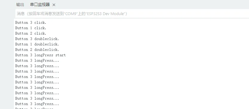
This example demonstrates how to use the OneButton library to read button states such as single click, double click, and long press, and print them via the serial monitor.
Code Analysis
Bind callback functions:
button1.attachClick(click1);button1.attachDoubleClick(doubleclick1);button1.attachLongPressStart(longPressStart1);button1.attachLongPressStop(longPressStop1);button1.attachDuringLongPress(longPress1);
Operation Result
- The screen shows no output
- Button information is printed to the serial monitor
03_ws2812b_example
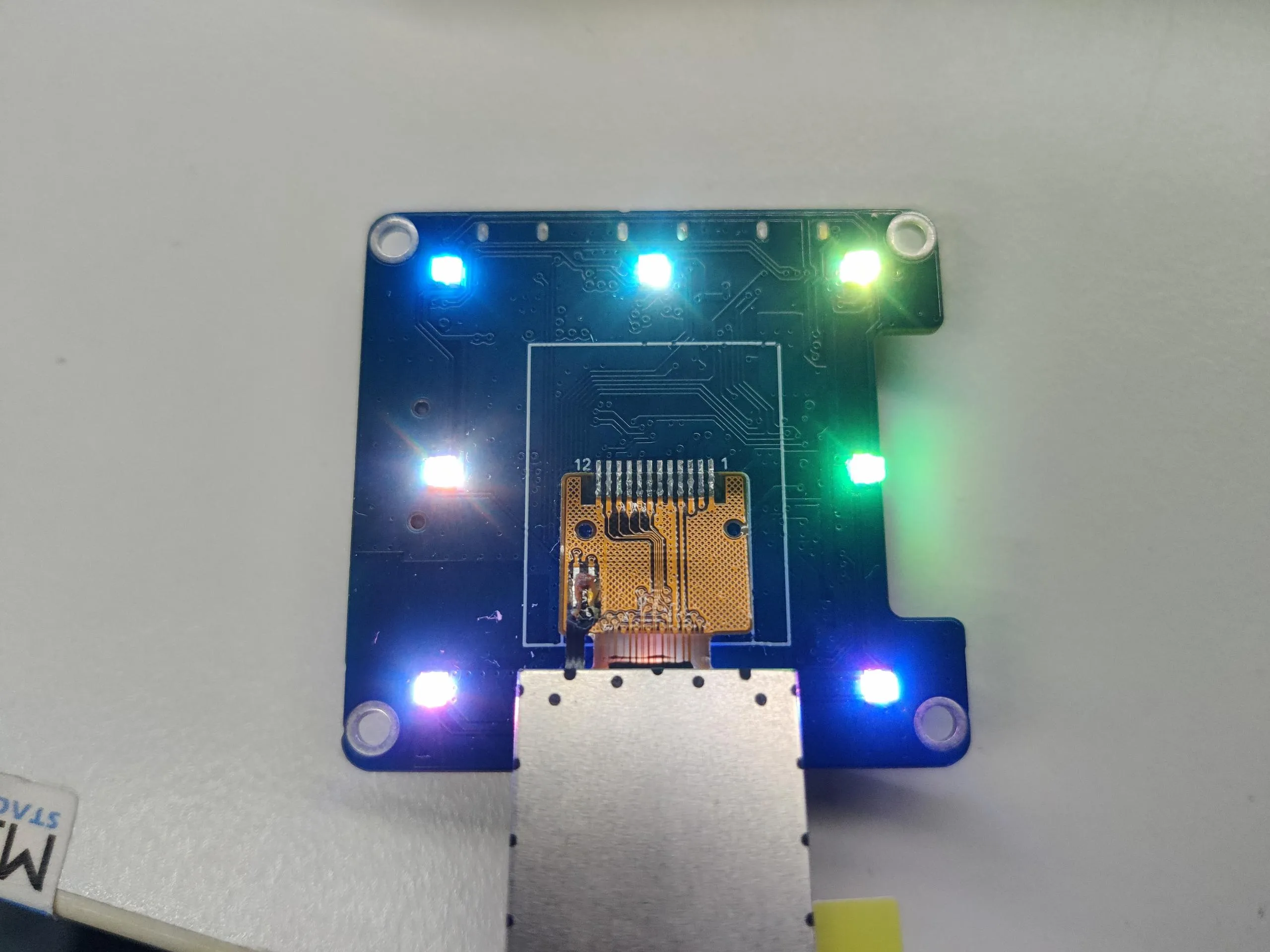
This example uses the FastLED library to drive the ws2812b RGB LED on the ESP32-C6-LCD-0.85, changing to a random color every 500ms.
Code Analysis
Initialize ws2812b and set brightness:
FastLED.addLeds<WS2812B, DATA_PIN, RGB>(leds, NUM_LEDS); // GRB ordering is typicalFastLED.setBrightness(100); // 0-255
Operation Result
- The screen shows no output
- The RGB LED changes to a random color every 500ms
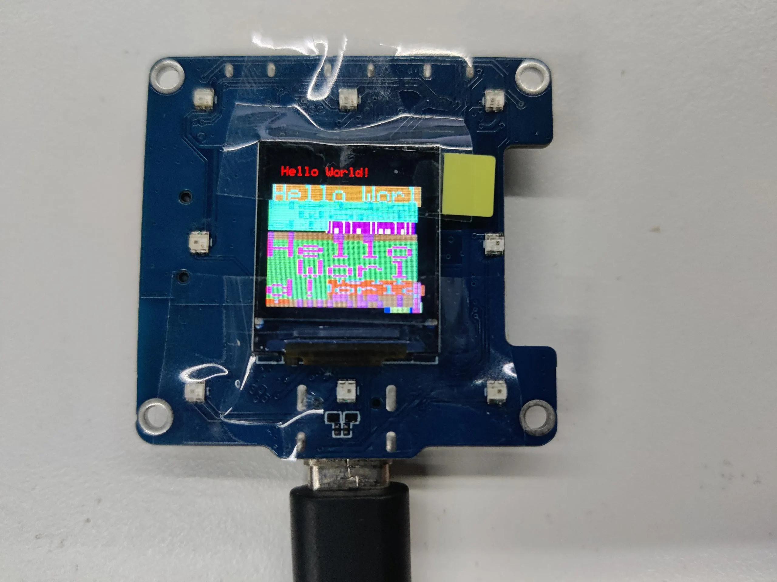
04_gfx_helloworld
This example demonstrates the ESP32-C6-LCD-0.85 using the GFX_Library_for_Arduino library to drive the screen and display "HelloWorld" on the screen.
Code Analysis
- Configure the screen interface and screen resolution, etc.Arduino_DataBus *bus = new Arduino_HWSPI(3 /* DC */, 5 /* CS */, 1 /* SCK */, 2/* MOSI */, GFX_NOT_DEFINED /* MISO */);Arduino_GFX *gfx = new Arduino_ST7735(bus, 4 /* RST */, 0 /* rotation */, true /* IPS */,128 /* width */, 128 /* height */,2 /* col offset 1 */, 3 /* row offset 1 */);
Operation Result
- The screen displays as follows:
05_esp_wifi_analyzer
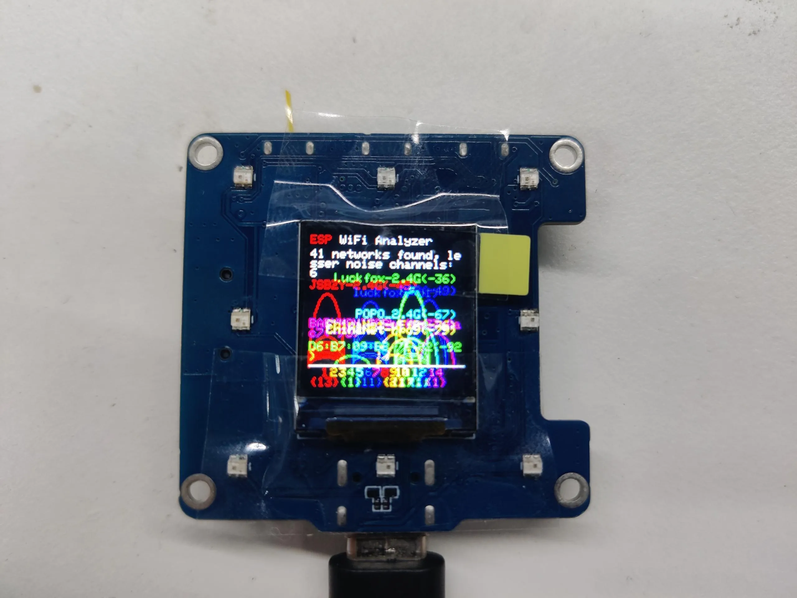
This example demonstrates the ESP32-C6-LCD-0.85 using a GFX_Library_for_Arduino library to display the signal strength of the WiFi band
Operation Result
- The screen displays as follows:
06_gfx_u8g2_font
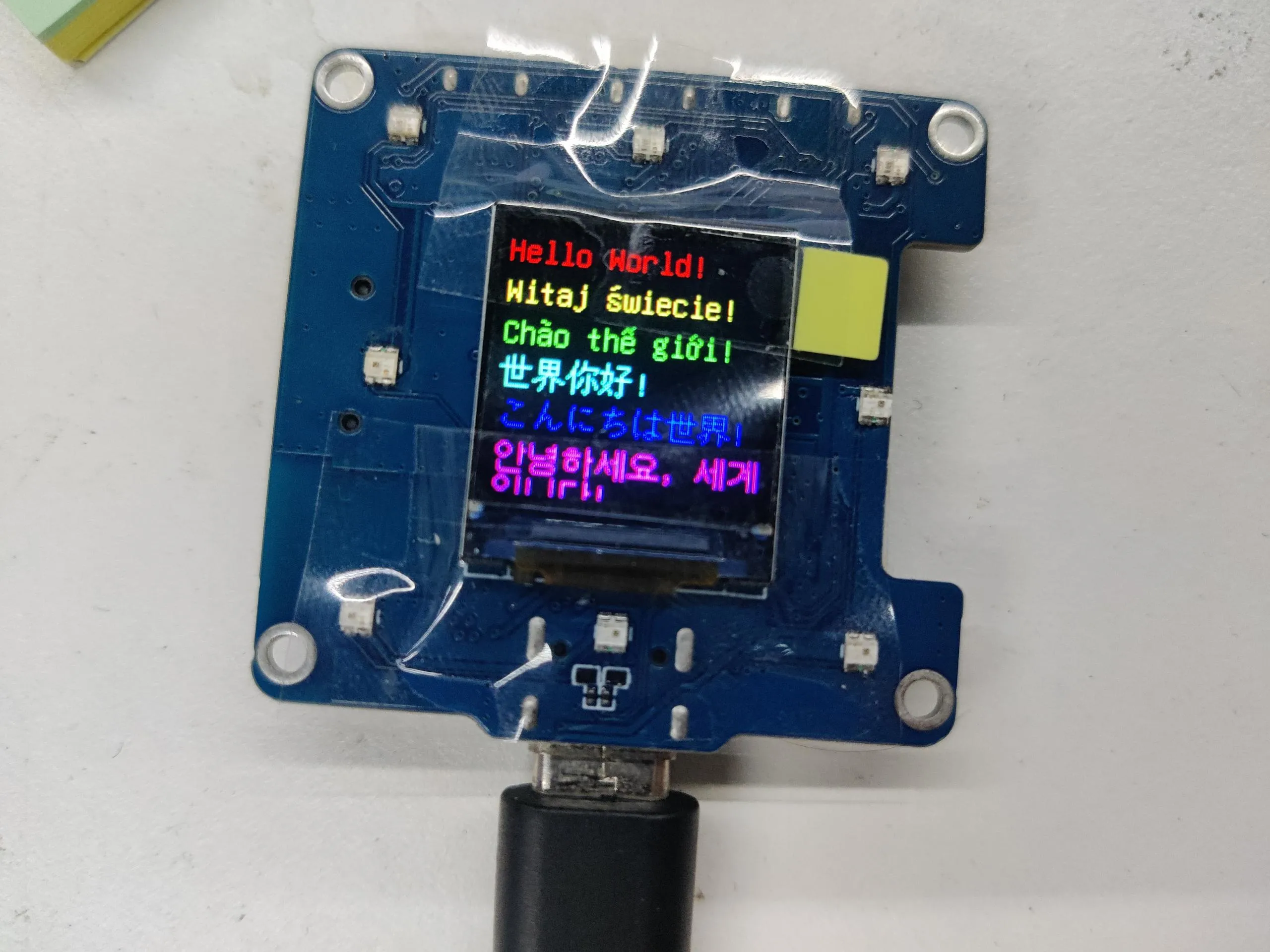
This example demonstrates how ESP32-C6-LCD-0.85 uses GFX_Library_for_Arduino libraries to load font libraries to display them in various languages
Operation Result
- The screen displays as follows:
07_sd_card_test
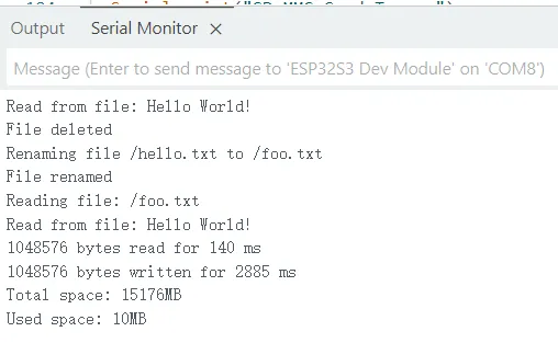
This example tests the TF card read/write functionality on the ESP32-C6-LCD-0.85.
Code
07_sd_card_test.ino
Code Analysis
TF card initialization:
if (!SD_MMC.setPins(clk, cmd, d0, d1, d2, d3)) {Serial.println("Pin change failed!");return;}if (!SD_MMC.begin()) {Serial.println("Card Mount Failed");return;}
Operation Result
- The screen shows no output
- Open the serial monitor
08_lvgl_example_v8
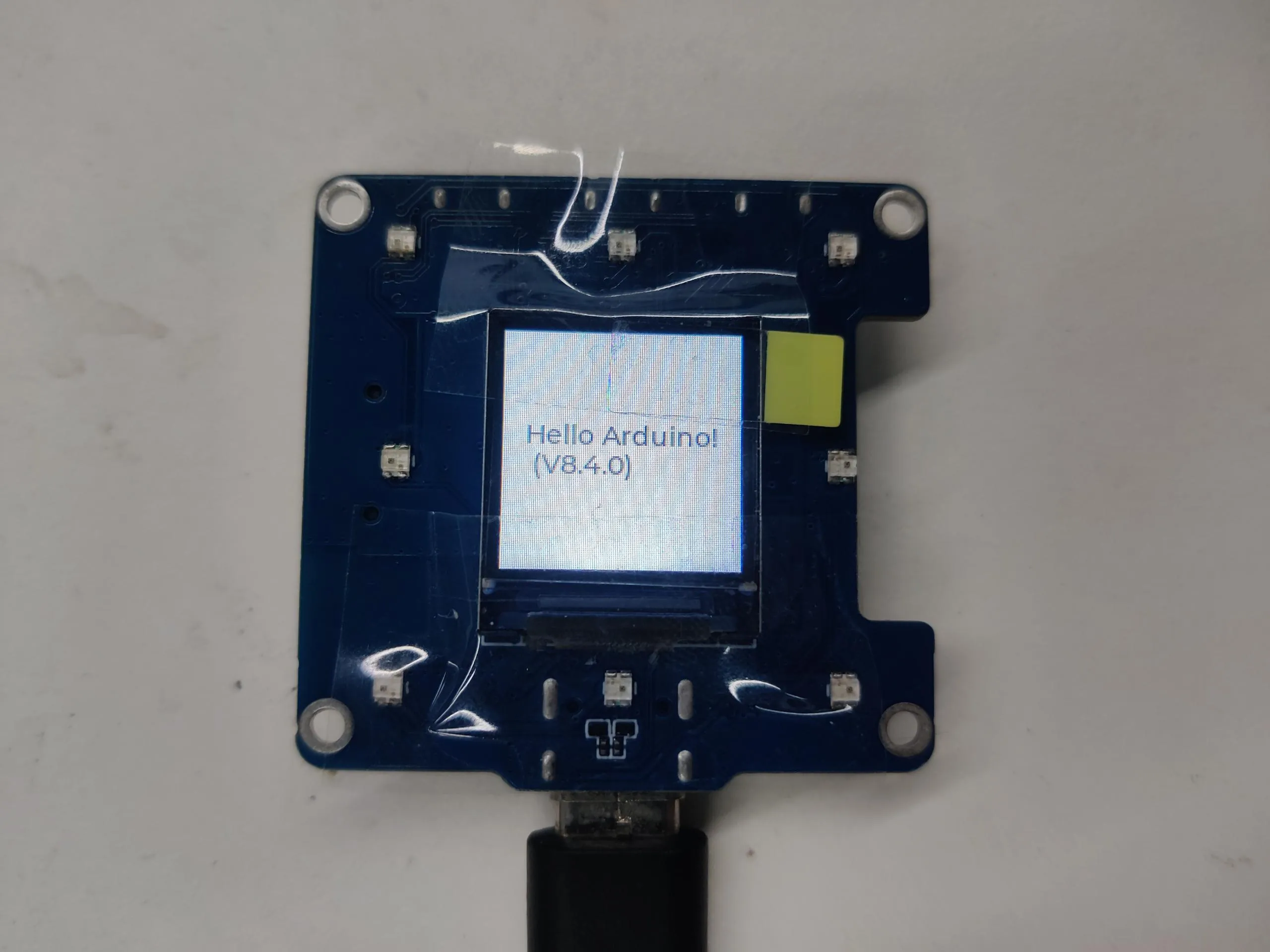
This example demonstrates how to run the lvgl examples (v8.4.0) on the ESP32-C6-LCD-0.85.
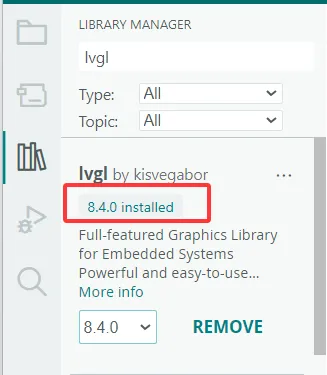
- It is required to install lvgl v8.4.0 version. If you have installed other version, please reinstall.
Operation Result
- The screen displays as follows:
09_lvgl_example_v9
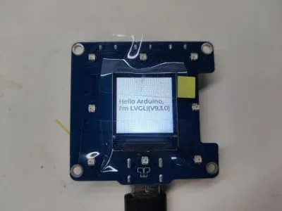
This example demonstrates how to run the lvgl (v9.3.0) examples on the ESP32-C6-LCD-0.85.
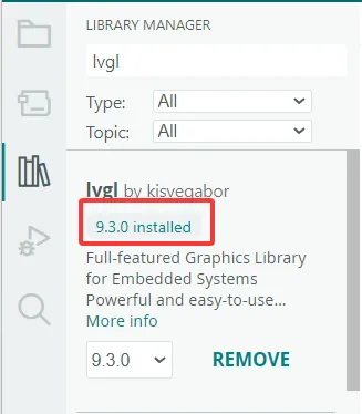
- It is required to install lvgl v9.3.0 version. If you have installed other version, please reinstall.
Operation Result
- The screen displays as follows:
ESP-IDF
This chapter contains the following sections. Please read as needed:
ESP-IDF Getting Started
New to ESP32 ESP-IDF development and looking to get started quickly? We have prepared a general Getting Started Tutorial for you.
- Section 1: Environment Setup
- Section 2: Running Examples
- Section 3: Creating a Project
- Section 4: Using Components
- Section 5: Debugging
- Section 6: FreeRTOS
- Section 7: Peripherals
- Section 8: Wi-Fi Programming
- Section 9: BLE Programming
Please Note: This tutorial uses the ESP32-S3-Zero as a teaching example, and all hardware code is based on its pinout. Before you start, it is recommended that you check the pinout of your development board to ensure the pin configuration is correct.
Setting Up Development Environment
For the ESP32-C6-LCD-0.85 development board, ESP-IDF version V5.5.0 or above is required.
The following guide uses Windows as an example, demonstrating development using VS Code + the ESP-IDF extension. macOS and Linux users should refer to the official documentation.
The screenshots in this section use ESP-IDF V5.5.2 as an example. When installing, please select the ESP-IDF version that matches your board's example.
Install the ESP-IDF Development Environment
Download the installation manager from the ESP-IDF Installation Manager page. This is Espressif's latest cross-platform installer. The following steps demonstrate how to use its offline installation feature.
Click the Offline Installer tab on the page, then select Windows as the operating system and the ESP-IDF version you need (the version shown in the screenshot is for reference only — choose the version that fits your actual needs).
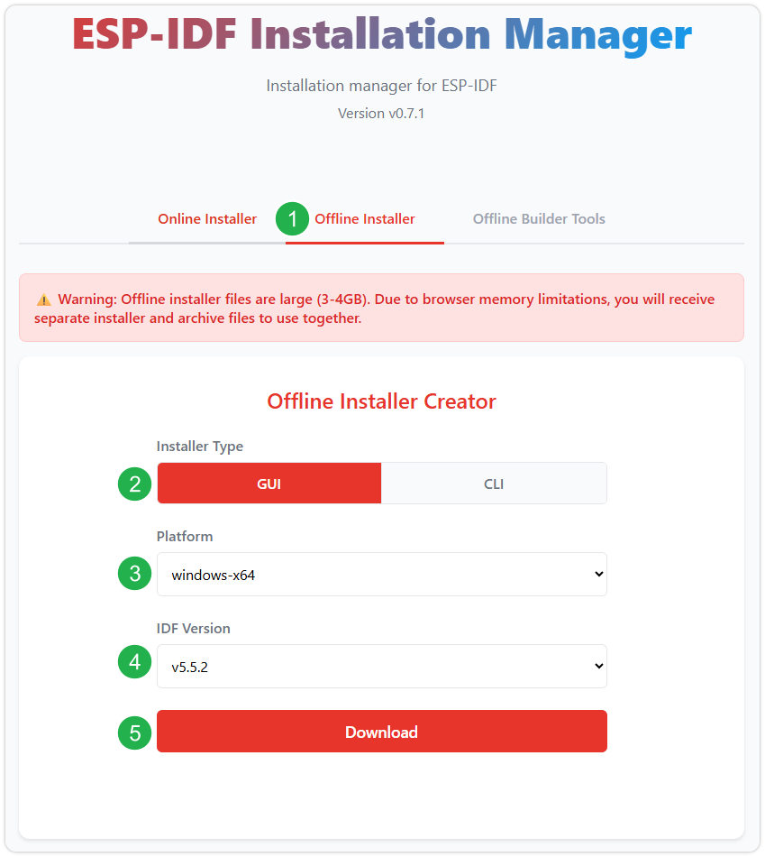
After confirming your selection, click the download button. The browser will automatically download two files: the ESP-IDF Offline Package (.zst) and the ESP-IDF Installer (.exe).
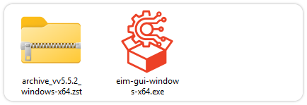
Please wait for both files to finish downloading.
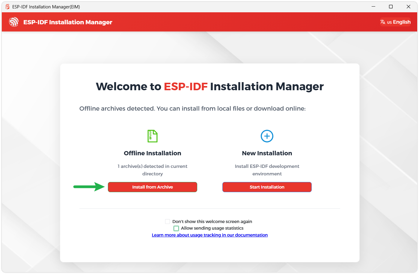
Once the download is complete, double-click to run the ESP-IDF Installer (eim-gui-windows-x64.exe).
The installer will automatically detect if the offline package exists in the same directory. Click Install from archive.
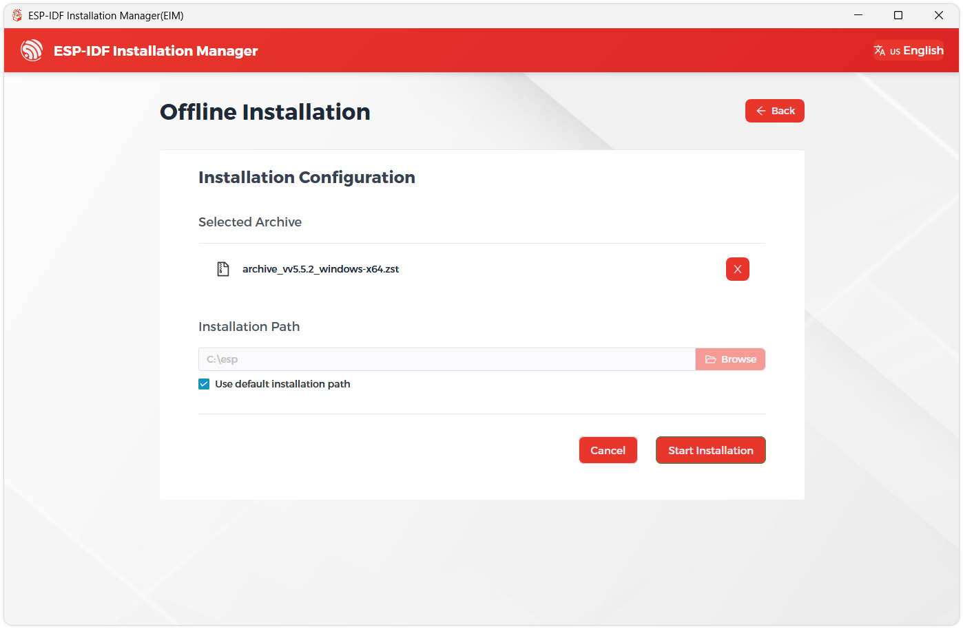
Next, select the installation path. We recommend using the default path. If you need to customize it, ensure the path does not contain Chinese characters or spaces. Click Start installation to proceed.
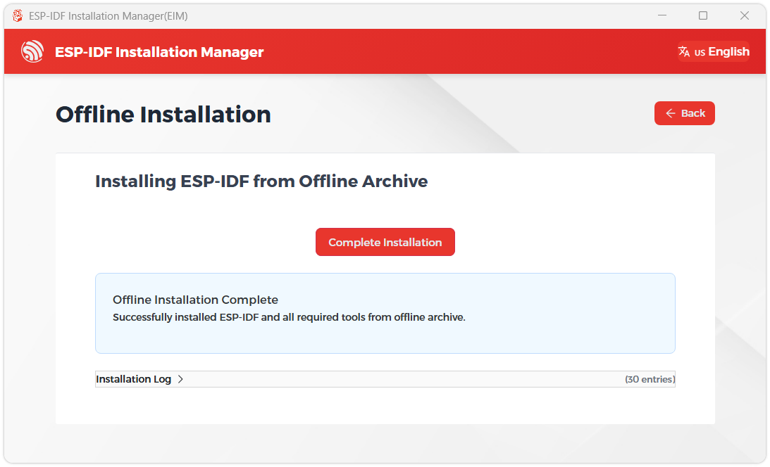
When you see the following screen, the ESP-IDF installation is successful.
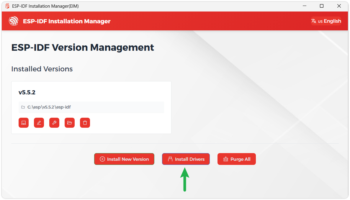
We recommend installing the drivers as well. Click Finish installation, then select Install driver.
Install Visual Studio Code and the ESP-IDF Extension
Download and install Visual Studio Code.
During installation, it is recommended to check Add "Open with Code" action to Windows Explorer file context menu to facilitate opening project folders quickly.
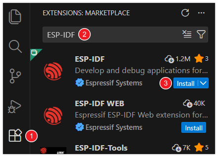
In VS Code, click the Extensions icon
 in the Activity Bar on the side (or use the shortcut Ctrl + Shift + X) to open the Extensions view.
Enter ESP-IDF in the search box, locate the ESP-IDF extension, and click Install.
For ESP-IDF extension versions ≥ 2.0, the extension will automatically detect and recognize the ESP-IDF environment installed in the previous steps, requiring no manual configuration.
Example
The ESP-IDF examples are located in the ESP-IDF directory of the example package.
01_factory
This example demonstrates a comprehensive example for the ESP32-C6-LCD-0.85, and it is also the factory default flashed example.
Specific Operations
- Press and hold the left button for 2 seconds to start recording. It records for 3 seconds. Press and hold the left button again to play the recording (if noise occurs, flash the latest firmware
\Firmware\01_factory.bin). - When powered by a battery, press and hold the middle button to shut down; short‑press to turn on.
- Long press the right button, the LED lights up and cycles through 4 colors; long press again to turn off the LED
- Click the left or right button to switch pages
Operation Result
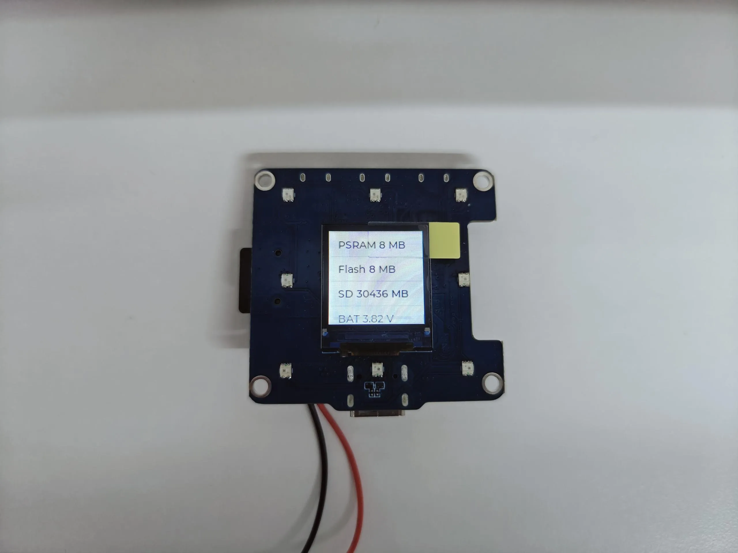
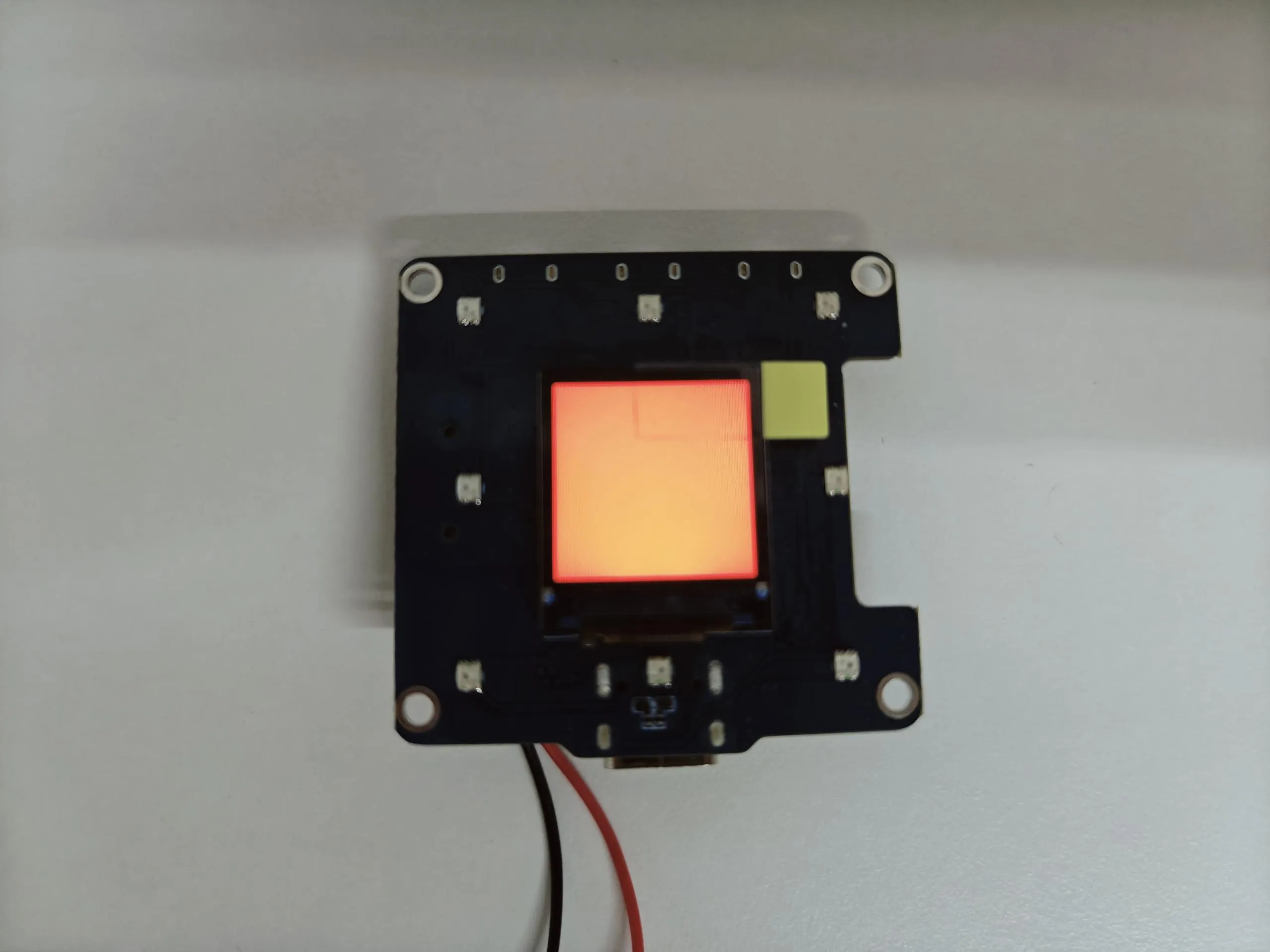
- The first page cycles through the colors red, green, and blue
- The second page displays development board information
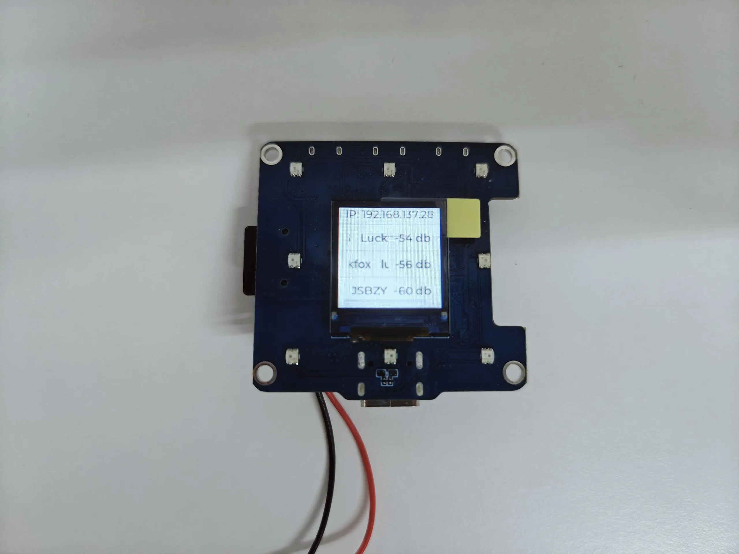
- The third page displays the IP address of the connected WiFi (if not connected or connection fails, it shows 0.0.0.0) and the scanned WiFi networks
   |
|---|
02_button_example
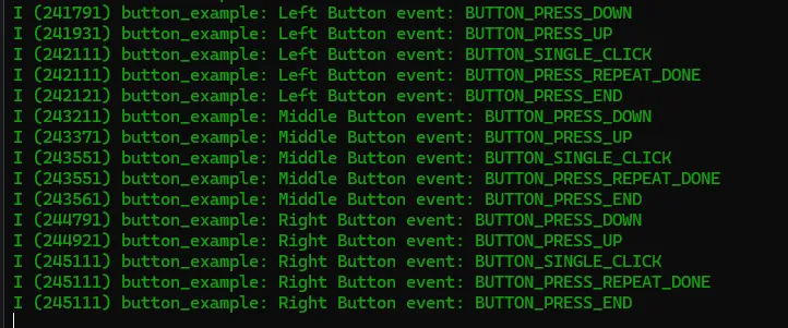
This example demonstrates how to use the espressif/button library to read button states such as single click, double click, and long press, and print them via serial port.
Code Analysis
Bind callback functions:
ret = iot_button_register_cb(boot_btn, BUTTON_PRESS_DOWN, NULL, button_event_cb, NULL);ret |= iot_button_register_cb(boot_btn, BUTTON_PRESS_UP, NULL, button_event_cb, NULL);ret |= iot_button_register_cb(boot_btn, BUTTON_PRESS_REPEAT, NULL, button_event_cb, NULL);ret |= iot_button_register_cb(boot_btn, BUTTON_PRESS_REPEAT_DONE, NULL, button_event_cb, NULL);ret |= iot_button_register_cb(boot_btn, BUTTON_SINGLE_CLICK, NULL, button_event_cb, NULL);ret |= iot_button_register_cb(boot_btn, BUTTON_DOUBLE_CLICK, NULL, button_event_cb, NULL);ret |= iot_button_register_cb(boot_btn, BUTTON_LONG_PRESS_START, NULL, button_event_cb, NULL);ret |= iot_button_register_cb(boot_btn, BUTTON_LONG_PRESS_HOLD, NULL, button_event_cb, NULL);ret |= iot_button_register_cb(boot_btn, BUTTON_LONG_PRESS_UP, NULL, button_event_cb, NULL);ret |= iot_button_register_cb(boot_btn, BUTTON_PRESS_END, NULL, button_event_cb, NULL);
Operation Result
- Open the serial monitor
03_ws2812b_example
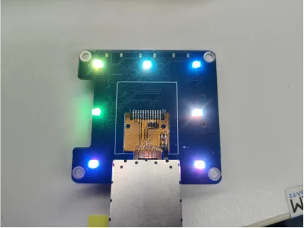
This example demonstrates how to use the ESP32's RMT peripheral to control a WS2812 LED strip, achieving LED on/off control.
Code Analysis
- Configure LED strip parameters and initialize:
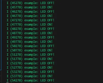
- Loop to control the LED strip's on/off state:led_strip_config_t strip_config {.strip_gpio_num = LED_STRIP_GPIO_PIN, // The GPIO that connected to the LED strip's data line.max_leds = LED_STRIP_LED_COUNT, // The number of LEDs in the strip,.led_model = LED_MODEL_WS2812, // LED strip model.color_component_format = LED_STRIP_COLOR_COMPONENT_FMT_GRB, // The color order of the strip: GRB.flags = {.invert_out = false, // don't invert the output signal}while (1) {if (led_on_off) {/* Set the LED pixel using RGB from 0 (0%) to 255 (100%) for each color */for (int i = 0; i < LED_STRIP_LED_COUNT; i++) {ESP_ERROR_CHECK(led_strip_set_pixel(led_strip, i, 5, 5, 5));}/* Refresh the strip to send data */ESP_ERROR_CHECK(led_strip_refresh(led_strip));ESP_LOGI(TAG, "LED ON!");}else{ESP_ERROR_CHECK(led_strip_clear(led_strip));ESP_LOGI(TAG, "LED OFF!");}led_on_off = !led_on_off;vTaskDelay(pdMS_TO_TICKS(500));}
Operation Result
- The screen shows no output
- The LED beads will blink simultaneously at 500ms intervals
- Open the serial monitor
04_sd_card_test
This example tests the TF card read/write functionality on the ESP32-C6-LCD-0.85.
- Insert the TF card into the card slot (TF card needs to be formatted as FAT32)
Code Analysis
Initialize and mount the TF card:
sdmmc_slot_config_t slot_config = SDMMC_SLOT_CONFIG_DEFAULT();#if EXAMPLE_IS_UHS1slot_config.flags |= SDMMC_SLOT_FLAG_UHS1;#endif// Set bus width to use:#ifdef CONFIG_EXAMPLE_SDMMC_BUS_WIDTH_4slot_config.width = 4;#elseslot_config.width = 1;#endif// On chips where the GPIOs used for the TF card can be configured, set them in// the slot_config structure:#ifdef CONFIG_SOC_SDMMC_USE_GPIO_MATRIXslot_config.clk = CONFIG_EXAMPLE_PIN_CLK;slot_config.cmd = CONFIG_EXAMPLE_PIN_CMD;slot_config.d0 = CONFIG_EXAMPLE_PIN_D0;#ifdef CONFIG_EXAMPLE_SDMMC_BUS_WIDTH_4slot_config.d1 = CONFIG_EXAMPLE_PIN_D1;slot_config.d2 = CONFIG_EXAMPLE_PIN_D2;slot_config.d3 = CONFIG_EXAMPLE_PIN_D3;#endif // CONFIG_EXAMPLE_SDMMC_BUS_WIDTH_4#endif // CONFIG_SOC_SDMMC_USE_GPIO_MATRIX// Enable internal pullups on enabled pins. The internal pullups// are insufficient however, please make sure 10k external pullups are// connected on the bus. This is for debug / example purpose only.slot_config.flags |= SDMMC_SLOT_FLAG_INTERNAL_PULLUP;ESP_LOGI(TAG, "Mounting filesystem");ret = esp_vfs_fat_sdmmc_mount(mount_point, &host, &slot_config, &mount_config, &card);
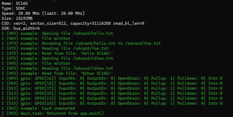
Operation Result
- Open the serial monitor
- Print TF card information
05_lvgl_example
This example demonstrates how to run the lvgl examples (LVGL v8 and LVGL v9) on the ESP32-C6-LCD-0.85.
Code Analysis
Initialize:
/* LCD HW initialization */ESP_ERROR_CHECK(app_lcd_init());/* Touch initialization */app_touch_init();/* LVGL initialization */ESP_ERROR_CHECK(app_lvgl_init());
Operation Result
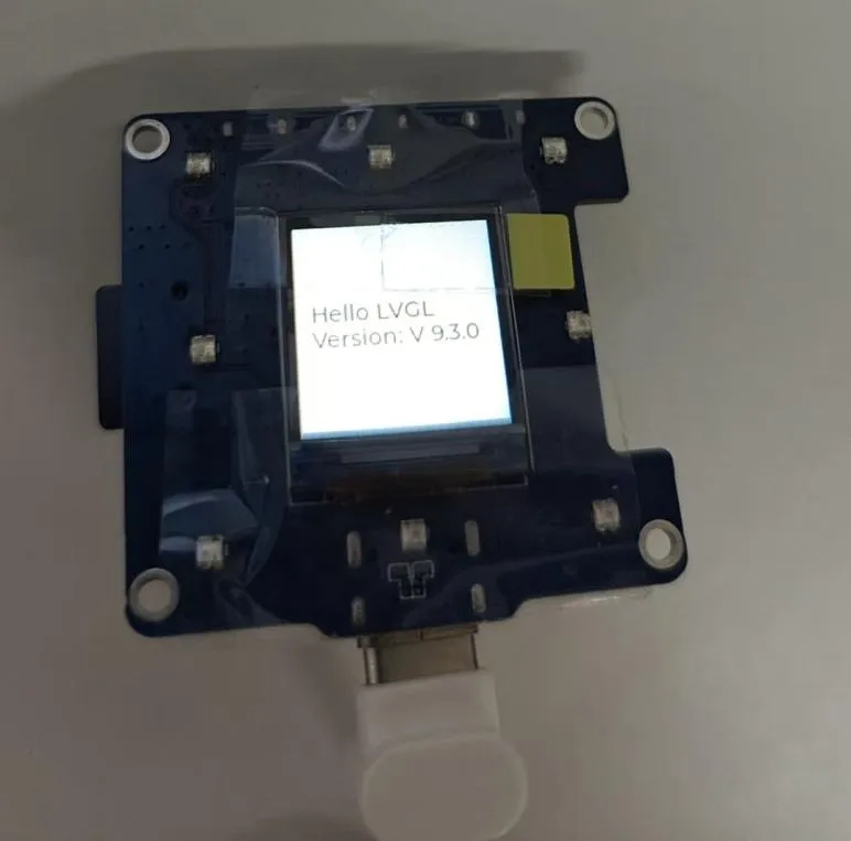
- The default LVGL version used is v9.3.0. To change the version, modify the LVGL configuration in the
main/idf_component.ymlfile, for example, change it tolvgl/lvgl:^8.4.0.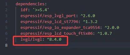
- Operation effect
Resources
1. Hardware Resources
Development Board Design Files
2. Technical Manuals
ESP32-C6 Chip Official Manuals
Onboard Component Datasheets
3. Example
4. Software Tools
- Arduino:
- VS Code:
- Debugging Tools:
- Firmware Flashing Tool:
- Other Resource Links:
Support
Monday-Friday (9:30-6:30) Saturday (9:30-5:30)
Email: services01@spotpear.com
[Tutorial Navigation]
- Features
- Onboard Resources
- Pinout Definition
- Dimensions
- User Guide
- Assembly Guide
- XiaoZhi AI Application Tutorial
- 0. Firmware Flashing Process Reference
- 1. Flashing Without a Development Environment
- 2. Flashing with ESP-IDF Environment
- 2.1 Download the Project from XiaoZhi GitHub
- 2.2 Environment Setup
- 2.3 Configuration and Compilation
- 2.4 Start Network Provisioning
- 2.5 Add a New Device to the Management Console
- 3. XiaoZhi Resources
- Working with Arduino
- Arduino Getting Started
- Setting Up Development Environment
- Example
- ESP-IDF
- Resources
- Support