


- sales/support
Google Chat:---
- sales
+86-0755-88291180
- sales01
sales@spotpear.com
- sales02
dragon_manager@163.com
- support
tech-support@spotpear.com
- CEO-Complaints
zhoujie@spotpear.com
- Only Tech-Support
WhatsApp:13246739196
- Purchase/Shipping/Refund
WhatsApp:13424403025
- HOME
- >
- ARTICLES
- >
- Common Moudle
- >
- UART Module
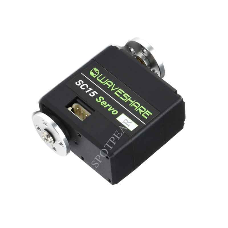
SC15 Servo User Guide
Introduction
As a kind of high-torque programmable serial bus servo, it can control the angle within 180° and can switch to the motor/stepper motor mode that can be rotated continuously through the program. There are two interfaces on each servo, which can be used in series. In theory, 253 bus servos can be controlled at the same time, and each servo can obtain information such as the current angle, load, voltage, mode, and so on. It is suitable for robot projects that require feedback on the angle and load of the steering gear, such as robotic arms, hexapod robots, humanoid robots, wheeled robots, etc.
Specification
- Input Voltage: 4.8-8.4V
- Mechanical Limited Angle: No Limit
- Rotating Angle: 180° (servo mode angle control) / 360° (motor mode continuous rotation)
- Baudrate: 1Mbps
- Gear:high precision metal gear
- Idling Speed: 0.18sec / 60°@4.8V 0.16sec / 60°@6V
- Pos Sensor Resolution: 180° / 1024
- ID Range: 0-253
- Feedback: Position, Load, Speed, Input Voltage
- Idling Current: 200 mA
- Stalling Current: 1700 mA
- Dimension: 40.5mm x 40mm x 20mm
Feature
- Up to 253 servos can be connected in series at the same time(requires full power), also can obtain feedback information from each servo.
- Wide-range input voltage: 4.8-8.4V.
- Large Torque, Up To 17kg.Cm Torque On 8.4V Voltage.
- High precision, the angle control accuracy reaches 180°/1024.
- The working mode can be set by the program: servo mode angle control/motor mode (can rotate continuously).
Open Source Project
You can download the relevant open-source robot models in the product documentation for building your own projects.
User Guides of Hardware
- You can use Servo Driver Expansion Board to control the servo.
- If you want to use the servo in your project, you can refer to the following schematic diagram: Servo Schematic
Product Usage Tutorial
- The following tutorial uses servo driver by default to explaining how to use the servo, if you need to use it in your own project, you can refer to the sample program and the bus servo drive circuit schematic for secondary development.
- The factory default ID of the servo is 1. Among the servos connected to the same servo drive board, the same ID can only correspond to one servo, and there cannot be more than one servo with the same ID in the one control circuit. When you set the ID for the servo, try to ensure that only one servo whose ID is to be changed is connected to the driver board. After the ID is changed, it will be permanently saved in the servo and will not be lost even if the power is off.
- First of all, you need to set an independent ID for each servo. When setting an ID for one servo, the driver board should not be connected to other servos.
- If you use the SC15 servo, after connecting it to the driver board, you need to provide 4.8-8.4V via the DC port (5.5*2.1mm) on the board, and the port will directly power the servo. If you use a large number of servos, you need to provide enough currents for the port.
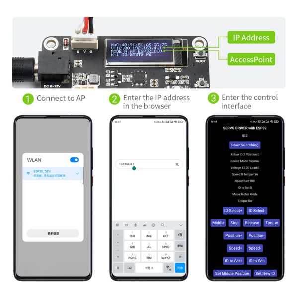
- After the driver board is powered on, a WiFi hotspot will be created by default. The default hotspot name is ESP32_DEV, and its password is 12345678. Please connect to this hotspot with your phone.
- After connecting to the hotspot issued by the servo driver board, it is recommended to use Google Chrome to access the address 192.168.4.1. Noted that the phone will fail to verify the server with ping after connecting the WiFi, so it may automatically switch to the other known WiFi. In this case, you should connect ESP32_DEV again, and the phone will not connect to other WiFi automatically after the reconnection is successful.
- The driver board will automatically scan the servo ID (0-20) when it is powered on (in order to save the boot time). If your servo ID is more than 20, you must change the MAX_ID value in ServoDriverST.ino and upload it to the driver board again. For the specific method of uploading the program to the ESP32, please refer to the chapter on how to use the software later.
- If the servo is connected after the driver board is powered on, you need to click Start Searchingon the mobile browser page to scan again.
- Active IDis the currently selected servo ID number, ID to Setis the new ID number to be set, adjust the value of ID to Setthrough ID to Set+andID to Set-, and press the Set New ID button to set the servo ID Active ID as ID to Set.
- When the IDs of all servos are set, you can connect them all. If you do not restart the device, you need to clickStart Searchingto scan all servos.
- ID: shows all ID numbers of servos currently connected to the servo driver board.
- Active ID The currently selected servo ID number, and the subsequent operations are all controlling thisActive ID servo.
- You can select the Active ID servo via the ID to Set+ and ID to Set- buttons.
- Middlekey, you can turn the servo to the middle position, the position range of the servo is 0-1024, and the middle position is 1023.
- Stopkey, the default program will not let the servo move all the time. If the servo cannot be stopped after the secondary development, you can press the Stop key to hault the servo movement.
- Releasekey, press it and the servo will close torque lock (Torque Off), then you can turn the servo by hand.
- Torquekey, after pressing the servo, the servo will turn on the torque lock (Torque On), at this time, the servo will maintain the specified position with force.
- Position+key, after pressing the servo, the servo will start to rotate clockwise. When the servo is in the servo mode, it will not continue to rotate after turning to the 4095 position.
- Position-key, after pressing the servo, the servo will start to rotate counterclockwise. When the servo is in the servo mode, it will not continue to rotate after turning to the 0 position.
- Speed+ and Speed- are used to set the speed of the servo. The maximum setting for ST series servos is about 3073. The speed is the number of steps per second, 50 steps/sec≈0.732RPM.
- Set Middle Positionkey, this function is not applicable to SC series servos.
- Set Servo Modekey, set the servo to servo mode, 180° absolute angle control can be performed in the servo mode, the setting will be permanently saved and will not be lost even if the power is turned off.
- Set Motor Modekey, set the servo to stepper motor mode, the servo can rotate continuously 30,000 steps. If you press it continuously, the motor will keep rotating. This mode can control the relative angle within ±7 circles and the number of circles will not be saved when power is off, but the stepper motor mode settings will be permanently saved even if power is off.
- Start Serial Forwardingbutton, set the servo driver board to serial forwarding mode, you can directly control the servo and get the feedback of the servo with the typeC interface on the board. This function is used to debug the servo.
- Normalkey, set the servo driver board to normal mode, in this mode, it will not send or receive any information via ESP-NOW.
- Leaderkey, set the servo driver board as the host, in this mode, the driver board continuously sends the ID, position, and speed of the current Active ID servo to the driver board of the controlled slave through the ESP-NOW protocol. After the servo driver board is turned on, the MAC:on the first line of the screen is the MAC address of this development board, which is unique, such as MAC: 08 3A F2 93 5F A8. The premise of ESP-NOW communication is to get the MAC address of the slave, please write down the address, and fill it in the broadcastAddress[] = {0x08, 0x3A, 0xF2, 0x93, 0x5F, 0xA8} of ServoDriverST.ino, then upload it to the driver of the host and the function is enabled.
- Followerkey, set the servo drive board as the slave, after changing the MAC address of the slave in the program of the host, it can act under the remote control of the host.
- RainbowONand RainbowOFFkeys are used to turn on and off the rainbow effect of RGB lights.
User Guides of Software
How to use Arduino IDE:
- Download the sample program zip package: sample program
- After unzipping, copy the SCServo folder to \Documents\Arduino\libraries to install the library for controlling the servos.
- You can refer to the demos in \examples\arduinoIDE\SCSCL to learn how to control servos and get feedback information from the servo. The functions described below provide graphical interface demos in the Servo Driver Expansion Board, which are novice-friendly.
- Servo Initialization
Each program that controls the steering gear needs to initialize the steering gear before it can be used.
#include <SCServo.h>
 SCSCL sc;
 void setup(){
         Serial1.begin(1000000); //Initialize the serial port, if you use ESP32 and other devices, you can also custom the serial ports
         // Serial1.begin(1000000, SERIAL_8N1, RX, TX); // custom serial port
         sc.pSerial = &Serial1;
         while(!Serial1) {}
}- Change Servo ID
In the servos connected in series, each ID can only correspond to one servo, or the information fed back by the servos cannot be obtained normally. When changing the servo ID, try to ensure that the driver board is only connected to one servo, and the ID will be permanently saved in the servos:
#include <SCServo.h>
 SCSCL sc;
 int ID_ChangeFrom = 1;   // The original ID of the servo to change the ID, the factory default is 1
 int ID_Changeto      = 2;   // New ID
 void setup(){
   Serial1.begin(1000000);
   sc.pSerial = &Serial1;
   while(!Serial1) {}
   sc.unLockEprom(ID_ChangeFrom); //Unlock EPROM-SAFE
   sc.writeByte(ID_ChangeFrom, SCSCL_ID, ID_Changeto);//Change ID
   sc.LockEprom(ID_Changeto); //EPROM-SAFE lock
 }
 void loop(){
}- Ping
Used to test whether a servo is connected normally.
#include <SCServo.h>
 SCSCL sc;
 int TEST_ID = 3; // Servo ID to test
 void setup()
 {
   Serial.begin(115200);
   Serial1.begin(1000000, SERIAL_8N1, RX, TX); // custom serial port
   sc.pSerial = &Serial1;
   while(!Serial1) {}
 }

 void loop()
 {
   int ID = sc.Ping(TEST_ID);
   if(ID!=-1){
     Serial.print("Servo ID:");
     Serial.println(ID, DEC);
     delay(100);
   }else{
     Serial.println("Ping servo ID error!");
     delay(2000);
   }
}- Write Position
Can be used to control the rotation of individual servos
#include <SCServo.h>
 SCSCL sc;
 void setup()
 {
   Serial1.begin(1000000);
   sc.pSerial = &Serial1;
   while(!Serial1) {}
 }
 void loop()
 {
   sc.WritePos(1, 1000, 0, 1500); // Control the servo with ID of 1 to rotate to 1000 at a speed of 1500.
   delay(754);//[(P1-P0)/V]*1000+100

   sc.WritePos(1, 20, 0, 1500); // Control the servo with ID of 1 to rotate to 20 at a speed of 1500.
   delay(754);//[(P1-P0)/V]*1000+100
}- Synchronous Write
Can be used to control multiple servos at the same time (turn to different positions and different speeds).
#include <SCServo.h>
 SCSCL sc;
 byte ID[2];
 u16 Position[2];
 u16 Speed[2];
 void setup()
 {
  Serial1.begin(1000000);
  sc.pSerial = &Serial1;
  delay(1000);
  ID[0] = 1;
  ID[1] = 2;
 }
 void loop()
 {
  Position[0] = 1000;
  Position[1] = 1000;
  Speed[0] = 1500;
  Speed[1] = 1500;
  sc.SyncWritePos(ID, 2, Position, 0, Speed);//Servo((ID1/ID2)) moves at max speed=1500, moves to position=1000.
  delay(754);//[(P1-P0)/V]*1000+100
  Position[0] = 20;
  Position[1] = 20;
  Speed[0] = 1500;
  Speed[1] = 1500;
  sc.SyncWritePos(ID, 2, Position, 0, Speed);//Servo((ID1/ID2)) moves at max speed=1500, moves to position=20.
  delay(754);//[(P1-P0)/V]*1000+100
}- Get Servo Information Feedback
#include <SCServo.h>
 SCSCL sc;
 int ID_input = 1;
 void setup()
 {
  Serial1.begin(1000000, SERIAL_8N1, S_RXD, S_TXD);
  Serial.begin(115200);
  sc.pSerial = &Serial1;
  delay(1000);
 }

 void loop()
 {
  int Pos;
  int Speed;
  int Load;
  int Voltage;
  int Temper;
  int Move;
  if(sc.FeedBack(ID_input)!=-1){
    Pos = sc.ReadPos(-1);
    Speed = sc.ReadSpeed(-1);
    Load = sc.ReadLoad(-1);
    Voltage = sc.ReadVoltage(-1);
    Temper = sc.ReadTemper(-1);
    Move = sc.ReadMove(-1);
    Serial.print("Position:");
    Serial.println(Pos);
    Serial.print("Speed:");
    Serial.println(Speed);
    Serial.print("Load:");
    Serial.println(Load);
    Serial.print("Voltage:");
    Serial.println(Voltage);
    Serial.print("Temper:");
    Serial.println(Temper);
    Serial.print("Move:");
    Serial.println(Move);
    delay(10);
  }else{
    Serial.println("FeedBack err");
    delay(500);
  }

  Pos = sc.ReadPos(1);
  if(Pos!=-1){
    Serial.print("Servo position:");
    Serial.println(Pos, DEC);
    delay(10);
  }else{
    Serial.println("read position err");
    delay(500);
  }

  Voltage = sc.ReadVoltage(1);
  if(Voltage!=-1){
  Serial.print("Servo Voltage:");
    Serial.println(Voltage, DEC);
    delay(10);
  }else{
    Serial.println("read Voltage err");
    delay(500);
  }

  Temper = sc.ReadTemper(1);
  if(Temper!=-1){
    Serial.print("Servo temperature:");
    Serial.println(Temper, DEC);
    delay(10);
  }else{
    Serial.println("read temperature err");
    delay(500);
  }

  Speed = sc.ReadSpeed(1);
  if(Speed!=-1){
    Serial.print("Servo Speed:");
    Serial.println(Speed, DEC);
    delay(10);
  }else{
    Serial.println("read Speed err");
    delay(500);
  }

  Load = sc.ReadLoad(1);
  if(Load!=-1){
    Serial.print("Servo Load:");
    Serial.println(Load, DEC);
    delay(10);
  }else{
    Serial.println("read Load err");
    delay(500);
  }

  Move = sc.ReadMove(1);
  if(Move!=-1){
    Serial.print("Servo Move:");
    Serial.println(Move, DEC);
    delay(10);
  }else{
    Serial.println("read Move err");
    delay(500);
  }
  Serial.println();
} 