


- sales/support
Google Chat:---
- sales
+86-0755-88291180
- sales01
sales@spotpear.com
- sales02
dragon_manager@163.com
- support
tech-support@spotpear.com
- CEO-Complaints
zhoujie@spotpear.com
- Only Tech-Support
WhatsApp:13246739196
- Purchase/Shipping/Refund
WhatsApp:13424403025
Raspberry Pi Pico RGB-Matrix-P3-64x32 User Guide
Introduction
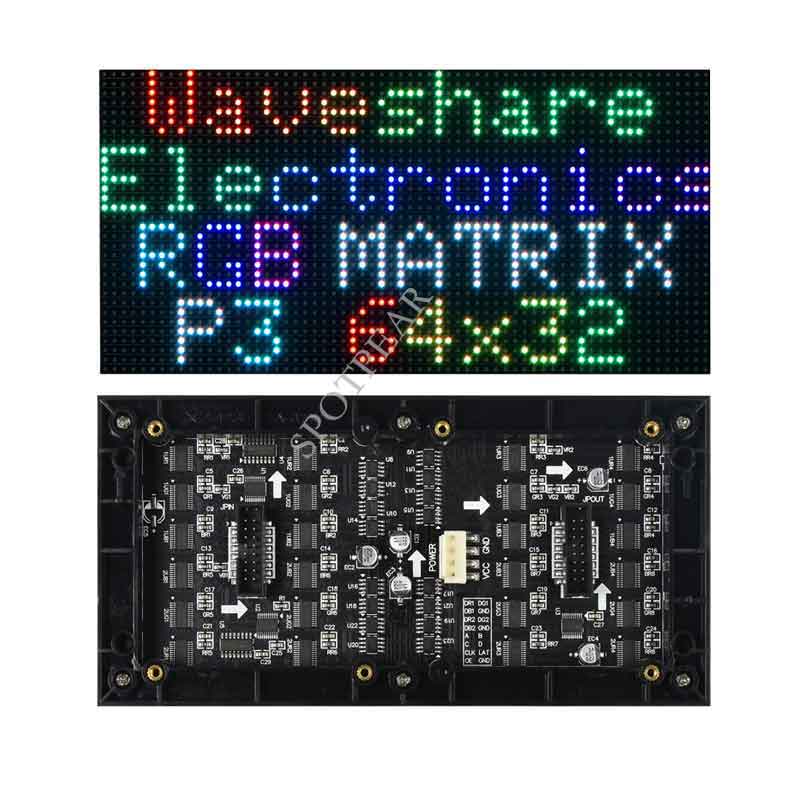
RGB Full-Color LED Matrix Panel, 64 × 32 Pixels, Adjustable Brightness
Features
- 2048 individual RGB LEDs, full-color display, adjustable brightness.
- 64 x 32 pixels, 3mm pitch, allows displaying text, colorful images, or animation.
- 192 x 96mm dimensions, moderate size, suitable for DIY desktop display or wall mount display.
- Onboard two HUB75 headers, one for controller data input, one for output, and chain support.
- Provides open-source development resources and tutorials, for use with Raspberry Pi, Pico, ESP32, Arduino, and so on.
Specifications
| DIMENSIONS | 192mm × 96mm |
|---|---|
| PIXELS | 64 × 32=2048 DOTS |
| PITCH | 3mm |
| PIXEL FORM | 1R1G1B |
| VIEWING ANGLE | ≥160° |
| CONTROL TYPE | synchronization |
| DRIVING | 1/16 scan |
| HEADER | HUB75 |
| POWER SUPPLY | 5V / 2.5A(VH4 header input) |
| POWER | ≤12W |
Header Definition
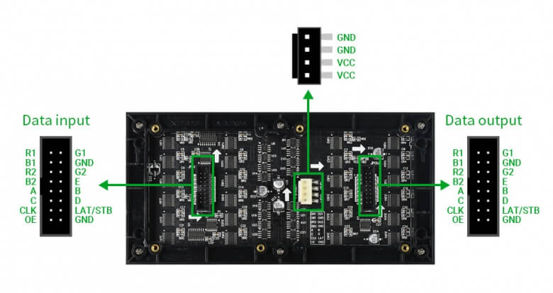
| PIN | DESCRIPTION | PIN | DESCRIPTION | |
|---|---|---|---|---|
| VCC | 5V power input | GND | Ground | |
| R1 | R higher bit data | R2 | R lower bit data | |
| G1 | G higher bit data | G2 | G lower bit data | |
| B1 | B higher bit data | B2 | B lower bit data | |
| A | A line selection | B | B line selection | |
| C | C line selection | D | D line selection | |
| E | E line selection | CLK | clock input | |
| LAT/STB | latch pin | OE | output enable |
Note: The power supply port (VCC and GND) of the display is 5V, do not connect to other power supply voltages, or you will burn the display.
Usage Scenarios
DIY Maker Desktop Or Wall Mount Display, Signboard, Environment Monitor...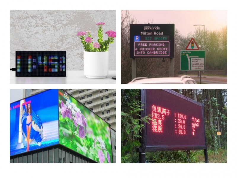
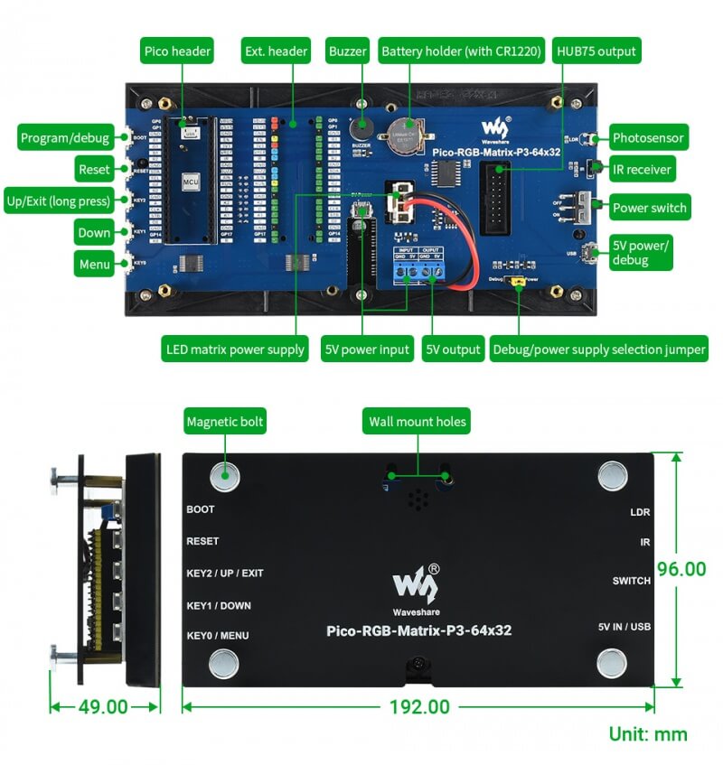
Hardware Introduction
Introduction to Floor Resources
Directions for Raspberry Pi
Please refer to github information: Demo, wiring reference
If the overall brightness of the indicator is dim, click setting to set the brightness.
User Guides for Pico
Pico connection pins
| Board | Pico | Pin description |
|---|---|---|
| Pins used by RGB LED Matrix (HUB75 interface) | ||
| R1 | GP02 | R higher bit data |
| G1 | GP03 | G higher bit data |
| B1 | GP04 | B higher bit data |
| R2 | GP05 | R lower bit data |
| G2 | GP08 | G lower bit data |
| B2 | GP09 | B lower bit data |
| A | GP10 | A line selection |
| B | GP16 | B line selection |
| C | GP18 | C line selection |
| D | GP20 | D line selection |
| E | GP22 | E line selection |
| CLK | GP11 | clock input |
| STB/LAT | GP12 | latch pin |
| OE | GP13 | output enable |
| Board | Pico | Pin description |
|---|---|---|
| Pins used by other resources of the board | ||
| K0 | GP15 | KEY0 button, the MENU menu of the digital clock, can also be customized |
| K1 | GP19 | KEY1 button, + / Down button of digital clock, can also be customized |
| K2 | GP21 | KEY2 button,-/ UP button of digital clock, can also be customized |
| RUN | RUN | RESET button, can be used for Pico reset |
| BOOTSET | BOOTSET | BOOT button, can be used for Pico burning program (long press BOOT, then press RESET to enter the firmware download mode) |
| SDA | GP06 | I2C data pin, used to control DS3231 RTC clock chip |
| SCL | GP07 | I2C clock pin, used to control DS3231 RTC clock chip |
| BUZZ | GP27 | Buzzer control pin |
| AIN | GP26 | Photoresistor control pin |
| IRM | GP28 | Infrared receiving control pin |
See detailed hardware design of the circuit diagram.
Hardware Connection
Materials needed
- Pico-RGB-Matrix-P3-64 x 32 (this product).
- Raspberry Pi Pico (must be purchased separately, if not, it is recommended to buy a version with soldered headers, which is convenient for direct insertion and use).
- Micro USB cable (must be purchased separately).
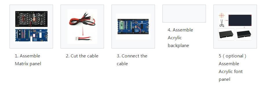
Hardware connection steps
- Align the pin header which is marked in red and then connect the RGB LED Matrix panel to the driver board.
- Cut the adapter cable (about 10cm) by plier
- Connect the cable which is cut in the last step to the RGB LED Matrix and the driver board
- Assemble the Acrylic backplane and fix it with magnetic screws
- Optional: If you feel that the RGB LED Matrix is too bright, you can stick the black Acrylic font panel on the Matrix.
Example display
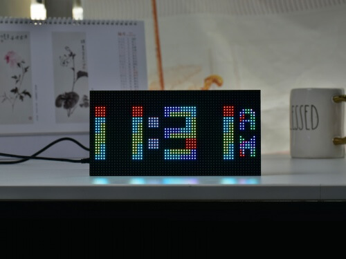
Multi-Features Digital Clock
This example is developed based on the C++ SDK. In order to quickly demonstrate the effects and functions of the example, you can skip the steps of "Building a C++ SDK Development Environment" and "Program Debugging and Development" and directly "Download and Burn the Program". After the burning is completed, the effect of the instance running is shown in the following figure:
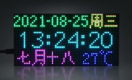
【Function Description】
- Time display screen:
- Display date, day of the week, hour, minute, lunar calendar and temperature
- Function setting menu
- Date setting
- time setting
- BEEP setting (buzzer setting)
- Auto brightness
- Language setting (under development)
Fruit machine
This example is developed based on CircuitPython[1] , and the program is downloaded[2] . The effects and functions of the example are as follows: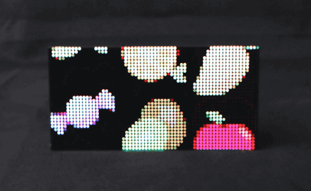
【Function Description】
- The display can display a variety of fruits or other small BMP icons
- Automatically scroll icons at regular intervals, and randomly display the results of the scrolling
- CircuitPython is a fork of MicroPython, For specific usage, please refer to the RGB-Matrix related CircuitPython tutorial
- Pico must first install CircuitPython,and then copy the corresponding CircuitPythond code to the recognized U disk to complete the download.
Infrared transceiver test
This example is developed based on CircuitPython,and the example effects and functions are as follows: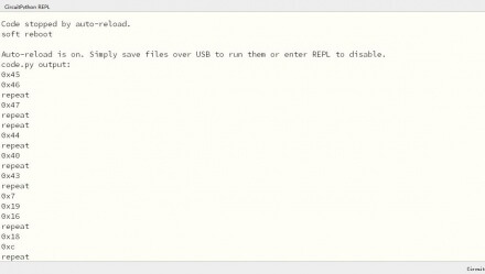
【Function Description】
- The infrared serial code generated by the corresponding button of the infrared remote control can be recognized
C++ SDK Development Tutorial
Development environment setup
For a complete tutorial on how to get started with the C/C++ SDK, You can directly refer to the Offical manual of Raspberry Pi.
Raspberry Pi development environment setup
If you plan to develop for Pico on the Raspberry Pi, you can quickly set up the C/C++ toolchain by running our "setup script" from the command line.
Instructions: Before running the installation script, you should make sure that the operating system on your Raspberry Pi is up to date.
Windows development environment setup
For Windows development environment construction, please refer to:
Download and burn programs
C++ SDK program programming
The following is an example of programming a simple "blinking LED" program:
- Download blink.uf2 ("Blink LED" flash file)
- Press and hold the BOOTSEL button, then plug the Pico into the USB port of your Raspberry Pi or other computer.
- It will be mounted as a mass storage device named "RPI-RP2". Drag and drop the blink.uf2 binary onto the "RPI-RP2" drive letter. The Pico will restart and the onboard LEDs should start blinking.
- Check out the Github source code for "Blink LED"

CircuitPython Development Tutorial
If you are not familiar with CircuitPython, you can first study the official recommended guide "Introduction to CircuitPython for Raspberry Pi Pico".
This guide covers the basics of getting started with CircuitPython and using the editor.
Development environment setup
In order to facilitate the programming, development and debugging of CircuitPython, it is recommended to use the "Mu Editor" development software. You can use Mu Editor for Pico's CircuitPython development on Windows.
The following describes the development and use of Mu Editor under Windows.
Windows development environment (Mu Editor) build and use
- Download Mu Editor and follow the steps to install
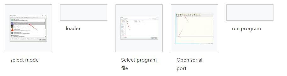
- After the installation is complete, it is the first time to configure the language and select the mode. Since we are using CircuitPython, pay attention to the mode selection CircuitPython option.
- After the configuration is complete, it will show that the device cannot be found, that is because Pico has not downloaded the CircuitPython firmware library.
- Download the CircuitPython firmware library and burn it into Pico
- Download the CircuitPython UF2 file.
- Press and hold the BOOTSEL button, then plug the Pico into the USB port of your Raspberry Pi or other computer. Release the BOOTSEL button after connecting the Pico.
- It will be mounted as a mass storage device named "RPI-RP2".
- Drag and drop the CircuitPython UF2 file onto the "RPI-RP2" volume. Your Pico will reboot, a new disk drive named CIRCUITPY will appear, and you're done.
- The new disk drive will have a default code.py file, you open it with Mu Editor, the content is: "print("Hello World!")", the specific opening steps are shown in the last figure.
- Open the serial port, click the blank area and press Ctrl+C, then press Ctrl+D or click the blank area of the code interface and press Ctrl+S to run the program. You can observe the running effect in the CircuitPython REPL window.
User Guides of ESP32-S2-Pico
Environment Setting
Our demo is based on Arduino, please refer to Arduino Environment Setting
Example
Note: A Pico baseboard is required for use here.
Click to download the programFile:Pico-RGB-Matrix-P3-64x32-Demo (5).zip, after the download is complete, go to Pico-RGB-Matrix-P3-64x32-Demo\ESP32-S2-Pico\Arduino,
1. Copy RGBMatrix-master to the libraries in the Arduino installation directory;
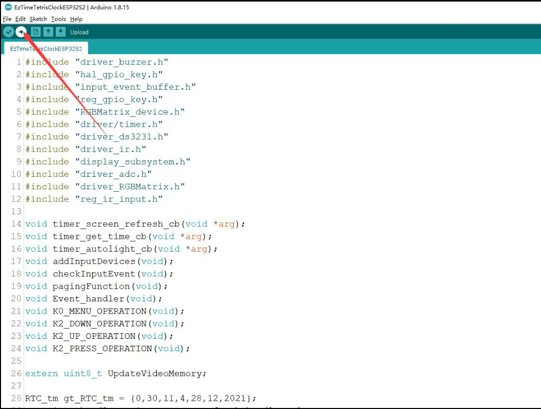
2. Go back to RGB-Matrix-P3-64x32-Demo\\ESP32-S2-Pico\Arduino, open the .ino file in EzTimeTetrisClockESP32S2 and follow the steps below to download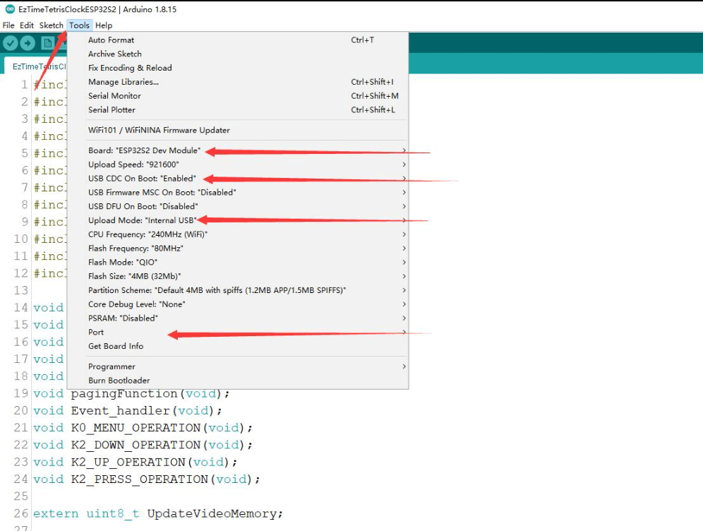
Example display
【Function Description】
- Time display screen:
- Display date, week, hour, minute, lunar calendar and temperature
- Function setting menu
- date setting
- time setting
- BEEP setting (beep setting)
- Auto Brightness
- language settings
User Guides of Arduino Mega
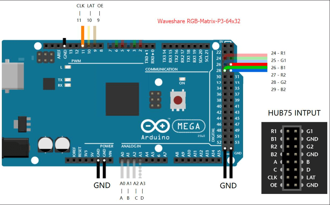
Hardware Connection
Material Needed
- RGB-Matrix-P3-64 x 32 (this product)
- Arduino Mega (sold separately)
Hardware Connection Picture
Software Setting
- Download arduino-1.8.15 (the corresponding library files have been installed)
- After connecting the wires according to the hardware connection diagram, the software settings are as follows:
Example display
RGB text display
The effect of running the example is shown in the figure below:
【Function Description】
- Display screen:
- Displayable icon
- Can display text and numbers and other text content
User Guides of ESP32
Hardware connection
Materials needed
- RGB-Matrix-P3-64x32(This product)
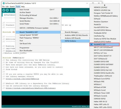
- NodeMCU-32S(To be purchased separately, if not, it is recommended to buy a version with a soldered pin header, which is convenient for direct insertion)
ESP32 connection pin correspondence
| RGB LED Matrix Pins used (HUB75 interface) | ||
|---|---|---|
| bottom plate | ESP32 | Pin description |
| R1 | GP13 | High-order R data |
| A | GP19 | A row selection |
| B | GP23 | B line selection |
| C | GP18 | C row selection |
| D | GP5 | D line selection |
| E | GP15 | E row selection |
| CLK | GP14 | Clock Input |
| STB/LAT | GP22 | Latch Pin |
| OE | GP0 | Output Enable |
| Connect data input to data output | ||
|---|---|---|
| Data Input | Data Output | Pin Description |
| G1 | R2 | High G data |
| B1 | G2 | High-order B data |
| R2 | R1 | Lower R data |
| G2 | G1 | Low G data |
| B2 | B1 | Lower B data |
Software settings
- Download arduino-1.8.15 (corresponding library files have been installed)
- After connecting the wires according to the hardware connection diagram, the software settings are as follows: