- sales/support
Google Chat:---
- sales
+86-0755-88291180
- sales01
sales@spotpear.com
- sales02
dragon_manager@163.com
- support
tech-support@spotpear.com
- CEO-Complaints
zhoujie@spotpear.com
- Only Tech-Support
WhatsApp:13246739196
- Purchase/Shipping/Refund
WhatsApp:13424403025
Raspberry Pi Stepper Motor HAT User Guide
一、Overview
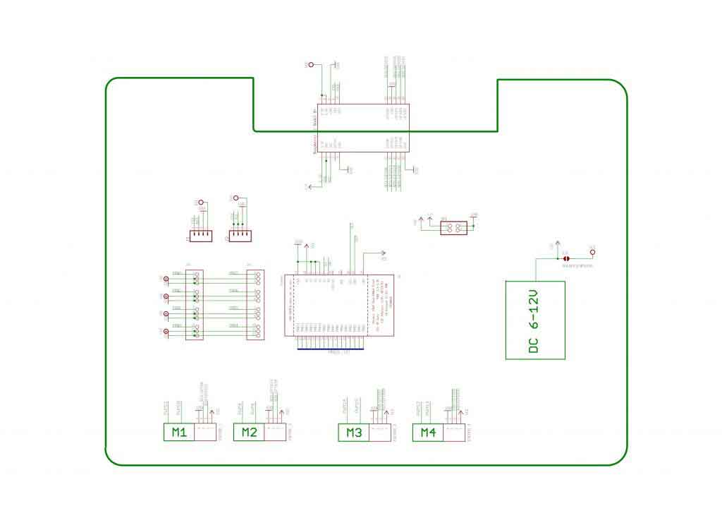
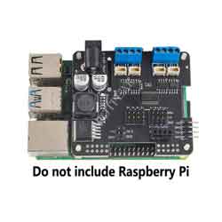
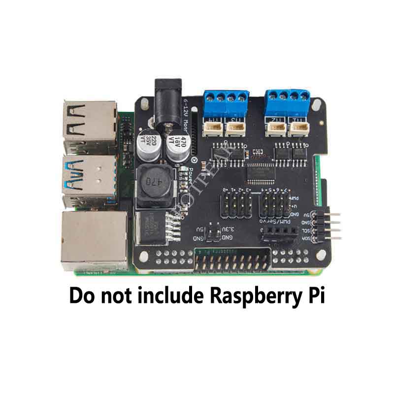
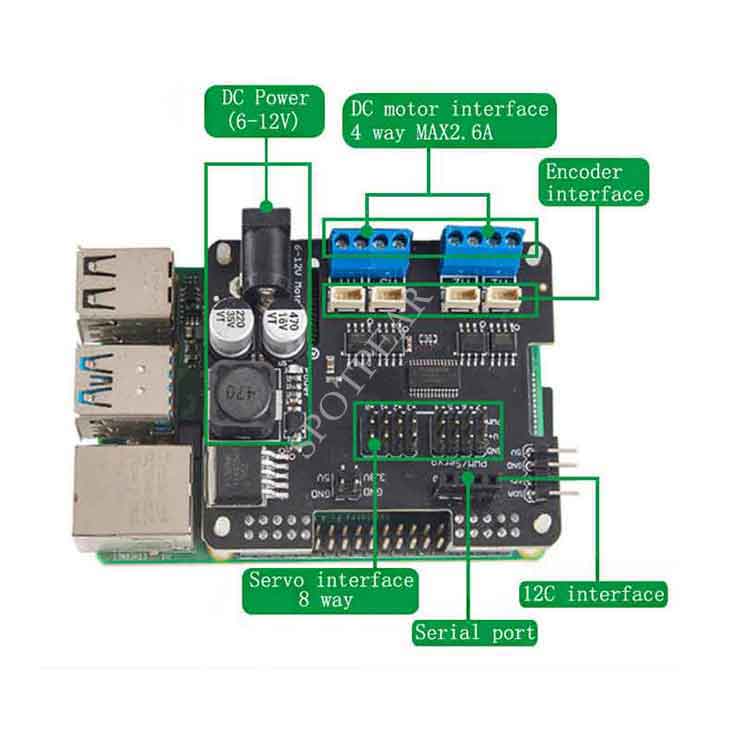
This is a perfect solution for making motion robots based on Raspberry Pi. This motor driver is powerful enough to drive 4 DC motors or 2 stepper motors, and additionally provides 4 channels of full-speed PWM control, which can control 4 channels of servos . With its own voltage regulator circuit, it directly provides a stable power supply for the Raspberry Pi.
 Raspberry Pi does not have enough PWM pins, using a dedicated PWM driver chip (PCA9685) based on I2C communication to control the speed and direction of the motor can save more Raspberry Pi resources. Only 2 GPIO pins (SDA & SCL) can be used to drive multiple motors, or multiple drivers can be stacked and used (cascadable) without interfering with the use of other I2C devices.
Features
- Each 2.5A (3.6A peak) output can run 4.5-13.5V DC motors;
- Can drive 4 DC motors or 2 stepper motors;
- Provide 8 additional PWM outputs, can control 8 servos
- I2C address can be customized, and multiple drivers can be stacked and cascaded;
- Integrates 5V regulator, allows providing power to Raspberry Pi
- Comes with development resources and manual (python)
二、Power description
- Because the driver needs to provide power for both the motor and the Raspberry Pi, it is recommended to use a power battery as the power source. The power supply voltage is 6-12V;
- The motor is directly powered by the power supply, so the input voltage of the motor is equal to the external power supply voltage;
- The driver has a built-in voltage regulator module, and outputs 5V2A to supply power to the Raspberry Pi and 4-channel PWM (servo);
- Different power supply modes can be selected by jumpers.
三、Software Installation
The driver is based on Raspberry Pi and runs in a linux environment, and the driver provides a Python library and related sample codes.
First of all, you need to make the I2C of the Raspberry Pi in Enable (for detailed configuration, please refer to the online information)
*Run the apt-get install python-smbus git installation smbus
Upload the code to the Raspberry Pi (eg "/home/pi") and try running the examples in the examples directory.
*If it prompts that the class library is not found, please configure the relevant library files, or directly copy the column library files to the current directory.
1、Control DC motor (DC motor)
a)Connect the motor
There are 4 sets of motor terminals on the driver board, which are M1, M2, M3, and M4. If you run the DCTest.py example, connect the motor to the M3 interface. Then run the following command:
b)DC motor Detailed example
Create a MotorHAT object and set the I2C address, the default address is 0x60 (for detailed address settings, refer to the following content)
Create a DC motor object
MotorHAT has a getMotor(num) method, num is 1~4.
Set the motor rotation speed
setSpeed(speed)
speed :0 (off)~ 255 (maximum!).
*The value of *speed is 0 to 255, and the speed is a relative value, which is related to the power supply voltage.
Set DC Motor direction
run(direction)
direction Defined as follows:
- Adafruit_MotorHAT.FORWARD – DC motor spins forward
- Adafruit_MotorHAT.BACKWARD – DC motor spins forward
- Adafruit_MotorHAT.RELEASE – DC motor is ‘off’, not spinning but will also not hold its place.
2、Use Stepper Motors (V5 version has not been updated yet, and does not support stepper motors)
The driver board can be connected to 2 stepper motors at the same time, both unipolar and bipolar are applicable.
a)Connect the motor Stepper Motors
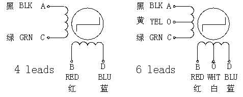 In the above picture, the left is the bipolar drive Bipolar stepper motors (4 lines), the right is the unipolar drive Unipolar Stepper Motor (6 lines)
- Unipolar Stepper Motor (6 wires): First, you need to know which wire is the center wire, then connect the central wire to the GND of the binding post (white and yellow in the right picture), and the remaining two sets of end wires (black and green) , red and blue) are connected to M1, M2 or M3, M4 respectively.
- Bipolar stepper motors (4 wires): Similar to unipolar drive, just leave GND blank.
StepperTest.py Example
Connect the stepper motor to M1, M2 and run it in the examples directory:
b)Detailed example
Create a MotorHAT object and set the I2C address, the default address is 0x60 (for detailed address settings, refer to the following content)
mh = Adafruit_MotorHAT(addr=0x60)
create Stepper motor object
myStepper = mh.getStepper(200, 1) # 200 steps/rev, motor port #1
getStepper(steps, portnum)
steps :How many steps per revolution (usually between 35 and 200)
portnum :1~2,Port #1 is M1 and M2, port #2 is M3 and M4
Set Speed, RPM(RPM)
myStepper.setSpeed(30) # 30 RPM
setSpeed() Set Speed, RPM(RPM)
step() – blocking steps
stepper1.step(100, Adafruit_MotorHAT.FORWARD, Adafruit_MotorHAT.SINGLE)
step(numberofsteps, direction, type)
numbersteps:Step count
direction:FORWARD or BACKWARD
type:SINGLE, DOUBLE, INTERLEAVE or MICROSTEP
*Please refer to the online information for the working characteristics of the stepper motor.
Using “Non-blocking” oneStep()
oneStep(direction, stepstyle) single step
3、Servo control
The servo control of the driver board is realized by the PWM special chip PCA9685, and the corresponding numbers are 0-7 respectively. Since ordinary servos on the market usually only support 50Hz signals, the frequency of pwm.setPWMFreq(50) is controlled at around 50.
四、Stacking cascade
When you feel that the motor interface is not enough, you can use multiple driver boards in cascade. We support stacking up to 4 drives.
Cascading multiple drives requires a unique I2C address for each drive, the default address is 0x60. The address range is from 0x60 to 0x63, a total of 4 addresses.
There are A0~A4 on the driver board in total
Board 0: Address = 0x60 Offset = binary 0000 (All are empty by default)
Board 1: Address = 0x61 Offset = binary 0001 (Only solder A0)
Board 2: Address = 0x62 Offset = binary 0010 (Solder only A1)
Board 3: Address = 0x63 Offset = binary 0011 (Solder A0 & A1 at the same time)
StackingTest.py is a code example of cascading overlay, the key part is creating 2 MotorHAT objects: